

Page 1
Grand Haven, Michigan 49417
616-842-7110 Phone 800-937-3253
616-842-0859 Fax 800-846-3253
Web: www.dakecorp.com
E-mail: customerservice@dakecorp.com
technicalsupport@dakecorp.com
724 Robbins Road
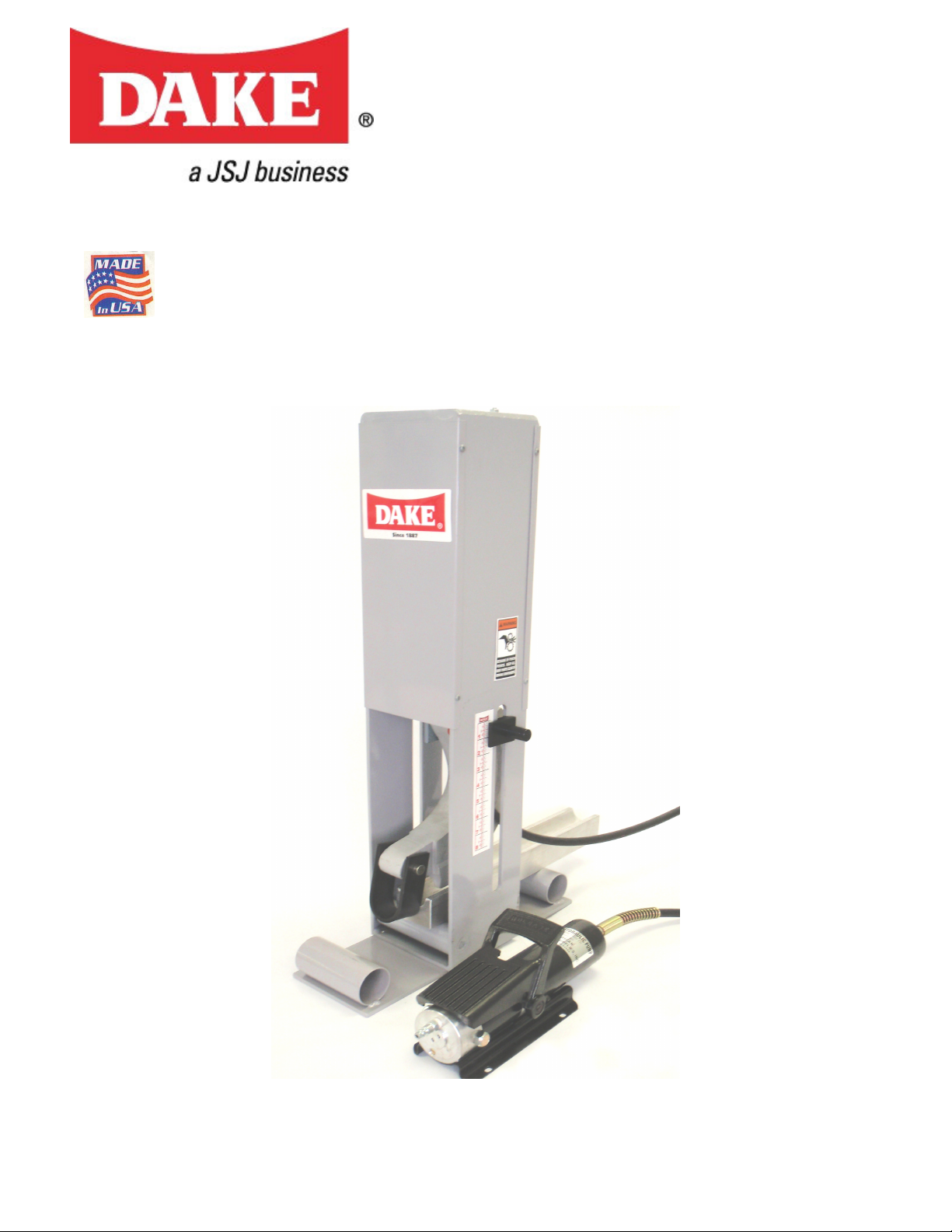
Dake Tube Bender Manual
Instructions and part list
Air operated
Dake Tube Bender manual 08212009 1
Page 2

Thank you for buying Dake!!!!
We hope you enjoy many years of using your New Dake Tube Bender. If after reading
this manual you still have any questions please give us a call, e-mail or stop by for a
factory tour.
www.dakecorp.com
724 Robbins Road
Grand Haven, MI 49417
Phone: 616-842-7110 800-937-3253
CAUTION!!!
Read and understand all warnings, cautions, attentions and instructions before operating
this equipment.
CAUTION general
When working always pay attention and be alert. Be careful. Be aware of possible
Hazards.
CAUTION regulations
Observe the law and regulations. Check local regulations to properly dispose of oil and/or items
that have been in oil to dispose of properly.
ATTENTION tools
Always check that your tools are in good condition and that the tools are suitable for the work to
make (ex. don’t use the pliers as hammers etc.)
ATTENTION tampering
It is severely forbidden to modify or to tamper with parts that can alter the
standard working conditions.
CAUTION operator
For no reason whatsoever must the operator have their hands in the area of the piece being bent
during the pressing operation.
CAUTION operator
Tube being bent must be at least as long as the follower bar. Shorter material lengths could result
in the follower bar flying out the rear of the work area.
CAUTION Air
Do not exceed 100 psi damage to the pump will occur.
According to new legislation, the employer will have to check that the
operator has understood these notices.
THIS MACHINE IS DESTINED ONLY FOR THE USE IT HAS BEEN DESIGNED
FOR, ANY OTHER USE IS TO BE CONSIDERED IMPROPER AND
THEREFORE THE MANUFACTURER CANNOT BE HELD LIABLE FOR ANY
DAMAGE CAUSED BY ANY IMPROPER USE OR USE NOT EXPRESSLY
MENTIONED IN THIS USER’S MANUAL.
Dake Tube Bender manual 08212009 2
Page 3
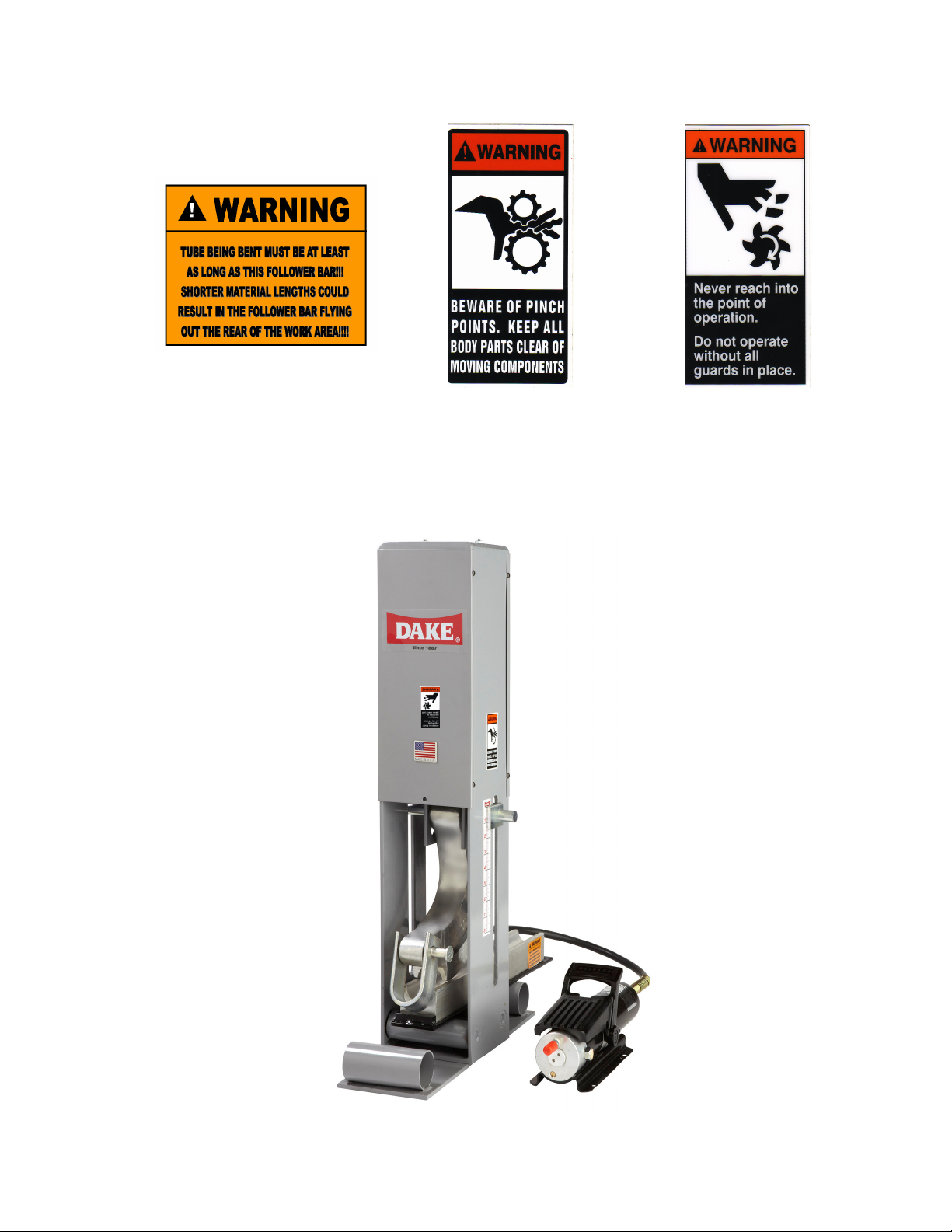
Before operating this equipment review and understand the safety labels
below that are on the tube bender.
Below is a picture of where these safety labels are on the machine.
Dake Tube Bender manual 08212009 3
Page 4

Removing your Dake Tube Bender from the packaging
When you receive your tube bender you will receive three boxes. One will have the following components
in the box.
Frame
Two nuts
Two bolts
Foot
Die pin
If you have ordered a power unit, in another box you will have either the manual or the air operated pump
Follower plate
Manual Pump Air operated pump
And in the third box you will have the follower bar, the die, the hook, and the hook pin.
There are different dies available they are listed below.
Only one set is included with the tube bender. Others are optional
items.
1.5”
1.666”
1.750”
There are different sizes of follower bars. When using the die be sure
the follower bar and die match to make sure you have the correct
bend. These come in sets of two, one die and one follower bar. They
are scribed with the size on the side of the die and the follower bar.
Dake Tube Bender manual 08212009 4
Page 5

Assembly of your Dake Tube Bender
should be against
Lay the tube bender on it’s side (as pictured below) take the foot and line up the holes to the bottom of the
bender frame. Make sure the tubes on the foot face up towards the frame (it should look like the picture
below when the foot is installed). Install the bolt and nut so that the nut is up in the frame. Snug the bolts
down so that there tight. Do not over tighten the bolts!!!
Pick up the bender and set it on it’s foot (as pictured below).
There is a wire holding the ram plate in place for shipping.
you will need wire cutters or pliers to remove it. It does not
stick out like shown in the picture. You will need to look
under the cover to see it.
This shoulder
the frame when
completely
installed.
Take your die and die pin and install it
as shown above. Be sure the pin is in all
the way.
Dake Tube Bender manual 08212009 5
Page 6

There is a set screw on the end
of the follower bar to holde the
die and follwer bar together. Be
sure this set screw is tight.
When installing the hydraulic line make sure the hydraulic line travels through the welded ring inside the
frame. When the hydraulic line is installed reinstall the cover using the allen button head screws to hold it
in place.
Take your follower plate and set your follower on the center of it and
lock it in place with the set screw on the follower. Take your follower
plate assembly and set it on the rollers in the frame of your tube bender.
Next, you will need to
access the hydraulic line.
Remove the four allen
head screws on the right
side panel. You should be
facing the side with no
measurement sticker.
Remove this side
to access the
hydraulic line.
Welded ring
Be sure the hydraulic line is tight.
Hook pin
Hook
Using the U-shaped hook and hook pin,
install as shown above.
Dake Tube Bender manual 08212009 6
Page 7

Now just hook up your airline (DO NOT EXCEDE 100 PSI) and put in a piece of material and your ready
to start bending.
Remember!!!
Never use a piece of material shorter than the follower bar!!!
Make sure the pins are fully engaged!!!
Never stand in front of or behind the work area or work piece!!!
Do not use more than 100 psi !!!
Never remove the hydraulic line with pressure in the line!!!
Maintenance
Oil the rollers mounted on the bottom of the frame every once in a while.
If for any reason you need to add oil you can on the bottom of the air pump.
WARNING!!!
NEVER REFILL OIL WITH AIR PRESSURE OR HYDRAULIC PRESSURE IN THE
LINES.
Troubleshooting
If the piston sticks down make sure the hydraulic line is installed correctly, it may not be
tightened down correctly.
If for any reason you have questions or concerns please call Dake at 1-800-937-3253 or
at www.dakecorp.com
Dake Tube Bender manual 08212009 7
 Loading...