

Page 1
INSTRUCTIONS AND PARTS LIST FOR
Models 5-025, 5-050, 5-075, and 5-150
Elec-Draulic I Presses
WARNING LABELS
To the left is the safety Alert symbol. When you see these safety alert symbols on your press,
be alert to the potential for personal injury.
Follow recommended precautions and safe operating practices.
SETTING UP THE PRESS FOR OPERATION
For shipping convenience some of the parts are not assembled. Assemble these parts in the following order:
1. Bolt the base angles to uprights using four bolts and nuts, which are provided. Make sure base
angles are against stops on uprights.
NOTE: The press should set on a level floor with the base angles touching the floor at all
points. Use shims where necessary.
2. Motor starter box is mounted on left upright. Have electrician connect power to motor starter. Pump
can rotate in either direction.
3. Oil Requirements: Fill reservoir thru street elbow at back of press with Mobil DTE oil No. 24 or
equivalent. NOTE: Oil level may be checked (with ram up) by removing the 1/8” NPT pipe plug
on the right side of reservoir near the front. Replace plug before operating the press.
Model 5-025 uses 6 quarts
Model 5-050 uses 8 quarts
Model 5-075 uses 10 quarts
Model 5-150 uses 20 quarts
4. Prime pump by removing the plug in the top of the pump opposite the intake line and allow the oil
levels in the reservoir and pump to equalize. Fill pump with additional oil (if required), replace plug
making sure seal is tight, and start motor.
5. Attach nose piece to ram by inserting shank into ram and tightening the set screw.
CAUTION! Place the hoist crank on the lift drum shaft. Turn the hoist crank to relieve
the pressure on the table pins. Keeping tension on the hoist crank, remove the table pins one
at a time. After removing the tables pins, turn the crank running the table channels from top to
bottom. Check to make sure the cable is tracking correctly. The cable should be on each of
the two upper pulleys and should track back and forth on the cable drum. Always place table
pins under the table channels before releasing the hoist crank when positioning the table
channels for cable tracking, servicing, or set-up for desired work opening. If a tracking
problem exists, contact the Dake factory for instructions. Be sure all table pins are fully
inserted in place before applying pressure. Always remove or release pressure on the cable
before pressure is applied.
OPERATIONS
WARNING: DO NOT OVERSTROKE THE RAM. Overstroking will cause premature seal failure.
Models 5-025, 5-050, & 5-075 have a 10-inch stroke. Model 5-150 has a 16-inch stroke.
The press has been completely tested at the factory and after setting up according to instructions above, the
press is ready for operation. However, it is necessary for the operator to acquaint themselves with the
controls.
1. Three screws (item 100) are used to lock the workhead in the desired position along head
channels.
2. The handcrank (item 19) is provided to raise or lower the table channels to the proper work height.
When desired height is obtained insert the table pins. Models 5-025 and 5-050 use 2 pins on each
side (4 total) and Models 5-075 and 5-150 use 3 pins on each side (6 total).
Model 5-025, 5-050, 5-075 & 5-150
1
Page 2
3. The handle on the left side of the workhead (item 67) opens and closes the ball valve, which
4. The two table plates (items 6) and two V-blocks (item 7) are used for supporting the work in
5. The control handle (items 86 & 91) on the right side of the panel regulates the speed of ram travel.
6. The relief valve (item 79) has been set at factory to open at maximum tonnage of press. The valve
MAINTENANCE
CAUTION: When disconnecting any parts of this machine be extremely careful that all parts are
clean to prevent entrance of dirt in the hydraulic system.
1. If press looses pressure:
CAUTION: Be sure ALL table pins are in place an in as far as they can go before
pressure is applied. Be sure to slack off on the cable before pressure is applied.
releases pressure on the ram. This valve should be kept firmly closed and open only when it is
desired to return the ram to its up position.
process.
The handle will return to the off position when released. It is not necessary to stop motor after each
operation.
can be adjusted by removing hex nut located on top of the valve block at the right front of reservoir
and turning the adjusting screw to the left for a lower setting.
WARNING: Never exceed rated tonnage of press
a. Check all tubing joints for leaks and tighten the tube nuts.
b. Leakage past release valve (Item 67). Drain the reservoir, and remove packing nut (Item 75),
valve rod (Item No 64), and ball valve (Item No 63). Clean out valve seat and reseat ball valve
using brass rod as a drift striking sharply with a hammer. Reassemble valve rod, packing and
packing nut. Refill reservoir with appropriate oil amount.
c. Leakage past eductor inlet check ball (Item No. 60). Drain reservoir, remove large pipe plug
(Item No. 62), valve seat (Item No. 61), and check ball (Item No. 60). Clean and inspect seat.
Reseat ball on seat or replace seat with a new one if necessary. Reassemble with ball above
the seat tightening plugs securely.
d. Worn cup leather (Serial No < 192522) or T-ring seal (Serial No > 192523). If none of the
previous conditions seem to have been the cause of the trouble, the cup leather or T-ring seal
may be worn out or damaged. To inspect this it is necessary to drain the oil and remove the
workhead from the press frame. Remove tube assembly (Item No. 123). Set 2 4x4 blocks on
the table then raise table channels with the block up to the bottom of the reservoir applying
pressure to the reservoir. Remove roller brackets from the reservoir and lower workhead using
the table.
hold the piston down under spring pressure. Next remove nuts from cylinder flange and lift
cylinder off piston. The piston leather or T-ring seal can now be inspected and replaced if
necessary. Press may be reassembled in reverse order being careful not to damage the lip of
the leather cup or T-ring seal as it enters the cylinder.
2. If press will not develop rated tonnage.
a. Dirt under valve balls. Refer to MAINTENANCE 1 – c above.
b. Worn cup leather. Refer to MAINTENANCE 1 – d above.
c. Relief valve not set properly. This valve is located on the top side near the right end of the
Model 5-025, 5-050, 5-075 & 5-150
WARNING: Be sure that stroke indicator rod support (item 52) is installed in the side
of the piston. If not, Insert ½”-13 stud or capscrew in tapped hole in piston. This will
control block at the front of the reservoir. The valve is set at the factory to bypass oil from the
pump back to the reservoir when the press reaches its rated capacity. The load on the spring
(Item 75), which governs the pressure at which the valve will bypass oil, is adjusted by turning
the screw (Item 79) in to increase pressure or out to decrease pressure. Replace seal (Item
74) and cap nut (Item 78). NOTE: We advise that the relief valve not be tampered with
after it is set at the capacity of the press.
2
Page 3

3. If nothing happens when press is operated.
a. If motor does not run, the electrical circuit should be investigated.
b. Release valve open. Be sure to have release valve firmly closed when using press.
c. If the ram will come down only a fraction of its rated stroke, check the oil level in the reservoir
with the ram at the top of its stroke. It should be visible in the sight window at the side of the
reservoir.
d. Eductor nozzle plugged. If motor labors and ram does not move when pump control know is
turned, the orifice in the eductor nozzle (item 73) may be plugged. Drain reservoir, remove tube
assembly (Item 123), eductor bushing (item 70), eductor body (item 72), and eductor nozzle
(Item 73). Clean out orifice with a 1/32” drill. Replace parts being sure not to install item 72
backwards. See parts drawing. Check O-ring and back-up washer (items 71A &71B) to be sure
it has not been damaged.
4. If press is operating slow.
a. Improper oil. It is essential that the recommended oil (Mobil DTE 24 or equivalent) be used.
Heavier oils cause a marked reduction in the ram speed. NOTE: DO NOT USE HYDRAULIC
JACK OIL!
b. Release valve not closed properly. Release valve must be firmly closed when using the press.
c. The seal on the piston rod for the 50-101 pump is worn. A worn seal will pull air into the pump
causing the pump to slowly loose its prime. To test, place grease around the control rod where
it goes in and out of the seal (Item 129). Then replace seal part number 26573.
d. The piston rod for the 50-101 pump is bent or rusted. Contact factory for rebuilding your pump.
CAUTION: Adjustments to pump are not necessary and the pump should not be tampered with
because expensive repairs may result.
WARNING! High pressure fluid is present in operational hydraulic systems. Fluids under high
pressure are dangerous and can cause serious injury or death. Do not make modifications, repairs or
adjustments to any hydraulic system unless you are competent or working under competent
supervision. If in doubt, consult a qualified technician or engineer.
Model 5-025, 5-050, 5-075 & 5-150
3
Page 4
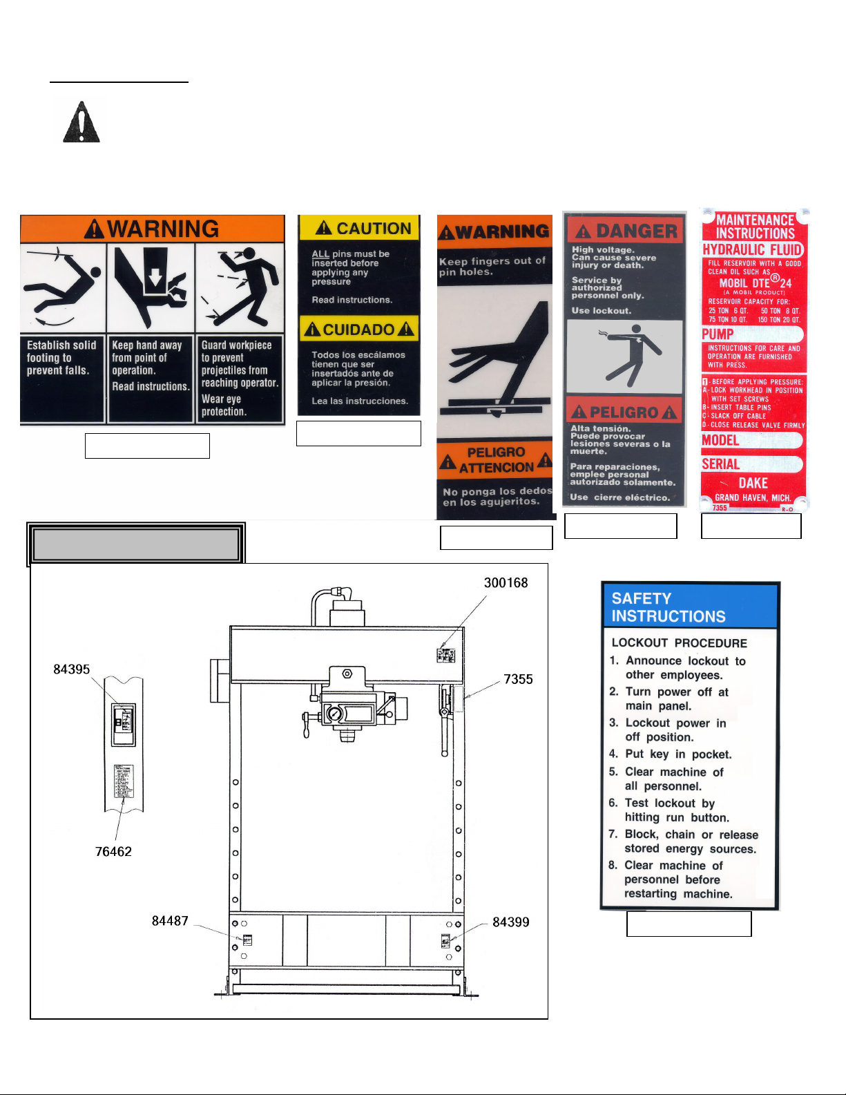
Label 300168
Label 84487
Label 84395
Label 76462
Label 7355
WARNING LABELS
To the left is the safety Alert symbol. When you see these safety alert symbols on your press,
be alert to the potential for personal injury.
Follow recommended precautions and safe operating practices.
Carefully read all safety messages in these instructions and on your press safety signs.
Keep safety labels in good condition. Replace missing or damaged safety labels. This machine is intended
to be operated by one person. This person should be conscious of the press ram movement not only for
himself but also for persons in the immediate area of the machine.
Label Placement View
Model 5-025, 5-050, 5-075 & 5-150
4
Page 5
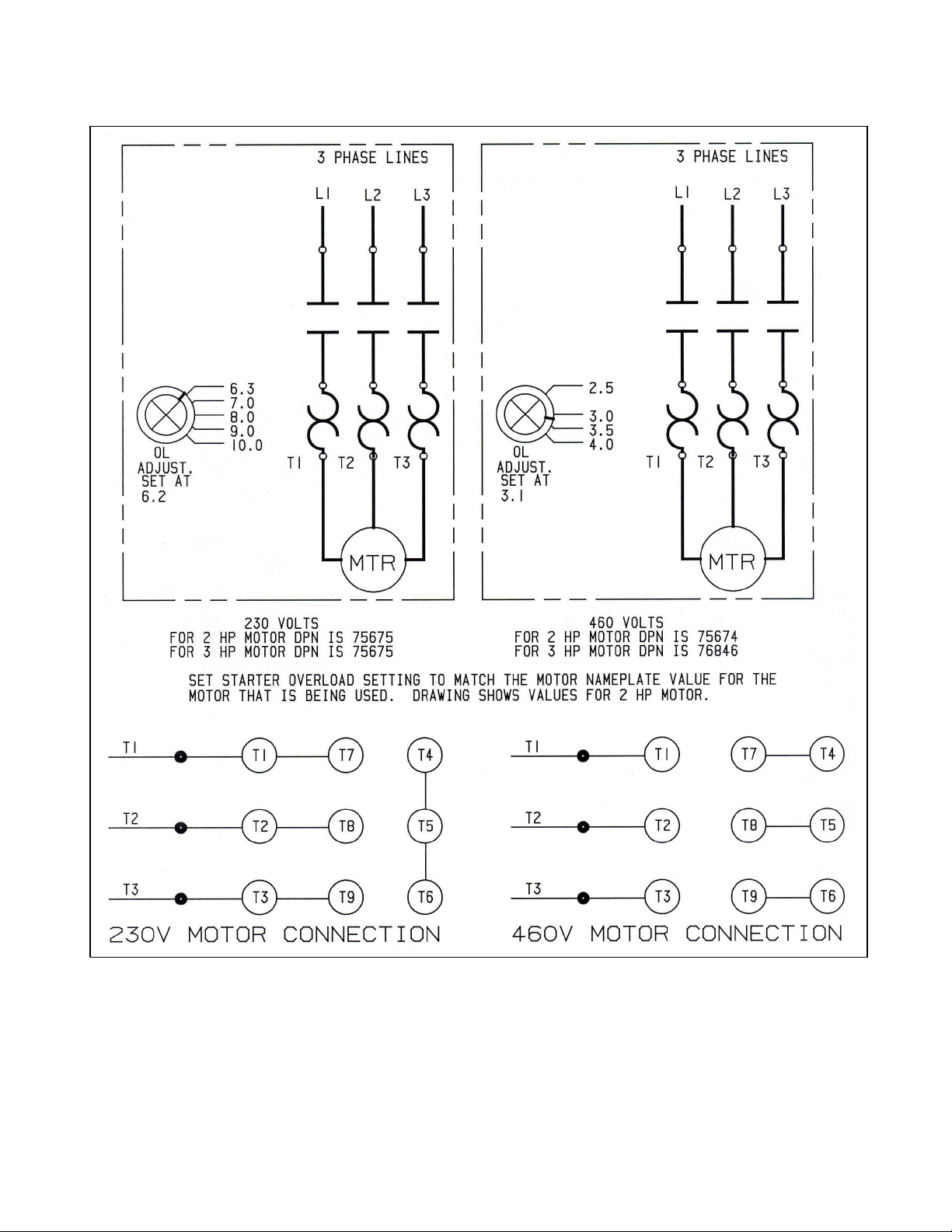
Model 5-025, 5-050, 5-075 & 5-150
Electrical Diagram
5
Page 6

Model 5-025, 5-050, 5-075 & 5-150
6
Page 7

Model 5-025, 5-050, 5-075 & 5-150
7
Page 8

Eductor Block Exploded View
Model 5-025, 5-050, 5-075 & 5-150
8
Page 9

Figure 1
Item Part Name
1 Pulley 602 602 727 1563 2
2 Frame 701151 701151 701152 701030 1
3 Hex head cap screw 43342 43342 43361 43720 2
4 Name plate 81002 81002 81002 81003 1
6-32 x ½” Self tapping screw (current
5
models glued)
6 Table plate 545 545 702 1534 2
7 V-block 336 336 336 1576 2
8 Table spacer assembly (8, 10 & 11) 716691 716692 716788 1533 4
9 Table channel 4100 4100 2243 4207 2
10 Lockwasher 43647 43648 43648 43649 4
11 Hex nut 43916 43917 43917 43919 4
12 Table pins 2256 2256 - - 4
Table pins - - 2256 1555 6
13 Base angle 566 566 566 1551 2
14 Hex cap screw 43349 43349 43349 43365 4
15 Lockwasher 43647 43647 43647 43648 4
16 Hex ½-13 Heavy 43916 43916 43916 43917 4
17 Cable 580 580 726 1562 1
18 Cable clamp 991 991 991 583 4
19 Hand crank assembly 701653 701653 701653 701653 1
20 Worm shaft 7530 7530 7530 742 1
21A Retaining ring 43992 43992 43992 43982 2
21B Retaining ring 27437 27437 27437 43983 2
22 Worm key 47364 47364 47364 746 1
23 Worm 385 385 385 744 1
24 Hoist frame 725 725 725 739 1
25 Hex cap screw 43335 43335 43335 43353 3
26 Hex nut 43912 43912 43912 43916 4
27 Drum shaft 724 724 724 741 1
28 Drum key 737 737 737 745 1
29 Worm gear 736 736 736 743 1
30 Cable drum 723 723 723 740 1
Complete Table Hoist Assembly
(Items 20, 21A, 21B, 22, 23, 24, 27, 28, 29,30)
Model
5-025
43876 43876 43876 43876 4
701677-S 701677-S 701677-S 700111-S 1
Model
5-050
Model
5-075
Model
5-150
Qty
Figure 2
31 ½” hex nuts 43916 43916 43916 43916 4-6
32 ¼ x 1/8 NPT elbow 19576 19576 19576 19576 1
33 Cylinder Gasket 9777 9777 9777 9778 1
½”-13 x 1-½“ SHCS Serial No < 192522
34
Piston Bumper Serial No < 192522
35
Hex head cap screw Serial No < 192522
36
Lockwasher Serial No < 192522
37
Supporting ring Serial No < 192522
38
Leather Cup Serial No < 192522
39
T-ring seal Serial No > 192523
40 Ram spring (Small) 5722 4107 2231 4196 1
41 Spring spacer 5725 4108 2233 4201 1
42 Ram spring (Large) 5721 4106 2232 4195 1
Piston bushing Serial No < 192522
43
Wear Ring Serial No > 192523
44 Oil seal 6019 6020 6021 1477 1
45 5/16” set screw 43575 43575 43575 43575 1
46 Nose piece assembly with shank 701706 701707 701708 701709 1
47 “V” nose piece assembly with shank 701710 701711 701712 701713 1
Model 5-025, 5-050, 5-075 & 5-150
- 43471 43471 - 8
- 2221 2221 - 1
43305 43330 43332 43332 8
43643 43645 43645 43645 8
967 4110 2222 1536 1
969 557 706 1538 1
17976 17878 17942 37052 1
5731 4111 2229 1158 1
76805 76806 76807 37045 1
9
Page 10

Item Part Name
Model
5-025
Model
5-050
Model
5-075
Model
5-150
Qty
48 Stroke indicator rod 2260 2260 2260 4264 1
49 ½”-13 hex jam nut 43940 43940 43940 43940 1
50 Special nut 2259 2259 2259 2259 1
51 ¼”-20 x ¼” Set Screw 43558 43558 43558 43558 1
52 Support stud 2258 2258 2258 4266 1
No. 2 x 3/16” Drive Screw (new style
53
glued on)
43573 43573 43573 43573 3
54 Scale 2261 2261 2261 4265 1
55 Reservoir assembly 715270 705601 705923 715273 1
56 Piston assembly
Piston assembly
Serial No. < 192522
Serial No. > 192523
701401 701402 701403 701404 1
716225 716226 716227 716228 1
57 Check valve seat 1300 1300 1300 1300 1
58 ½” N.P.T.F. socket head pipe plug 596 596 596 596 1
59
3/8
” N.P.T.F. socket head pipe plug 588 588 588 588 2
60 ½” ball valve 586 586 586 586 2
61 Intake valve seat 1301 1301 1301 1301 1
61A Valve guide 10752 10752 10752 10752 1
61B Spring pin 44333 44333 44333 44333 1
62 1” N.P.T.F. socket head pipe plug 44282 44282 44282 44282 1
63 Ball valve ¾” dia. 1936 1936 1936 1936 1
64 Release valve rod 2257 2257 2257 2257 1
65 Valve rod packing 1937 1937 1937 1937 8
66 Packing nut 1931 1931 1931 1931 1
67 Valve handle 2230A 2230A 2230A 2230A 1
68 Handle washer 348 348 348 348 1
69
3/8”-16 x
½” hex cap screw 43324 43324 43324 43324 1
70 Eductor bushing 1288 1288 1288 1288 1
71a O-ring 916 916 916 916 1
71b Back-up washer 11223 11223 11223 11223 1
72 Eductor body 2241 2241 2241 2241 1
73 Eductor nozzle 1287 1287 1287 1287 1
74 O-ring 3965 3965 3965 3965 1
75 Relief valve spring 893 893 893 893 1
76 Ball valve ¼” dia. 918 918 918 918 1
77 Relief valve seat 891 891 891 891 1
78 Valve cap nut 2236 2236 2236 2236 1
79 Relief valve adjusting screw 2237 2237 2237 2237 1
80 Ball retainer 892 892 892 892 1
81 Cylinder 5726 4101 2213 4197 1
82 Check valve spring 579 579 579 579 1
83 Gauge 71270 71271 71272 71273 1
84A Control panel - Old Style 3-1/2” hole 27618 27618 27618 27618 1
Control panel - New Style 4” hole 80744 80744 80744 80744 1
84B Label for panel 27620 27620 27620 27620 1
85 Spring pins
1/8”
dia.
x 9/16”
28524 28524 28524 28524 3
86 Control handle ball 27879 27879 27879 27879 1
87 No.
88 No.
10-24 x 3”
10-24 x 3/8
Flat head slotted screw 300248 300248 300248 300248 4
” soc. head cap screw. 43396 43396 43396 43396 2
89 Control handle mounting bracket 27622 27622 27622 27622 1
90 Control rod 27621 27621 27621 27669 1
91 Control handle 27433 27433 27433 27433 1
Model 5-025, 5-050, 5-075 & 5-150
10
Page 11

Item Part Name
Model
5-025
Model
5-050
Model
5-075
Model
5-150
Qty
92 Neoprene washer 2248 2248 2248 2248 4
93 ¾” pipe nipple x 8” 44205 44205 44205 44205 1
94 Vent tube 6038 6038 6038 6038 1
95 Retaining plate 7359 6513 6514 6474 1
96 5/8” flat washers 49927 49927 49927 49927 7
97 5/8”-11 hex nut 43917 43917 43917 43917 7
98 5/8” lockwasher 43648 43648 43648 43648 7
99 Rear roller bracket 9472 9472 9472 4204 1
100 ¾”-10 x 3” Soc set screw 43616 43616 43616 43616 3
101 3/8”-16 x 1” hex cap screw 43328 43328 43328 43328 4
102 Roller screw 1297A 1297A 1297A 1297A 3
103 Flanged roller 2244 2244 2244 2244 3
104 Bearing 6023 6023 6023 6023 3
105 Front roller bracket 9473 9473 9473 4205 1
106 Motor – 2 HP, 220/440 volt 3-phase 29744 29744 29744 29744 1
106A Bolts, motor mounting (5/16-18 x ½”) 43313 43313 43313 43313 4
107A Coupling (with Spider) 28498 28498 28498 28498 1
107B Spider only 301337 301337 301337 301337 1
108 Gasket 6516 6517 6518 6519 1
109 3/8”-16x1” hex cap screw 43328 43328 43328 43328 8
110 3/8” lockwasher 43645 43645 43645 43645 8
111 Pump and motor base 25915 25915 25915 27668 1
112 Pump 950101 950101 950101 950101 1
113 ½” lockwasher 43647 43647 43647 43647 4
114 ½”-12x1-½” hex head cap screw 43469 43469 43469 43469 4
115 1/8” Allen pipe plug 589 589 589 589 1
116 Pump support 25916 25916 25916 25916 1
116A Bolts, pump support (5/16-18 x ¾”) 43314 43314 43314 43314 4
117 Tube fitting 1251 1251 1251 1251 1
118 Tube assembly 705921 705921 705921 705921 1
119 Tube elbow 1252 1252 1252 1252 2
120 Tube assembly 701160 701160 701160 701161 1
121 ¾”-90 degree pipe elbow 44110 44110 44110 44110 1
122 Tube elbow 1944 1944 1944 1944 2
123 Tube assembly 701162 701163 701164 701165 1
124 Tube fitting 597 597 597 597 1
125 Tube 6038 6038 6038 6038 1
126 ¼” Allen pipe plug 1567 1567 1567 1567 1
127 #10-24x ½” Rd Head Machine Screw 43881 43881 43881 43881 6
128 Tube elbow 17999 17999 17999 17999 1
129 3/8” Wiper seal – on 50-101 pump 26573 26573 26573 26573 1
Cylinder Repair Kit
65, 71A, 71B, 74, 76 & 108)
Complete Workhead assembly
Specify Voltage
(Includes items 33, 39, 44, 60, 63,
(Includes all items in figure 2)
706553 706554 706555 706556
905026 905051 905076 905151
Model 5-025, 5-050, 5-075 & 5-150
11
724 Robbins Road
Grand Haven, MI 49417
Phone: 616-842-7110 800-937-3253
Fax: 616-842-0859 800-846-3253
Web: www.dakecorp.com
E-mail: customerservice@dakecorp.com
technicalservice@dakecorp.com
Page 12

INSTRUCTIONS AND PARTS LIST FOR
I. DESCRIPTION
This unit is a five-piston axial type piston pump designed for heavy-duty industrial application up to
6000 psi continuous and 8000 psi intermittent. The pump should be coupled directly to the driving
source and can be rotated in either direction.
II. TYPICAL VARIABLE VOLUME CONTROLS
A. Stem control – with control stem out (spring return), output delivery is zero gpm – pushing in on
control stem increases pump delivery from zero to maximum gpm.
B. Knob control – With control knob adjusted out (counter-clockwise rotation), output delivery is
zero gpm – turning control knob clockwise increases pump delivery from zero to maximum gpm.
C. Pressure compensated – Circuit operating pressure is controlled by setting of compensator
valve mounted on pump. Turning adjusting knob clockwise increases circuit pressure, counterclockwise decreases circuit pressure. Output delivery of pump at zero circuit pressure is
maximum gpm – when circuit pressure reaches the setting of compensator valve, pump output
automatically decreases to supply the exact flow rate required by the system.
Models 50-101
¾ GPM Hydraulic Pump
Variable volume – stem control
III. INSTALLATION
A. Rotation – Pump shaft rotation can be in either direction.
B. Shaft alignment and pump mounting – The alignment of the pump and motor is critical, having a
direct relation to pump bearing and shaft seal life as well as coupling life. A flexible coupling
should always be used.
C. Fluid connections – Pressure and intake line piping should correspond to port sizes to keep fluid
velocities in an n acceptable range. Do no bush down to smaller sizes.
D. Safety valves – The high-pressure line must have a relief valve close to the high-pressure outlet
to prevent damage to pump. In a circuit using the pressure compensated pump, the relief valve
should be set several hundred psi above compensator pressure to minimize transient pressures
due to compensator overtravel.
E. Filtration – Cleanliness of fluid and components is of extreme importance in high-pressure
hydraulic circuits. A suction strainer of 140 microns or less and twice pump capacity should be
used in the pump inlet line.
IV. MAINTENANCE
A. Minor repairs – Minor repairs are considered those that do not involve total disassembly of
pump. External leaks around the pump, for example, can usually be eliminated by tightening
screws and/or fittings around the leakage area. Replacement of leaking shaft or o-ring seals is
a minor repair that can be done in the field. The Dake service manual should be consulted for
the necessary part numbers.
B. Major repairs – Major field repairs can be accomplished in an emergency. However, it is
recommended that the Dake factory be contacted for necessary parts and assistance. Dake
pumps are built to give long-term dependable service. If they should eventually require
overhaul, factory rebuilding is recommended when possible since disassembly and assembly
can damage many parts. This minimizes replacements, with net savings to the user.
Model 5-025, 5-050, 5-075 & 5-150
12
Page 13

Trained Dake personnel with complete rebuilding and testing facilities permit rapid overhaul and
testing, resulting in minimum downtime for the customer, as well as the added advantage of
complete factory testing after repair.
TROUBLE SHOOTING CHART
TROUBLE POSSIBLE CAUSE REMEDY
Inadequate or no
flow from pump.
Pump will not
build pressure.
Pump is running
hot.
Noisy pump or
system.
Pump will not
prime or looses
prime.
1. Inlet line above fluid level.
2. Air in suction.
3. Pump not primed.
4. Broken drive shaft or coupling. Loose
coupling.
5. Oil viscosity too high.
6. Dirty or clogged oil suction filter.
7. Broken piston return spring item NN
or check valve spring item DD.
1. Loose check valve seat retainer items
BB.
2. System relief valve stuck open.
1. System relief valve constantly spilling.
2. Duty cycle excessive at high pressure.
1. Air in system.
2. Pump cavitating.
3. Coupling misalignment.
4. Broken piston return spring item NN.
5. Loose piston shoe item L.
1. Loose cylinder locking screws items
W.
2. Worn or damaged shaft seals items C
or AC.
3. Faulty o-ring items V, MM, TT or AB.
4. Air in suction.
1. Check fluid level and provide
adequate fluid to fill entire system.
2. Check for loose inlet line
connections.
3. Fill pump cast with Mobil DTE 24
oil or equivalent and run until
pump picks up prime.
4. Replace broken parts and tighten
setscrews in coupling.
5. Use proper viscosity fluid for
operating temperature conditions.
6. Clean filter and check at least
once a month.
7. Replace broken parts and
reassemble.
1. Retighten loose parts. Use
locktight when retightening.
2. Check valve for contamination.
1. Check relief valve setting and work
cycle.
2. Install oil cooler on fluid reservoir.
1. Bleed all circuit trapped areas.
2. Check for restriction in pump inlet
or loose fittings in inlet line.
3. Realign couplings.
4. Replace broken parts and
reassemble.
5. Replace with new parts items L
and M.
1. Tighten screws.
2. Replace with new parts.
3. Replace with new parts.
4. Check for loose fittings and
tighten.
724 Robbins Road
Grand Haven, MI 49417
Phone: 616-842-7110 800-937-3253
Fax: 616-842-0859 800-846-3253
Web: www.dakecorp.com
E-mail: customerservice@dakecorp.com
technicalservice@dakecorp.com
Model 5-025, 5-050, 5-075 & 5-150
13
Page 14

Model 5-025, 5-050, 5-075 & 5-150
14
Page 15

ITEM QTY DESCRIPTION MAT’L
724 Robbins Road
A 1 Pump Shaft HRS 25110
B 1 Key CRS 300449
C 2 Oil Seal STD 26184
D 1 Retaining Ring - Truarc STD 27468
E 2 McGill Roller Brg. MR-14 STD 26186
F 1 Rollway Thrust Brg. T618 STD 26185
G 1 Wobble Plate HRS 25200
H 1 Woodruff 608 Key STD 300449
J 1 Pump Body C.I. 25109
K 1 Rollway Thrust Brg. T619 STD 26187
L 5 Piston Shoe Bronze SAE64
M 5 National Retaining Ring XSO-117 26188
N 5 Spring Retainer CRS 25116A
P 5 Piston HRS 25114
R 5 National Retaining Ring XSO-122 27751
S 5 Piston Rotating Gear CRS C1141 25115
T 12 5/16-18 x ¾ Soc. Hd. Cap Scr. STD 43433
U 1 Control Gear CRS C1141 25120
V 2 O-ring 5-3/8 ID x 5-5/8 OD STD 26183
W 5 Cylinder Locking Scr. 25121
X 5 Metalic Seal Copper 26629
Y 5 Cylinder HRS 25113
Z 5 O-ring 9/16 ID 11/16 OD STD 26564
AA 5 Valve Seat CRS 25122A
BB 5 Seat Retainer CRS 25123A
CC 5 Check Valve Ball STD 1222
DD 5 Check Valve Spring Spring Steel 25126
EE 1 Thrust Washer Fibre 27439
FF 2 Truarc Retaining Ring STD 27437
GG 5 Pump End Cap CRS 25124
HH 5 O-ring ¾ ID x 15/16 OD STD 3966
JJ 1 Pump Head HRS 25111
KK 6 5/16-18 x 5/8 Soc. Hd. Cap Scr. STD 43432
LL 1 Flange Casting CI 27424
MM 1 O-ring 3-3/4 ID x 3-15/16 OD STD 27438
NN 5 Piston Spring Spring Steel 25119
PP 5 1/8 Spiral Spring Pin x 7/8 STD 28688
RR 1 Center Body Casting CI 26181
SS 1 Control End Cap CRS 27440
TT 1 O-ring 7/8 ID x 1-1/8 OD STD 3965
UU 1 Spring Music Wire 27441
VV 1 Control Rod End Spacer CRS 25132
WW 1 10-24 x 3/8 Soc. Hd. Cap Scr. STD 43397
XX 1 Control Pin CRS 25131
YY 4 ¼-20 x ½ Soc. Hd. Cap Scr. STD 43412
ZZ 1 End Cap HRS 25129
AB 1 O-ring ¾ ID x 15/16 OD STD 3966
AC 1 Oil Seal STD 26573
AD 1 Control Rod CRS 25912
1 Label 26190
2 Drive Screws for Label 43573
5 Pipe Plug – 1/16 NPTF 44276
PUMP REPAIR KIT
– Includes items B, C, Z, V, HH, MM, TT, AC & AD
Model 5-025, 5-050, 5-075 & 5-150
15
PART
NUMBERS
50-101
25117A
712740
Grand Haven, MI 49417
Phone 616-842-7110
800-937-3253
Fax 616-842-0859
800-846-3253
When ordering parts
Specify:
1. Quantity
2. Description
3. Part Number
4. Model Number
 Loading...