

Page 1
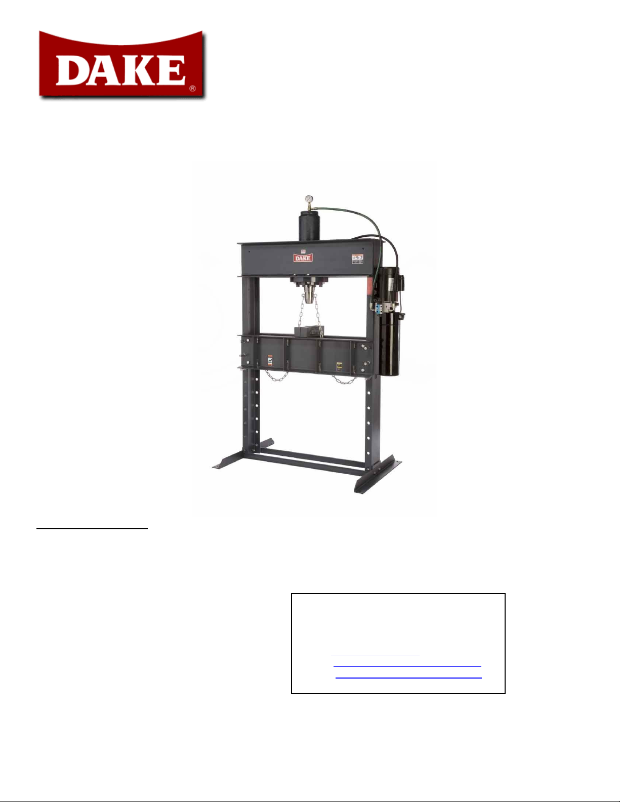
FORCE 50 DA HYDRAULIC PRESS
INSTRUCTIONS AND PARTS LIST
Ordering information
Please order all parts by part number and name; also mention model number as shown on plate attached to the
frame of the press. Prices do not include freight and handling charges.
724 Robbins Road
Grand Haven, MI 49417
Phone: 616-842-7110 800-937-3253
Fax: 616-842-0859 800-846-3253
Web: www.dakecorp.com
E-mail: customerservice@dakecorp.com
3/29/2010 1
technicalservice@dakecorp.com
Page 2

Thank you for buying Dake !!!!
We hope you enjoy many years of using your new Dake hydraulic press. We hope you find these instructions
helpful, if you have any questions please give us a call, or just stop by for a factory tour.
724 Robbins Road
Grand Haven, MI 49417
Phone: 616-842-7110 800-937-3253
3/29/2010 2
Page 3
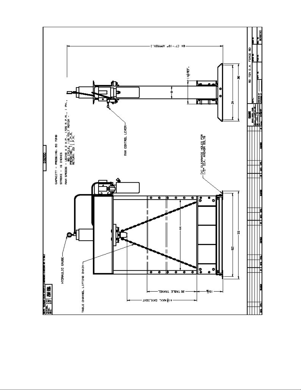
Dimensional drawing of 50 ton press
3/29/2010 3
Page 4
MACHINE SPECIFICATIONS
Tons 50
Stroke 16 inches
Pressing speed 11 Inches per minute
Return speed 20 Inches per minute
Daylight 41 3/4
Table travel 30 Inches
Between channels 44 Inches
Motor
1725 R.P.M
Weight 1200 lbs.
Approx. height 7’ 10” / 94”
1. Remote relief valve part number 301949. This will make the tonnage adjustable from 290 – 3537
p.s.i.
2. Check valve makes the press hold pressure part number 302071
3. Side mounted arbor part number 02007. This press will mount on the left side of the 50 DA press.
2 horse power / 60
cycle / 115/220 Volt
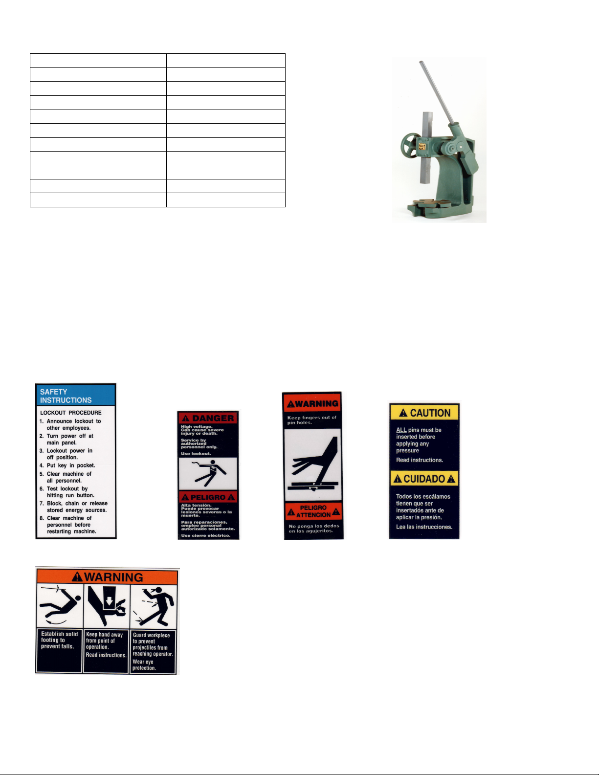
Optional side mounted arbor
Options
Part Number 76462 Part Number 84395 Part Number 84399 Part Number 84487
Part Number 300168
3/29/2010 4
Page 5
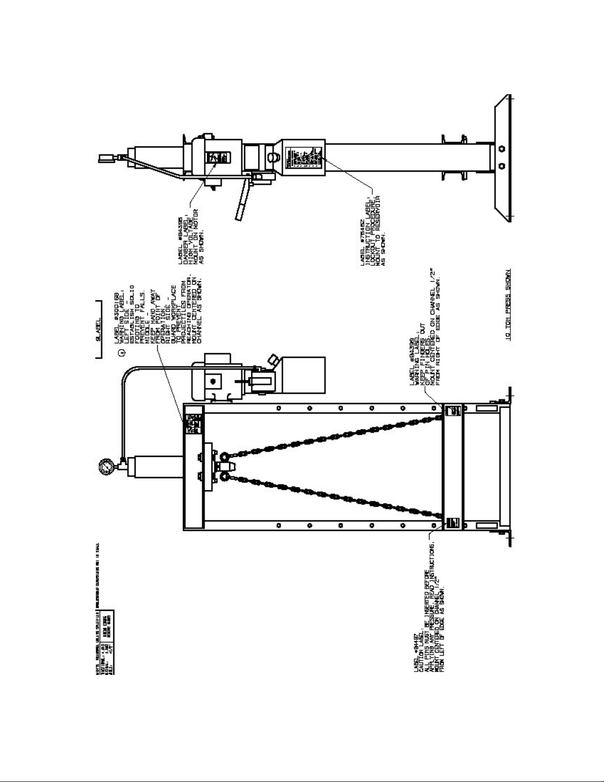
Below is a drawing showing the location of all safety labels on this press.
3/29/2010 5
Page 6

This machine is not designed for stripping operations. Personal injury or machine
damage can result.
Press set-up
Installation Instructions
Your new Dake Press has been packaged in a manner to prevent damage to any critical components; some
assembly will be required. All parts in the accessory box are critical to the function of your press. Some presses
may be pre assembled.
NOTE: FOR EASE OF ASSEMBLY LEAVE THE PRESS FRAME MOUNTED ON THE SHIPPING SKID
1. Remove plastic from the machine.
2. Open the box and you will see a pumping unit, with the press still laying on its side. Locate the four holes
on the side of the press facing up.
3. Place the pumping unit on the side of the press with the mounting bracket facing down, making sure the
holes all line up.
4. There are four bolts, washers and nuts in a bag, in the box. Put the bolts in the holes using the washers
and nuts. Make sure all nuts and bolts are tight.
5. With the press lying on its side fill the reservoir with DTE 24 Mobile oil or equivalent.
6. Look at picture on the next page to install all the fittings.
WARNING!!!!
Be sure all bolts and fittings are tight before operating this pumping unit, personal injury could result.
3/29/2010 6
Page 7

How to install the fittings on your new hydraulic press
the A port.
1
Cylinder
4
A Port
B Port
Hydraulic hose
connects here and to
2
Hydraulic hose connects here and
to the B port.
3
1 72050
2 73425
3 72047
4 10 ton 301315
25 ton 301316
50 ton 302179
5 69671
6 72402
7 302183
8 302061
5
6
8
WARNING!!!
Be sure all fittings and bolts are tight.
Do not over tighten fittings or bolts.
Joy stick valve mounts
here. It only fits one
way.
7
3/29/2010 7
Page 8

Wiring Instructions
WARNING!!!!
A licensed qualified electrician that follows all state and local laws must wire and install the electrics on
this machine.
110 Volt
WARNING!!!!!
This machine must have a designated 30 amp drop for 110 volts.
1. For 110 volts this machine is ready to plug in. The machine can be wired 220 volt single phase. Always
follow the wiring diagram provided in the motor cover when converting to 220 volt single phase. A cord
and plug that is rated for the specified voltage and amperage must be used. This rating is located on the
motor.
WARNING!!!!
It is the responsibility of the installer to make sure the motor is wired correctly for the voltage needed.
Damage to motor could result.
220 Volt single phases 17.2 amps
WARNING!!!!
A licensed qualified electrician that follows all state and local laws must wire and install the electrics on
this machine.
WARNING!!!!!
This Machine new is shipped out as a 110 volt machine. If the wiring must be changed to suit
220 volts single phase.
1. The leads on the motor must be changed to fit 220 volts 17.2 Amps, follow the diagram on the
motor.
2. Install plug and wire that fits the rating on the motor, this plug and wire must be rated for the
voltage and amperage listed on the motor.
Operation
WARNING!!!!!!
If a 110 volt power supply will be used. A designated 30 amp drop must be supplied; this press will not
operate correctly without the 30 amps.
1. Fill the reservoir with 3 gallons of Mobil DTE 24 hydraulic fluid or its equivalent AW 32.
2. Turn the on / off power switch (toggle switch) to the “on” position (up).
3. Move the control lever down, this will advance the ram in the downward position.
4. Release the control lever and the ram will stop moving.
5. Move the control lever handle to the up position and the ram will move up.
3/29/2010 8
Page 9

6. When the press is new be sure to move the ram up and down to work out any air that may be in the system.
Lubrication
Keep all working parts of the press well oiled for easier operation. Also, keep a light film of oil over the entire
surface of the ram to prevent rust.
WARNING!!!!
This press is not intended for stripping operations! Personal injury or machine damage can result.
WARNING!!!!
Only use Hydraulic oil in this machine DTE 24 hydraulic oil is recommended.
Do not use transmission fluid in this press, the warranty will be void and this fluid will damage the seals.
3/29/2010 9
Page 10

3/29/2010 10
Page 11

1
1
4
4
4
4
1
1
4
4
4
4
2
4
4
1
6
1
6
1
2
1
4
1
4
1
4
1
4
1
2
2
2
2
4
1
2
FORCE 50 DA HYDRAULIC PRESS
PARTS LIST
Item # Qty Description Part # Item # Qty. Description Part #
1
2
3
4
5
6
7
8
9
10
11
12
13
14
15
16
17
18
19
Frame 50 Ton 87137 20
Hex Cap Screw 1/2"-13x3 1/4" lg 43356 21
Channel Washer 1/2" 43657 22
Work head Assembly 716547 23
Lock Washer 1/2" 43647 24
Hex Nut 1/2"-13 43916 25
Base Angle 566 26
Hex Cap Screw 1/2"-13NC X 1
1/2" lg 43349 27
Table Pin 569 28
Retaining Ring 43980 29
Table Channel 706945 30
Lock Washer 1/2" 43647 31
Hex Nut 1/2"-13 43916 32
Table Bolts 79983 33
Table Spacer 86488 34
Shackle 301884 35
Chain 301881 36
Spring Snap 301882 37
Eye Bolt 301880
Nose Piece 87138
Lock Washer 5/8" 43648
Hex Nut 5/8"x11 43917
Hydraulic Power Unit 301856
Hex Cap Screw 5/16"18 NCx1/2"lg
Lock Washer 5/16" 43644
Hex Nut 5/16"-18 43911
Label 301879
Label 84487
Label 84399
Label 300168
Label 76462
Label 84395
Name Plate 301856
Label 76936
Table Plate 702
V-Block 336
Dake Name Plate 81002
43313
3/29/2010 11
Page 12

3/29/2010 12
Page 13

3/29/2010 13
Page 14

3/29/2010 14
 Loading...