

Page 1
724 Robbins Road
Grand Haven, Michigan 49417
616-842-7110 Phone 800-937-3253
616-842-0859 Fax 800-846-3253
Web: www.dakecorp.com
E-mail : customerservice@dakecorp.com
technicalsupport@dakecorp.com
Dura Press Models
FORCE 10 & FORCE 20
Use and Maintenance Manual
Hydraulic Press-Manual Pump
Model No: _________________
Serial No: _________________
Force 10M /Force 20M1
1 06/10
Page 2

Section I
INTRODUCTION
1. This manual has been created by DAKE to give the Customer all the necessary
information for regular use and correct maintenance of the hydraulic presses in
the DURA PRESS series. It contains the use and maintenance instructions as
well as the safety and calibrating instructions requiring your direct action.
2. It is advised to keep this publication in a good condition and somewhere easily
accessible to enable rapid reference in case of need or work.
3. Starting checks and maintenance must be carried out assuring the safety of the
operators; precautions are highlighted by the symbol.
4. Periodical and punctual written notes on what has been carried out in the
maintenance phase indicates meticulousness, but above all it becomes a clear
diary of what has been done and what will have to be done at the next
maintenance deadline.
5. For further information, please do not hesitate to call our Dake Technical Service
department at 1-800-846-3253, remembering to give the model name and serial
number of your press for faster response.
6. It is strictly forbidden to modify or tamper with the machine.
7. Removal, modification or tampering with the guards and safety devises of the
press will automatically forfeit warranty and relieve the manufacturer of all liability
for any damage to things and/or persons.
8. THE PRESS IS DESIGNED EXCLUSIVELY TO BE USED BY JUST ONE
OPERATOR.
9. It is advised to read the next section carefully: List of safety checks.
Force 10M /Force 20M2
2 06/10
Page 3

Section II
LIST OF SAFETY CHECKS
ALWAYS ACT WITH
CAUTION
ATTENTION
PRECAUTION
Read the rest of this section very carefully before proceeding to read the
following sections.
CAUTION general
When working always pay attention and be alert. Be careful. Be aware of possible
hazards.
CAUTION regulations
Observe the law and regulations of the premises regarding you and your machine.
CAUTION clothing
Injury may occur if you do not wear suitable clothing. Loose clothing may get caught up
in the machinery. Wear protective clothing suitable for the work. Examples: rigid
helmet, safety shoes, safety earmuffs, close-fitting overalls, industrial gloves, etc. Keep
cuffs buttoned. Do not wear a tie or scarf, or long hair.
ATTENTION tools
Always check that your tools are in good condition and that the tools are suitable for the
work to make (ex. don’t use the pliers as hammers etc.)
ATTENTION repairs
Don’t make repairs or any other service that you are not familiar with.
ATTENTION tampering
It is severely forbidden to modify or to tamper with press parts that can alter the
standard working.
CAUTION hydraulic hoses
Hydraulic hoses may be the cause of accidents. Regularly check such hoses looking
for:
Damaged fittings
Outer coverings worn by rubber
Swollen outer coverings
Bent or crushed hoses
And anything else that may be a hazard.
Force 10M /Force 20M3
3 06/10
Page 4

CAUTION pressure pipes
The flexible or metal pipes of a system may hold fluids under pressure even with the
system switched off. Before dismantling them, check on the diagram whether the
section could be under pressure. In any case, loosen the fittings slowly.
CAUTION hydraulic oil
Very fine jets of high-pressure hydraulic oil can penetrate the skin: do not use your
fingers to detect any leaks of hydraulic oil, neither put your face close to them, but use a
piece of cardboard to check for any leaks on them.
If hydraulic oil penetrates into your skin, get treatment from a doctor immediately.
CAUTION o-rings and gaskets
Gaskets and o-rings fitted incorrectly, damaged or worn may cause leaks and
accidents. Do not use thinners, solvents or acids close to o-rings and gaskets.
CAUTION operator
For no reason whatsoever must the operator have their hands in the area of the ram
during the pressing operation, on the equipment used.
According to new legislation, the employer will have to check that the operator
has understood these notices.
Force 10M /Force 20M4
4 06/10
Page 5

Section III
TABLE OF CONTENTS
SECTION I INTRODUCTION
SECTION II LIST OF SAFETY CHECKS
SECTION III TABLE OF CONTENTS
SECTION 1.0 GENERAL SAFETY INSTRUCTIONS
1.1 General instructions and definitions
1.2 Description
1.3 Use
1.4 Press identification
1.5 Safety labels
1.6 General safety instructions
SECTION 2.0 TECHNICAL DATA SHEET
2.1 Cylinder and spare parts section
2.2 Manual pump and spare parts section
SECTION 3.0 UNPACKING
3.1 Disposing of the packing
SECTION 4.0 HANDLING, TRANSPORTING AND POSITIONING
4.1 Notices for handling and transporting
4.2 Positioning the press
SECTION 5.0 COMMISSIONING AND START-UP
5.1 Filling the press with oil
5.2 Starting the machine
5.3 Discharging the air
5.4 Maximum pressure adjustment
SECTION 6.0 SAFETY INSTRUCTIONS
SECTION 7.0 OPERATION
7.1 Controls
7.2 Mobile table height adjustment
SECTION 8.0 MAINTENANCE
SECTION 9.0 MALFUNCTIONING, CAUSES AND REMEDIES
9.1 Cylinder malfunctioning
SECTION 10.0 PUTTING OUT OF SERVICE
SECTION 11.0 DEMOLITION AND DIVISION OF MATERIALS
Force 10M /Force 20M5
5 06/10
Page 6

Section 1.0
1.1 GENERAL INSTRUCTIONS AND DEFINITIONS
This handbook is an integral part of the product; IT MUST be carefully conserved for
future reference.
FOR ANY REQUEST FOR CLARIFICATION, ASK YOUR EMPLOYER OR THE
DAKE TECHNICAL SERVICE, AVOIDING ANY PERSONAL INITIATIVE THAT
COULD CAUSE VERY SERIOUS OR FATAL ACCIDENTS.
Before using the machine, read the warranty carefully.
DEFINITIONS:
- In this manual “right-hand side”, “left-hand side”, “forwards”,
“backwards”, “top” and “bottom” refer to the operator situated in
front of the press with the power unit to his right.
- In this manual, the units of measurement are expressed in the
international system SI (e.g. liquid capacity is expressed in liters).
1.2 DESCRIPTION
The machine described in this manual denominated HYDRAULIC PRESS Model
Dura Press has been specifically designed for use in operations where it is
necessary to use a force of compression that can be moved into different positions
even on the same part:
1. The PRESS BODY, made of high tensile carbon steel and thanks to its
monolithic structure, has considerable bending strength.
2. The HAND PUMP, placed on the right of the press allows with facility to reach
the work pressure.
3. The HYDRAULIC CYLINDER specially designed for the specific requirements
of use of the press. In addition to the special care for the internal surfaces
and of the rod, special low-friction gaskets have been used in it to optimize
the operations where special precision in the pressing action is required.
1.3 USE
The DURA PRESS/FORCE series press is mainly designed for operations of
straightening out sheet metal, profiles, and metal structures, in addition it can be
used to insert inserts (e.g. bushes, bearings, bushings, etc.), to remove inserts,
calking and all the operations where bending or cutting metal materials are not
carried out.
Other uses are not allowed unless the manufacturer expressly authorizes them.
The substance of the above mentioned operation will always be subordinate to the
maximum working capacity of the press.
THIS MACHINE IS DESTINED ONLY FOR THE USE IT HAS BEEN DESIGNED
FOR, ANY OTHER USE IS TO BE CONSIDERED IMPROPER AND THEREFORE
THE MANUFACTURER CANNOT BE HELD LIABLE FOR ANY DAMAGE
CAUSED BY ANY IMPROPER USE OR USE NOT EXPRESSLY MENTIONED IN
THIS USER’S MANUAL.
Force 10M /Force 20M6
6 06/10
Page 7
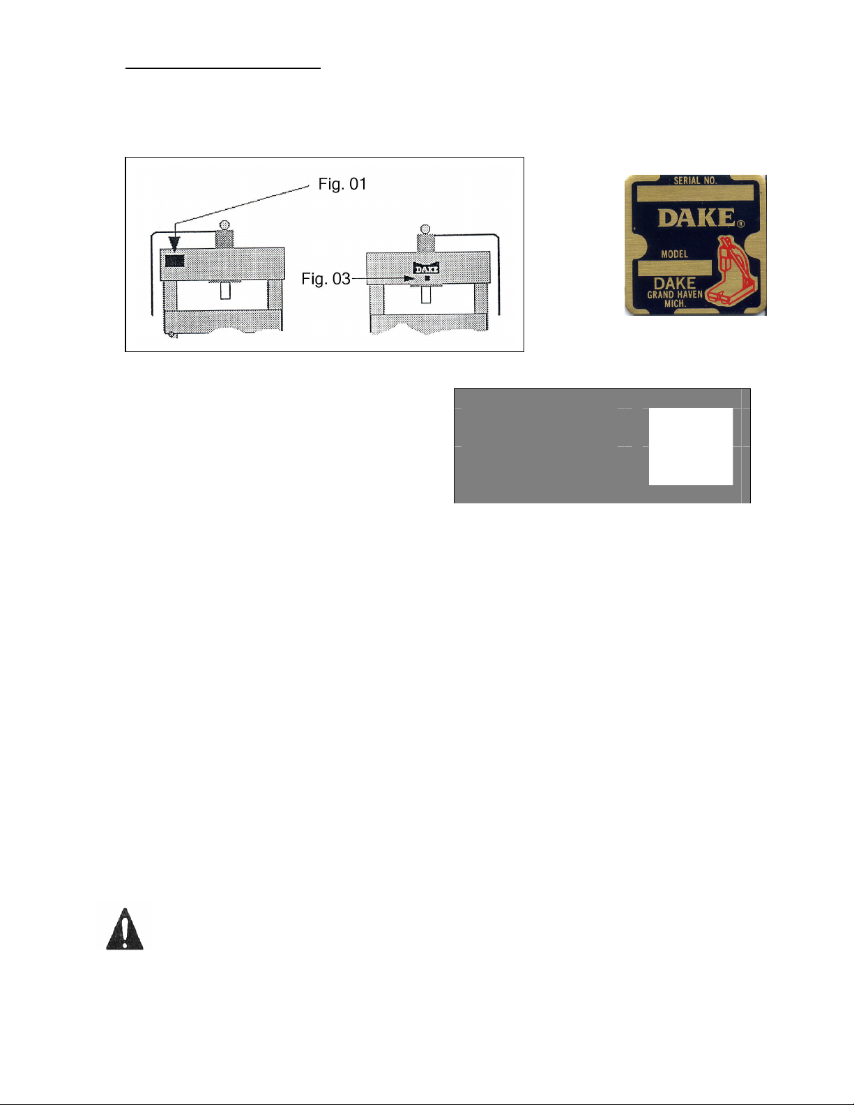
1.4 PRESS IDENTIFICATION
Fig. 03A
The press is fitted with a rating plate fixed in a visible manner on the rear as shown
in Fig. 01 below. Dake part number and serial number on front name plate shown in
Fig. 03
The rating plate (Fig. 02/03A)
shows the identification data:
- Press model
- Max. tonnage
- Max. pressure
- Press serial number/ Year of
Manufacture
- Dake part number (Tag 03)
- Serial number (Tag 03)
FOR EVERY COMMUNICATION, REQUEST FOR SERVICE OR SPARE PARTS, IT IS
ALWAYS ESSENTIAL TO QUOTE ALL THE DATA GIVEN ON THE RATING PLATE.
1.5 SAFETY LABELS
The labels on the machine highlight particular risks or provide necessary instructions
for particular operations to be carried out in safety.
Here we reproduce the labels affixed to the press and indicate their location. The
operator will have to check that these labels are present on the machine and fixed in
a stable manner. In the event of any of them missing or having deteriorated it will be
necessary to immediately notify the person in charge of safety and to forward a
request to the manufacturer.
MODEL
TON MAX
PRESSURE MAX
SERIAL NO.DAKE
Fig. 02
Part No. 607
PSS
20
200
023.98
WARNING LABELS
To the left is the safety Alert symbol. When you see these safety alert symbols on
your press, be alert to the potential for personal injury.
Follow recommended precautions and safe operating practices.
Carefully read all safety messages in these instructions and on your press
safety signs. Keep safety labels in good condition. Replace missing or damaged
safety labels. This machine is intended to be operated by one person. This person
should be conscious of the press ram movement not only for himself but also for persons in
the immediate area of the machine.
Force 10M /Force 20M7
7 06/10
Page 8

Label 300168
Label 84487
Label 84399
Label 607
Force 10M /Force 20M8
Label Placement View
84399
8 06/10
Page 9

1.6 GENERAL SAFETY INSTRUCTIONS
Use of the press is allowed exclusively for trained and authorized
personnel.
When you leave the machine, even if only for a moment, make sure it is not
in the pressing phase, dangerous for you and for others.
In the event of confusion or uncertainty in the manner of operation to be
made, refer to the user’s manual or call qualified personnel to resolve your
doubts.
Operate the manual pump only from the working position that is in front of
the hydraulic power unit.
It is forbidden to use equipment or carry out operations that may have even
the slightest chance of projecting splinters or parts of equipment.
Section 2.0
2.0 TECHNICAL DATA SHEET
Below we give a table summarizing the technical-dimensional particulars of the
DURA series Presses.
Model
Dura
Press
Force 10 10 20” 4” 6” 36” 31 x 19” 71” 350
Force 20 20 20” 4” 6” 36” 31 x 19” 71” 485
Ton
Max.
Width
between
Uprights
Width
between
Table
Channels
Max.
Ram
Travel
Max.
Ram to
Table
Base
(w x d)
Height Weight
lbs
Model
Dura
Press
Force 10 60 mm 12 mm
Force 20 80 mm 12 mm
Bore Thread Hole
size
MAXIMUM OPERATING PRESSURE FOR ALL MODELS 350 bars.
Force 10M /Force 20M9
9 06/10
Page 10

2.1 CYLINDER AND SPARE PARTS SECTION
Model Force 10M & Force 20M Breakdown
1
3
2
Item
No
1 Gauge Bar 300357 300358
Gauge in tons 301723 301722
2 Hand Pump - Complete 300366 301485
Hydraulic Cylinder
3
Complete
4 Piston Gasket 300796 301558
5 Spring 300797 301560
6 Head Scraper 300798 301561
Fitting for gauge 301888 301888
Description
Part Number
Force
10M
300652 301343
Force
20M
Force 10M /Force 20M10
10 06/10
Page 11

Model Force 10M & Force 20M Breakdown
Hand Pump Assembly
Item No Description
12 Piston Pump 302367 302367
2 Handwheel 302368 302368
20:29 Valve 302369 302369
31-32-33 Valve 302370 302370
30 Filter N/A N/A
34 Rod assembly 302373 302373
6 Spring 302372 302346
5 Cap 302371 302371
25 Tap Screw N/A N/A
Complete Pump 300366 301485
Gasket Repair Kit 301327 301542
Linkage Assembly (Item 9,10,11,15,16,34)
Relief Valve (Item 1,2,3,4,5) 301576 -Relief Valve 4NV -- 301573
* If n/a is shown must replace entire pump
Section 3.0
Force 10M Force 20M
Part Number
301575 301574
Force 10M /Force 20M11
11 06/10
Page 12

3.0 UNPACKING
If the machine is supplied wrapped in plastic sheet, any accessories, spare parts
and expendables are packed in cardboard boxes and positioned on top of the
worktable.
To remove the packing, cut the plastic wrap, taking care not to damage the machine
or cardboard box.
Remove any accessories from on top of the worktable, check the contents
correspond to the order and to the accompanying documentation.
After removing the plastic, unbolt the lag bolts from the skid.
For handling and transport, please refer to Section 4.0.
3.1 DISPOSING OF THE PACKING
The packing will have to be disposed of by the purchaser in compliance with their
local regulations.
The elements comprising the packing (e.g. plastic bags, polystyrene, nails, nylon,
etc.) MUST NOT be left within the reach of children as they are a source of danger
for them.
CLAIMS SHALL NOT BE ACCEPTED IN THE EVENT OF THE GOODS NOT
BEING IN CONFORMITY WITH THE ORDER OR WITH THE ACCOMPANYING
DOCUMENTS IF THEY ARE NOT NOTIFIED WITHIN FIVE DAYS OF THE
DATE OF RECEIVING THE GOODS.
Force 10M /Force 20M12
12 06/10
Page 13

Section 4.0
4.0 HANDLING, TRANSPORT AND POSITIONING
For handling the packed machine, as described above
(see section 3.0), it is necessary to use special lifting
equipment whose maximum lifting capacity must be no
lower than the total weight of the press.
THE TOTAL WEIGHT OF THE PRESS PLUS PACKING
IS SHOWN ON THE ADHESIVE TABS PLACED ON
THE PACKING AND ON THE ACCOMPANYING
DOCUMENTS.
For loading and unloading the machine, lifting straps are
to be used positioned as shown in Fig. 04.
4.1 NOTICES FOR HANDLING AND TRANSPORT
Loading and unloading will have to be done with lifting straps in conformity with and
according to the instructions of the above paragraph, in addition check:
Check that the straps are made in conformity with safety regulations and they
have attached the relative plates certifying they are in conformity with the standards.
CHECK THAT THE MAXIMUM CAPACITY OF EACH STRAP IS GREATER
THAN THE TOTAL WEIGHT OF THE PRESS.
Check that the straps are in a good state of repair.
It is forbidden for things and/or persons to stand close to the machine, the
unloading or loading area, and the means of transport during the loading and
unloading phases.
Do not make any sudden movements with the lifting equipment while lifting or
lowering the load.
Pay the utmost attention during all handling operations so that the press and in
particular the hydraulic power unit does not get damaged.
Observe the in-house provisions concerning lifting and handling.
IT IS FORBIDDEN TO APPROACH OR PASS UNDER HANGING LOADS.
THE MANUFACTURER DECLINES ALL LIABILITY FOR ANY DAMAGE CAUSED
BY ANY ACTION DURING THE PHASE OF UNLOADING AND LOADING THE
PRESS.
Force 10M /Force 20M13
13 06/10
Page 14

4.2 POSITIONING THE PRESS
Simple precautions are necessary for correctly positioning the press. Always
consider the safety aspect not only in relation to the work carried out with the press,
but also to the dangers originated by the other machines in the workplace. Before
positioning, check that
- The floor is suitable for positioning the press that is it has no holes or
subsiding portions, and that its capacity is sufficient to sustain the
weight of the press plus the weight of the accessory parts and of any
piece to be processed if of large dimensions, considering an
appropriate coefficient of safety.
- Do not do the positioning on unstable or non-compact surfaces
(e.g. on gravel or grit, beaten earth, sand, etc.).
- PAY THE UTMOST ATTENTION TO OVERHEAD ELECTRICITY
LINES.
- Check beforehand the position of any overhead electricity lines
and mark them with special warning cards.
- Always consider a suitable distance from the sliding paths for the
means of transport, elevators, transpallets, etc., sudden and
unexpected sources of danger.
- Check that the position identified is always served by adequate lifting
systems.
- Pay the utmost attention to handling the lifting systems (e.g. overhead
traveling cranes, hoists, transpallets, fork-lift trucks, cranes, jib cranes,
etc.)
After identifying the most suitable place for positioning, follow the instructions for
handling of Section 5.0, mark a square on the floor with YELLOW paint (highly
resistant to abrasion) around the perimeter of the press as shown by the diagram
in Fig. 06.
The area highlighted in this way will indicate the area of caution for the lifting
equipment and the personnel nearby.
Force 10M /Force 20M14
14 06/10
Page 15

Section 5.0
5.0 COMMISSIONING AND STARTING
This section describes the operations to be followed on commissioning along with
some advice for starting the machine for the first time.
5.1 FILLING THE PRESS WITH OIL
To fill the press, use exclusively the oils indicated in the table or ones of equivalent
reliability. The choice must be made considering the environmental conditions and
the operating features of the press.
Manufacturer
Mobil DTE 24 DTE 25 DTE 26
DIN 51524 H-LP 32 H-LP 46 H-LP 68
Castrol Hysoin AWS 32 Hysoin AWS 46 Hysoin AWS 68
ESSO Nuto H 32 Nuto H 46 Nuto H 68
Shell Tellus 32 Tellus 46 Tellus 68
Chevron EP Hydr. Oil 32 EP Hydr. Oil 46 EP Hydr. Oil 68
A B C
Choose the type of oil (column A, B, C) on the basis of the average working
temperature, for temperate climates the reference column in “B”. For operating
conditions in colder climates user column “A”, for warmer climates select column “C”.
5.2 FIRST STARTING
The press was shipped without oil.
After you have filled up the tank you have to stroke the hand pump until the ram is
fully extended out of the cylinder, release the wheel under the pump to return the
ram. You have to verify the oil level in the tank and if needed refill the tank. You
have to repeat the above-mentioned operation sometimes to bleed the air from the
system. See Air Discharge Section 5.3.
The level of oil in the tank may fall on starting, because of:
- absorption of volume by the cylinder
- absorption of volume by the pumping unit
- discharge of air bubbles remaining in the piping
It is necessary to top off the level of oil bringing it up to the correct height.
Force 10M /Force 20M15
15 06/10
Page 16

5.3 AIR DISCHARGE
After the first start-up, or after maintenance carried out on elements of the system
(e.g. cylinders, filters, pipes, changing oil) a considerable quantity of air may be
present in the circuit.
Irregular operation, noise, and/or uneven cylinder movement highlight the presence
of air.
It is necessary to discharge the air as follows:
- Pump ram down to the maximum stroke.
- Loosen the upper nipple of the press cylinder and wrap it in a cloth to
avoid oil splashes.
- Stroke the hand pump to remove the air.
- Verify that all the air has been bled out of the system when only oil is
expelled from the fitting.
- Tighten the nipple.
This operation must be continued until oil is completely free of air bubbles or froth.
After discharging the air, it is necessary to top off the oil level in the unit.
5.4 MAXIMUM PRESSURE ADJUSTMENT
The maximum work pressure of the press is adjusted by pressure regulator valve
suitably set and sealed with lead.
DAKE DECLINES ALL LIABILITY FOR DAMAGE TO THINGS AND/OR
PERSONS CAUSED BY TAMPERING WITH THE PRESSURE CONTROL VALVE
FITTED ON THE UNIT.
Force 10M /Force 20M16
16 06/10
Page 17

Section 6.0
6.0 SAFETY INSTRUCTIONS
THE MANUFACTURER DECLINES ALL LIABILITY FOR
DAMAGE TO THINGS OR PERSONS CAUSED BY NONOBSERVANCE OF THE SAFETY INSTRUCTIONS GIVEN IN
THIS MANUAL WHICH SUPPLEMENT THE CURRENT LEGAL
REGULATIONS IN WORKPLACES.
IT IS EXTREMELY IMPORTANT FOR THE OPERATOR TO UNDERSTAND ALL
THE SAFETY INSTRUCTIONS LISTED BELOW IN ORDER TO PREVENT
DAMAGE TO THEMSELVES, TO THINGS OR TO OTHERS.
A machine not subject to regular maintenance is a danger for the operator
and for the persons working nearby. To ensure safe and efficient operation of
the machine, check that the maintenance schedule is regularly observed.
It is strictly forbidden to tamper with, modify, or elaborate parts of the
machine that alter its regular operation.
The press is designed exclusively for use by a single operator.
Use of the press is reserved exclusively for authorized and qualified
personnel informed about the risks deriving from its use.
Before operating the machine, the operator will check that there is no
equipment or persons in the immediate vicinity of the machine whose
presence may be dangerous for themselves and for others.
All work requiring the piece to be pressed to be supported by the operator
is forbidden.
It is necessary to arrange suitable supporting and positioning equipment
for the pieces to be pressed.
It is strictly forbidden to press, cut, draw, and do anything else with pieces
whose dimensions or physical nature may explode or product splinters.
In the event of there being the slightest possibility of the pressed piece
exploding the user is obliged to arrange a protective barrier of adequate
dimensions and substance (e.g. polycarbonate) all around the press to protect
the personnel present, and to position an additional partition between the
control area and the work area to protect the operator.
Force 10M /Force 20M17
17 06/10
Page 18

Section 7.0
7.0 OPERATION
Before starting any operations, make sure there are no other persons in the
immediate vicinity of the machine.
IT IS STRICTLY FORBIDDEN TO PASS UNDER THE WORK TABLE.
7.1 CONTROLS
To make the press work you have to stroke the pump control lever.
The feed speed of the cylinder and the pressure will depend on the driving speed of
the pump control lever. The pressure starts to rise when the cylinder shaft is in
contact with the piece of press, continuing with the pump action the pressure rises
until to have the necessary valve to make the operation.
For the ram to retract, loosen the valve placed under the pump control lever. The
cylinder is equipped with a spring for the ram return.
7.2 HEIGHT ADJUSTMENT OF THE MOVABLE BASE
To get very good use of the press it is necessary to place the worktable at a correct
height depending on the operation to make and on the tooling to use.
1. To the size of the part to be pressed.
2. To any tooling placed on the movable table.
3. With the help of a second worker to lift the movable table.
4. To take away the pins and to place them in the holes of the correct height.
5. To lower slowly the worktable onto the pins.
6. To verify the positioning of the table and of the pins.
If the work position you wish corresponds with the max. width of the work size it is
not necessary to place the pins (that will be placed in a dry place) because we have
foreseen and prepared stops suitably welded to the stanchions.
Force 10M /Force 20M18
18 06/10
Page 19

Section 8.0
8.0 MAINTENANCE
AUTHORIZED AND TRAINED PERSONNEL MUST CARRY OUT ROUTINE
MAINTENANCE OPERATIONS.
ALL MAINTENANCE OR CLEANING OPERATIONS MUST BE DONE WITH THE
MASTER SWITCH OFF. (IF EQUIPPED)
SPECIAL MAINTENANCE OPERATIONS (REPAIRS) MUST BE CARRIED OUT BY
THE MANUFACTURER’S PERSONNEL ON THE PREMISES OF THE
MANUFACTURER OR BY SUITABLY TRAINED AND SPECIALIZED PERSONNEL
UPON AUTHORIZATION BY THE MANUFACTURER.
Routine maintenance operations apply to the mechanical part of this appliance, the
only special prescriptions concern checking the oil level, the characteristics of the
fluid used (and possible replacement in the case of its deterioration).
It is a good rule to take note of maintenance work to help you remember all the
work carried out on the unit.
8.1 OIL LEVEL
Check the level of oil every month through the oil fill cap hole on the top of the oil
tank. Visual inspection of the oil level should be approximately ½” below the top of
the tank.
Any topping off has to be done with the same type of and clean oil used in the filling
phase of the system and with the same procedures as regards cleaning the fluid.
It is advised to note the type of oil used on a card affixed onto the unit or on the last
few pages of this manual, containing pre-printed tables to be filled in.
If topping off turns out to be too frequent, check for leaks in the system.
8.2 CHANGING AND DISPOSING OF THE OIL
The oil will have to be changed periodically every 2000 operating hours or at
least once a year.
Changing the oil, and therefore disposing of it, will have to be done in conformity
with the law as hydraulic oil is considered special waste. Call authorized firms for
the disposal of special wastes.
DO NOT DISPERSE SPENT OIL INTO THE ENVIRONMENT
Take care while handling oil, excessive or extended contact can cause irritation. In
this case, wash the area involved with plenty of water and soap or special detergent.
Force 10M /Force 20M19
19 06/10
Page 20

8.3 CLEANING
CARRY OUT THE CLEANING OPERATIONS EVERY WEEK.
It is a good rule to carry out periodical cleaning of the press in order to eliminate
foreign bodies (e.g. dust, extraneous and dirty substances, etc.).
Eliminate all foreign bodies from the piston rod that could damage both the surface
of the rod and the cylinder gaskets.
While cleaning, use detergent substances that are not harmful, do not pollute and
are in conformity with the law.
While cleaning, prevent shaking with hands, wear protective gloves and use brushes
or oilers to lubricate the guides.
Do not use solvents or aggressive acids.
Section 9.0
9.0 MALFUNCTIONING, CAUSES and REMEDIES
9.1 CYLINDER MALFUNCTIONING
MALFUNCTION ORIGIN REMEDY
The cylinder moves
irregularly
Cylinder will not move - Cylinder gaskets
Cylinder leaks oil - Head gasket damaged or
Cylinder will not press - Lack of pressure from
Force 10M /Force 20M20
- Air in the pump
- Air in the circuit
- Damage cylinder gaskets
- Damage or worm pump
- Sequence valve jammed
- Delivery pipe clogged or
choked.
completely damaged
- Blocked distributor
- Damaged pump
worn
pump
- Pressure control valve set
low
* Call Dake Technical Service 1-800-937-3253
20 06/10
CYLINDERS
- Bleed the air
- Bleed the air
- Replace the gaskets
- Replace the pump
- Recondition seq. valve
- Check pipes
- Replace
- Recondition distributor
- Recondition or replace
- Replace
- Recondition pump
- Set valve
*
*
*
*
*
Page 21

Section 10.0
10.0 PUTTING OUT OF SERVICE
In the case of putting away for a long period it is necessary to empty the unit of oil
and protect it suitably so there is no dust, moisture, or other foreign bodies, exposed
to the unit that can damage the parts of the unit.
When putting into operation after a period of storage, meticulously follow ALL
the indications of Section 5.0.
Section 11.0
11.0 DEMOLITION AND DIVISION OF MATERIALS
If you are not going to use the appliance any more, it is recommended to make it
inoperative by removing the oil contained in the tank and eliminating the oil
remaining in the cylinder, pipes, pump body and valves.
When going for demolition the press must be treated as special waste, it must
therefore be split up into its homogeneous parts, these parts must be separately
disposed of in conformity with the laws in force.
724 Robbins Road
Grand Haven, Michigan 49417
616-842-7110 Phone 800-937-3253
616-842-0859 Fax 800-846-3253
Web: www.dakecorp.com
E-mail : customerservice@dakecorp.com
technicalsupport@dakecorp.com
Force 10M /Force 20M21
21 06/10
Page 22

Gauge Conversion 10 ton
Bore 60 mm = 2.362”
10 Ton 302 bar 4565 PSI
5 Ton 151 bar 2282 PSI
4 Ton 121 bar 1825 PSI
3 Ton 90 bar 1369 PSI
2 Ton 60 bar 913 PSI
1 Ton 30 bar 456 PSI
Gauge Conversion 20 ton
Bore 80 mm = 3.149”
20 Ton 340 bar 5136 PSI
15 Ton 255 bar 3852 PSI
10 Ton 170 bar 2568 PSI
5 Ton 85 bar 1284 PSI
4 Ton 68 bar 1027 PSI
3 Ton 51 bar 770 PSI
2 Ton 34 bar 514 PSI
1 Ton 17 bar 257 PSI
Force 10M /Force 20M22
22 06/10
 Loading...