

Page 1
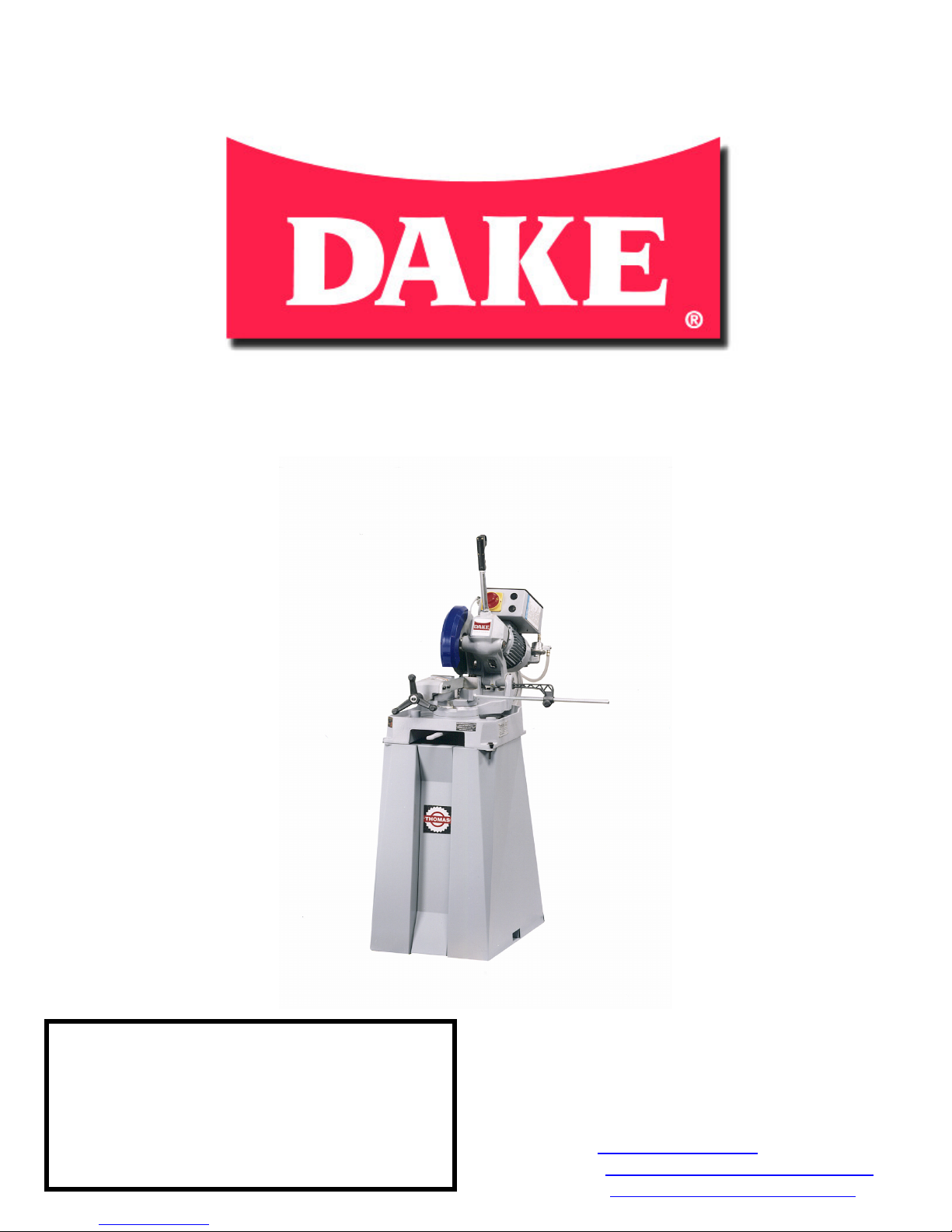
CUT 250 COLD SAW
MANUAL FOR 250 COLD SAW
MODEL::
SERIAL NUMBER:
DATE PURCHASED:
________________________________________
________________________________
______________________________
7/13/05 1
DAKE Division of JSJ
724 Robbins Road
Grand Haven, Michigan 49417
616-842-7110 Phone 800-937-3253
616-842-0859 Fax 800-846-3253
Web: www.dakecorp.com
Email: customerservice@dakecorp.com
technicalsupport@dakecorp.com
Page 2

CUT 250 COLD SAW
Accident prevention
Regulations
-This machine has been built to comply with national accident prevention regulations. Improper
use and/or tampering with the safety devices will relieve the manufacturer of all responsibility.
-Check that the voltage indicated on the plate, normally fixed to the machine motor is the same as
the line voltage.
-Check the efficiency of your electric supply making sure the machine has it’s own grounded
circuit.
-Do not operate machine without safety guards or with the electrical panel cover removed.
-Always disconnect machine from power source before changing the blade, performing
maintenance or if the machine is operating abnormally.
-Do not operate this machine without the handle and/or handle switch disconnected.
-Always wear OSHA approved safety glasses when operating this machine.
-Never put your hands or arms into the cutting area while the machine is in operation.
-Do not shift or move machine while the machine is in operation.
-Do not wear loose clothing, gloves, bracelets, rings, watches, chains or any other object
that could get caught in the machine while in operation and Tie back long hair.
-Keep the machine bed free from tools or any other object, while machine is in operation.
7/13/05 2
Page 3

CUT 250 COLD SAW
Location of safety
Covers
-Grey metal shield covering the blade.
-Blue plastic shield covering the blade.
-Black plastic cover, covering the electrical supply box.
Electrical equipment
-According to European Standard “CENELEC EN 60 204-1” which simulates modifications,
publication (IED 204-1)
-The electrical equipment ensures protection against electric shock as a result of direct or indirect
contact. The active parts of this equipment are housed in a box so that access is limited, the screws
can only be removed with a standard screwdriver.
-This equipment is protected against splashes of water and dust.
-This machine has been tested in conformity with EN 60204.
Recommendations for use
-This machine has been designed to cut metal building materials with different shapes, profiles
used in workshops and mechanical structural work.
-Only one operator is needed to use the machine.
-Before starting each cutting operation, ensure that the part is firmly gripped in the vice and that
the end is suitably supported.
-Do not use cutting blades of a different size from those stated in the cutting capacity section (next
page).
-If the cutting blade gets stuck in the work piece, release the blade ON button immediately, switch
off the machine, and open the vise slowly. Remove the part and make sure that the cutting blade
and/or its teeth are not damaged or broken.
7/13/05 3
Page 4

CUT 250 COLD SAW
-Before carrying out any repairs on the machine, consult the distributor or DAKE.
Cutting capacity
CUTTING
CAPACITY
90* 1 1/8 2 3/4 2 1/2 3½ X 1 3/4
45* 1 2 3/8 2 1/8 2 ½ X 2
-Single Phase, single speed electric motor 1HP
-Reduction gear Ratio = 1:32
-Maximum blade diameter Inches 10
-Blade speed rotation rpm 44
-Max. Vice opening Inches 4 1/8
-Machine weight without stand Pounds 176
-Machine weight with stand Pounds 238
Machine Dimensions
All Dimensions are in Inches
Instructions when you receive your machine
7/13/05 4
Page 5

CUT 250 COLD SAW
-When you receive your machine it will be wrapped in plastic (see illustration 3).
-Remove the plastic and set pedestal to the side.
-Remove wooden walls from the crate.
-There are two bolts securing the machine to the crate, remove these two bolts.
Illustration 3
Assembling the Pedestal
-Open the box and remove all pieces. You will have four large pieces with a bag of nuts and bolts
(see illustrations 4, 5 and 6)
Bag of
nuts and
bolts
Illustration 4 Illustration 5 Illustration 6
Piece 1 Piece 2 Piece 3 Piece 4
-Open the bag of nuts and bolts you will have the following contents (also see illistration7 on page
6):
2 – 13mm x 40mm bolts 2 – 13mm nuts 8 – 12mm washers
4 – 10mm x 16mm bolts 2 – 31mm washers
2 – 23mm washers 4 – 10mm bolts
7/13/05 5
Page 6

CUT 250 COLD SAW
13mm x 40mm bolt
10mm x 16mm bolt
31mm
12mm washer
washer
10mm nut
23mm
washer
Illustration 7
13mm nut
-Place both large pieces of the pedestal next to each other like in Illustration 4 on page 5.
- Take piece 4 and place between piece 1 and 2, as you will notice there are tabs on the sides, Put
these tabs in the holes of piece 1 and push down, the two pieces will snap together (see illustration
8 & 9). Do the same with piece 3.
Hole for bolt
Tab
Piece 1
Piece 4
Illustration 8 Illustration 9
-There are 4 holes on the inside of this pedestal (two on the front and two on the back side). Take
the 10mm x 16mm (see illustration 7) bolt and put one 12mm washer on it, put this bolt in the hole
located on the inside of the pedestal (see illustrations 10 & 11 next page), then put one 12mm
washer and one 10mm nut on, tighten nut as needed. Repeat this step for all four-bolt holes.
7/13/05 6
Piece 2
Page 7

CUT 250 COLD SAW
Hole on rear of
pedestal
Holes on
front of
pedestal
Illustration 10 Illustration 11
-When you finish assembling the pedestal it will look like Illustration 12.
Illustration 12
Transporting and handling
-When you receive your machine use a forklift to transport the machine.
7/13/05 7
Page 8

CUT 250 COLD SAW
-When lifting the machine use a sling.
How to mount your Cold Saw on the pedestal
-Place the machine on the pedestal so that the front of the machine is facing the front of the
pedestal (see illustration 14).
Front side of
machine
Front side of
pedestal
Front
Illustration 14 illustration 15
-Use the two remaining bolts (13mm x 40mm) and put a 31mm washer on it, put the bolt into the
front mounting hole (see illustration 15). Put a 31mm washer on the bottom side of the bolt, now
put the 13mm nut on the bolt.
-See picture below (illustration 16) to mount the second bolt on the rear side of the machine.
mounting hole
7/13/05 8
Page 9

CUT 250 COLD SAW
Rear
mounting
hole
Illustration 16
How to assemble the machine
-The following parts will be with your machine upon receiving: handle and a stock stop (see photo
on page 9).
Stock stop
Front
mounting
hole
Illustration 17
Illustration 18
Handle
Shipping bolt
Threaded hole
7/13/05 9
Page 10

CUT 250 COLD SAW
-Remove the shipping bolt (see illustration 18) and screw the handle in the hole. There is a white
plug that comes out of the handle, plug this into its receptacle located on the side of the electrical
box (see illustration 19). There is a lever on this attachment move this to the closed position as
seen on illustration 19.
Lever
Receptacle
Illustration 19
Anchoring The Machine
-Position the machine on a firm cement floor; keep a minimum distance of 2 1/2 feet from the
wall. Mount to the floor as shown in diagram
3.
Diagram 3
Instructions for electrical connection
7/13/05 10
Page 11

CUT 250 COLD SAW
-Before connecting the machine to the main power, make sure that your installation has a
disconnect box.
-The machine is not provided with an electrical plug, the customer must provide a suitable plug for
the machine. See diagram below for wire connection.
Operating your Cold Saw cut 250
3
Machine
bed
-Mix the coolant that came with the machine (Trim Sol) at a 10:1 ratio, add about a half gallon of
mixed coolant in the machine bed.
-Place the material to be cut in the vice (1) and clamp the material in place by turning the hand
wheel (2) clockwise.
-Turn the power switch clockwise to the on position (illustration below).
7/13/05 11
Page 12

CUT 250 COLD SAW
Off position ON position
-Be sure that the blade is rotating in the correct direction indicated (the blade will rotate clock
wise, be sure the blade is on correctly, also see changing the blade page 12) and check to make
sure the coolant is on.
-The machine is now ready to cut the material. Keep in mind that the cutting speed and the type of
blade, combined with a suitable descent of the head are of decisive importance for cutting quality
and machine performance.
- When starting to cut with a new blade, be sure to take out the back lash (see changing the blade)
on the blade, in order to safeguard the blade life and efficiency, the first two or three cuts must be
made while exerting a slight pressure on the part, so that the time taken to cut is about double the
normal time. Grip the handle and press the button, slowly move the head in the down position and
begin to cut the material. When you are done cutting the material, release the blade “on button”
and move the head in the up position.
Changing the blade
Warning!!!!! Before performing the following operations, the electrical supply must be
LOCKED OUT.
10mm Allen wrench
Safety guard
Bolt holding
safety guard
Blade bolt
Illustration 20
-Move the head to the upright position and remove the blue safety guard bolt (5mm Allen wrench
see illustration 20), move the safety guard in the back position.
7/13/05 12
5mm Allen wrench
6mm Allen wrench
Page 13

CUT 250 COLD SAW
On
-Always wear gloves when handling the cutting blade or any sharp object.
-Use the 10mm Allen wrench to remove the blade bolt (see illustration 20), this is a left hand
thread; turn it clockwise to loosen the bolt. Slip off the bolt and the flange that holds the blade on.
Flange pins
Flange
-When placing on a new blade be sure to clean all surfaces and that the cutting teeth are facing in
the down position (the blade turns clockwise), line the holes up on the blade with the holes on the
motor side (Clean both sides of the flange), put the flange back on, making sure the flange pins are
in line with the flange pinholes.
-Screw the blade bolt back in turning it counter clockwise, before tightening the blade be sure to
remove the back lash by pulling up on the blade in the reverse direction and holding it while
tightening the blade.
-Screw in the safety guard bolt and you are finished.
Flange
pinhole.
motor side
Motor side
Flange
Routine maintenance
If the following operations are neglected, the result will be premature wear of
the machine and poor performance.
Daily maintenance
-General cleaning of the machine, remove accumulated shavings.
-Keep coolant level full.
-Check for blade wear
-Lift the head to the up position, to avoid stress on the return spring when not is use
-Check functionality of the safety shields.
7/13/05 13
Page 14

CUT 250 COLD SAW
Weekly maintenance
-Remove metal shavings from the coolant tank
-Clean and grease the screw and the sliding guide of the vice.
-Clean the blade housing
-Sharpen the blade
Monthly maintenance
-Check tightness of the screws on the motor, the pump, the jaws and safety guard
-Check that the safety shield is not broken
-Grease the head hinge pin.
Six Month maintenance
How to change the oil in the gearbox
-Disconnect machine from the power supply
-Change the oil in the reduction unit using gear lube 80/90. We recommend MOBIL SHC635.
Plug coming from the
handle
Fill hole
for oil is
the same
hole the
handle
screws
into.
Handle
Sight level
gauge
-
Remove the handle and the plug coming from the handle to the electric box.
-Unscrew the sight level gauge; this will drain all the oil in the gearbox. Use a bucket to catch all
the oil from the gearbox.
-When oil stops coming out of the sight level hole, screw the sight level gauge back into the hole.
-Fill gearbox with 80/90-gear oil. We recommend SHC 635 MOBIL when refilling the gearbox
be sure to fill only to the middle of the sight level gauge when the cutting head is sitting level.
-Screw handle back in hole and connect the Plug coming from the handle.
Oil disposal
-The disposal of oil and coolant products are controlled by strict regulations, follow local rules and
regulations to dispose of properly.
7/13/05 14
Page 15

CUT 250 COLD SAW
Choosing a blade
First of all, the pitch of the teeth must be chosen, suitable for the material to be cut, according to
this criteria:
-Parts with a thin and/or variable section such as profiles, pipes and plate, need fine toothing, so
that the number of teeth used simultaneously cut.
-Parts with solid sections need wide spaced toothing penetration.
-Material made of soft plastic, light alloys and mild bronze also requires coarse toothing.
-Attached to the on/off switch on the machine you will find a blade pitch calculator (Part number
71756) with instructions on how to use it.
Troubleshooting
This lists the probable faults and malfunctions that could occur while the machine is being used
and suggests possible remedies for solving them.
PROBLEM
Tooth breakage
Premature disk wear
Chipped disk
7/13/05 15
PROBABLE CAUSE REMEDY
Too fast advancement
Wrong tooth pitch
Low quality blade
Ineffective gripping of the vise
Previously broken tooth left in
material
Insufficient coolant
Blade is on backwards
Incorrect blade
Insufficient coolant
Flaws in the material
Wrong tooth pitch
Decrease advancement, use
less cutting pressure
Choose a different blade
Choose a better quality blade
Tighten vise if necessary
Remove all pieces from
material
Check coolant level, Add more
if necessary
Turn blade around
Change blade for one that has
more or less teeth
Check coolant level, add more
if necessary
Reduce the cutting pressure
and/or advancement
Change blade for suitable
blade (use blade pitch
calculator)
Page 16

CUT 250 COLD SAW
Noise test
In accordance with point 1.7.4f of the Machines Directive EEC 89/392
-The microphone was located close to the operator’s head at medium height.
-The equivalent continuous acoustic pressure level was 77,6dB (A).
-The maximum level of the weighted instantaneous acoustic pressure C was always less than 130
dB.
NOTE: With the machine operating, the noise level will vary according to the different materials
being processed. The user must assess the intensity and if necessary provide the operators with the
necessary personnel protection, as required by law 277/1991.
DRAWING
PART NAME PART NUMBER
NUMBER
1 MACHINE BED AGC11070
2 REVOLVING ARM AG190046
3 REVOLVING ARM PIN AFC10029
4 REVOLVING ARM LOCKING BRUSH AFC10030
5 REVOLVING ARM LOCKING LEVER AG160022
6 SCREW TCCE M8 81110080
7 ELASTIC PIN 6 82504217
8 COUNTERVICE AG940011
9 DOWEL M6 5927 81132062
10 BAR STOP ROD ANC10046
11 BAR STOP ANC10046
12 VICE AG940012
17 OILER 5 82901005
18 VICE HAND WHEEL 47100000
19 ROLL PIN 82504217
20 VICE SCREW AFC10058
23 BURR-FREE PLATE AF940081
24 SEAL FITTER SUPPORT FLANGE ANC10072
25 SNAP RING 42 82610000
26 TANK COVER FITTER AFB80043
27 FITTER SUPPORT FLANGE ANC10071
28 SCREW TCCE M5 64180
29 WASHER 82100000
30 COOLANT ON/OFF VALVE 88600000
31 COOLANT HOSE 69102002
32 SCREW TCCE M6 81110055
33 COOLANT TANK SCREEN AFB80044
34 SCREW TSPEI M8 81120074
35 NUT M8 HEXAGONAL 81600008
36 HINGE PIN 060A0010
37 DOWEL M6 5927 81132062
38 NUT M6 HEXAGONAL 81600006
40 NUT M16 HEXAGONAL 81600016
7/13/05 16
Page 17

CUT 250 COLD SAW
41 HEAD LEVER AF190052
42 HAND GRIP 44600001
43 ANELLOSM 30-40-7 86001049
44 KEY UNI 8X7 6604 82502082
45 BLADE SHAFT AF190006
47 BLADE SHAFT FLANGE PINS AFC10013
48 BLADE SHAFT FLANGE AF19B006
49 BLADE BOLT M12X30 LEFT HAND
S1110136
THREADS
50 FIXED BLADE GUARD AG190086
51 DOWEL M16 5923 81130102
52 COOLANT TUBE AFC10091
53 BLADE GUARD AH190087
54 SNAP RING 60 82600000
55 SCREW TCCE M6 81110055
57 UPPER BLADE GUARD SUPPORT ARM AF19B090
58 SNAP RING 10 82600000
59 SAFETY GUARD SUPPORT PIN AF19B090
60 LOWER SAFETY GUARD SUPPORT
AF190088
ARM
61 SCREW TCCE M8 81110080
62 PIN 4 82504165
63 WORM WHEEL AB190042
64 DOWEL M8 5923 M8x1.25 stock room 81130082
65 WORM WHEEL RETAINING WASHER AFB8B037
66 SCREW M12 81110133
67 NUT M16 HEXAGONAL 81600016
68 WORM SCREW AF160010
70 FRONT MOTOR FLANGE AHH80004
73 MOTOR 3PH CE 74320104
73.1 MOTOR 3PH NON CE 74300104
74 MOTOR 1PH CE 74320103
74.1 MOTOR 1PH NON CE 74300103
79 HEAD GASKET AN160031
82 TESTA AG190054
83 REAR MOTOR FLANGE AHH80005
84 MOTOR FAN 74310007
85 FAN COVER AHH80006
86 SCREW TCCE M4 81701
87 BEARING 609 84101016
88 PUMP CONNECTION BOX AG190044
89 SCREW TCCE M5 72528 72528
90 COOLANT PUMP 88141000
91 SCREW TCCE M6 81110055
92 OIL PLUG 88302002
93 SPTING TOP CONNECTION 110C0012
94 HEAD RETURN SPRING AFC10021
7/13/05 17
Page 18

CUT 250 COLD SAW
95 AUXILIARY RELAY 72300000
96 REMOTE-CONTROL SWITCH 73401001
97 FUSE HOLDER 73142005
98 TRANSFORMER 30VA 73327011
99 SOCKET CONNECTOR 73600005
100 PLUG CONNECTOR 73600052
101 SWITCH 2SP CE BRETER 1167 70221013
101 SWITCH 1SP 1PH CE KEDU 70240000
102 RESET PUSH-BUTTON 70101000
103 EMERGENCY PUSH BUTTON 70101000
104 ELECTRIC BOX 230E0017
105 BOX COVER (NOT INCLUDED IN 104) NO NUMBER
106 BOX GASKET D80E0306
ELECTRIC CONPONENT BOX 1PH 68240000
WARNING LIGHT 70651000
Capacitor 302020
If you would like to order parts please contact: DAKE 724 ROBBINS ROAD, GRAND HAVEN,
MI 49417 Phone: 800-937-3253 Web: www.dakecorp.com
EMAIL: customersupport@dakecorp.com
technicalsupport@dakecop.com
7/13/05 18
Page 19

CUT 250 COLD SAW
7/13/05 19
Page 20

CUT 250 COLD SAW
7/13/05 20
Page 21

CUT 250 COLD SAW
The following labels are on the machine for your safety
and protection:
Part number 82199 Part number 84395 Part number 76462
Part number 84605
Warranty
Our products are warranted free of manufacturer’s defects for one year after delivery to the original
purchaser. Replacement parts are warranted free of manufacturer’s defects for the longer of ninety
days after delivery or the remaining warranty period for our products on which the part is installed.
Subject to the conditions hereinafter set forth, the manufacturer will repair or replace any portion
of the product that proves defective in materials or workmanship. The manufacturer retains the sole
right and option, after inspection, to determine whether to repair or replace defective equipment,
parts or components, the manufacturer will assume ownership of any defective parts replaced
under this warranty.
7/13/05 21
Page 22

CUT 250 COLD SAW
This warranty will not apply to:
(a) Units and parts which are not installed in accordance with applicable local codes,
ordinances and good trade practices;
(b) Defects or malfunctions resulting from failure to properly install, operate, or maintain the
unit in accordance with the printed instructions provided;
(c) Failure resulting from abuse, accident or negligence;
(d) Normal maintenance service and the parts used in connection with such service;
(e) Units and parts which have been altered or repaired other than by the manufacturer or as
specifically authorized by the manufacturer;
(f) Units and parts used for purposes other than for what it was designed and manufactured.
Return of warranted components
Purchasers who notify the manufacturer in writing, within the warranty period, will be issued a
Return Material Authorization Number. Any item to be repaired or replace under this warranty
must be returned to the manufacturer, at Grand Haven, Michigan or such other place as the
manufacturer man designate, freight prepaid. The packaging used for returns must be supplied by
purchaser and clearly marked with the Return Material Authorization Number.
Repair and Replacement of warranted components:
Any item covered under this warranty will be repaired or replaced free from all charges except
authorized transportation and installation labor.
This warranty is in lieu of all other warranties and no representations, guarantees, or
warranties, expressed, implied, or statutory (included, but not limited to, a warranty of
merchantability of fitness for a particular purpose) are made by manufacturer in connection
with the manufacture of sale of its products.
The remedies set forth herein are exclusive and in lieu of all other remedies and
manufacturer shall not, under any circumstances, be liable for incidental, consequential or
special damages, such as, but not limited to, damage to, or loss of, other property or
equipment, loss of profits, inconvenience, or other incidental or consequential damages of
any type or nature. The liability of the manufacturer shall not exceed the price of the product
upon which the liability is based.
No employee, distributor, or representative is authorized to change this warranty in any way
or grant any other warranty on behalf of manufacturer.
7/13/05 22
 Loading...