

Page 1

INSTRUCTIONS AND PARTS LIST FOR
Models 1-202, 1-204, 1-210, and 1-220
WARNING LABELS
To the left is the safety Alert symbol. When you see these safety alert symbols on your press,
be alert to the potential for personal injury.
Follow recommended precautions and safe operating practices.
SETTING UP THE PRESS FOR OPERATION
1. Fasten press to bench or work surface using the mounting holes provided (Item 3).
2. Connect a 3/8” air supply to the filter-regulator (Item 38) located at the rear of the press frame. CAUTION!
Air must be moisture free! Water in the air supply may damage the press beyond repair! Air line
lubrication is not required.
3. Adjust the air regulator for proper operating pressure as follows:
a. 200 pound model (1-202) at 70 psi.
b. 400 pound model (1-204) at 90 psi.
c. 1000 pound model (1-210) at 85 psi.
d. 2000 pound model at (1-220) at 100 psi.
OPERATIONS
1. Depressing both recessed buttons (Item 23) simultaneously will cause the press to close.
2. The releasing of either recessed button will cause the press to open fully.
3. The Down Stroke Stop adjustment (Item 8) is located inside the guard (Item 10). This adjustment
may be used to limit the closing of the press to any point in the stroke. Always tighten the locknut to
keep the adjustment in place. WARNING! AWAYS REPLACE THE GUARD (Item 10). NOT
DOING THIS COULD RESULT IN SERIOUS INJURY!
4. The cylinder rod of the press has a non-rotating feature that could be damaged if care is not used
when attaching tooling. Always hold the rod from rotating using a wrench on the flats above the
threads when attaching tooling or tooling adapters.
5. There are openings in each side of the control enclosure for screwdriver adjustment of the press
ram speed. The opening on the right side (looking from the front) controls the up speed and the
other one is for the down speed. Turning the screw clockwise decreases the speed.
Air Arbor Presses
Model 1-202, 1-204, 1-210 & 1-220 3/12/2008
1
Page 2
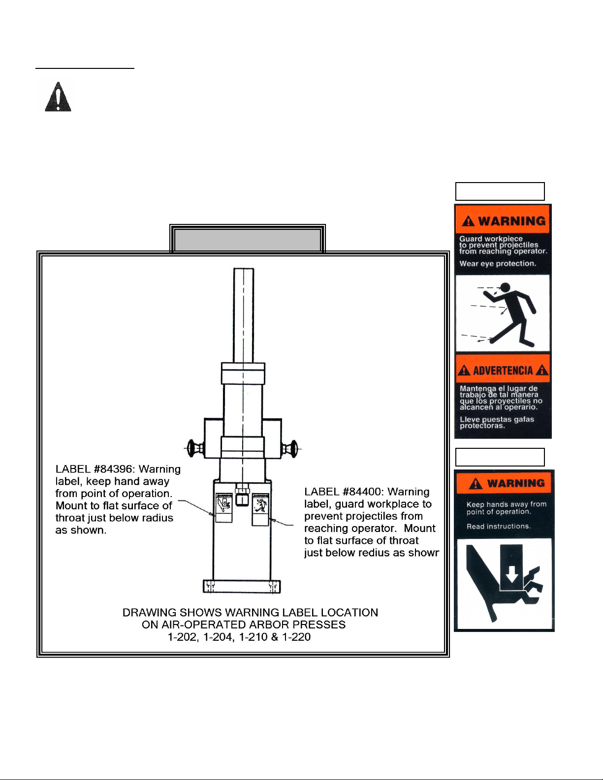
WARNING LABELS
Label 84400
Label 84396
To the left is the safety Alert symbol. When you see these safety alert symbols on your press,
be alert to the potential for personal injury.
Follow recommended precautions and safe operating practices.
Carefully read all safety messages in these instructions and on your press safety signs.
Keep safety labels in good condition. Replace missing or damaged safety labels. This machine is intended
to be operated by one person. This person should be conscious of the press ram movement not only for
himself but also for persons in the immediate area of the machine.
Label Placement View
Model 1-202, 1-204, 1-210 & 1-220 3/12/2008
2
Page 3

Model 1-202, 1-204, 1-210 & 1-220 3/12/2008
3
Page 4

Model 1-202, 1-204, 1-210 & 1-220 3/12/2008
4
Page 5

Item Part Name
Model
1-202
Model
1-204
Model
1-210
Model
1-220
1 Main Frame 67463 67472 67728 67733 1
2 Air Cylinder 67446 67473 67730 67735 1
3 Mounting Plate 67461 67474 67731 67734 1
3/8”-16 x 1” Hex Cap Screw 43328 - - - 4
1/2”-13 x 1-1/4” Hex Cap Screw - 43348 - - 4
4
3/4”-10 x 3/4” Hex Cap Screw - - 43372 - 4
1”-8 x 1/2” Hex Cap Screw - - - 43383 4
3/8” Lock Washer 43645 - - - 4
1/2” Lock Washer - 43647 - - 4
5
3/4” Lock Washer - - 43649 - 4
1” Lock Washer - - - 43650 4
5/16”-18 x 2” 43320 - - - 4
3/8”-16 x 2-3/4” Hex Cap Screw - 43336 - - 4
6
3/8”-15 x 3-1/4” Hex Cap Screw - - 43339 - 4
1/2”-13 x 4-1/2” Hex Cap Screw - - - 43359 4
5/16” Lock Washer 43644 - - - 4
7
3/8” Lock Washer - 43645 43645 - 4
1/2” Lock Washer - - - 43647 4
8 Stroke Control 67464 67464 67732 67732 1
1/2"-20 Hex, Jam Nut 43941 43941 - - 1
9
3/4”-16 Hex, Jam Nut - - 43946 43946 1
10 Stroke Control Guard 67462 67462 67729 67729 1
1/2”-20 Hex, Jam Nut 43941 43941 - - 1
11
3/4”-16 Hex, Jam Nut - - 43946 43946 1
12 Nose Piece 68391 68391 68392 68392 1
1/4” Male Elbow Conn. – Brass 60467 60467 - - 2
13
3/8” Male Elbow Conn. – Brass - - 60470 60470 2
14 1/4” Male Tube Conn. – Brass 50790 50790 50790 50790 2
1/4" Tube Line (Top of air cylinder to subplate) 67764 67764 - - 1
1/4” Tube Line (Bottom of cylinder to subplate) 67765 67765 - - 1
15
3/8” Tube Line (Top of air cylinder to subplate) - - 67762 67762 1
3/8” Tube Line (Bottom of cylinder to subplate) - - 68486 68486 1
1/8” Tube Line (R.H. air valve to element) 68487 68487 68487 68487 1
16
1/8” Tube Line (L.H. air valve to element) 68488 68488 68488 68488 1
1/8” Tube Line (R.H. air valve to tee) 68489 68489 68489 68489 1
17
1/8” Tube Line (L.H. air valve to tee) 68490 68490 68490 68490 1
18 1/8” Tube Line (Subplate to element) 68491 68491 68491 68491 1
19 #10-24 x 1/4” Phillips Hd. Machine Screw 60477 60477 60477 60477 2
20 #10-32 x 1/2" Slotted Machine Screw 43858 43858 43858 43858 4
21 Control Enclosure 68390 68390 68390 68390 1
22 1/4"-20 x 1/2” Hex Cap Screw 2
23 Control Button 67467 67467 67467 57467 2
24 10#-32 x 3/4" Slotted Machine Screw 4
25 1/4"-20 x 1-3/4” Hex Cap Screw 43865 43862 43864 43864 2
26 1/4"-20 Hex Nut - - 43946 43946 2
27 3/8” x 1/8” Hex Bushing – Brass 60478 60478 60478 60478 1
28 Logic Element 67453 67453 67453 67453 1
29 #10-32 Hex Nut 43907 43907 43907 43907 4
30 3/8” x 1/4" Hex Bushing – Brass 50790 50790 50790 50790 1
31 Manifold Subplate 67470 67470 67470 67470 1
Qty
Model 1-202, 1-204, 1-210 & 1-220 3/12/2008
5
Page 6

Item Part Name
Model
1-202
Model
1-204
Model
1-210
Model
1-220
32 1/4" Pipe Nipple – Brass 44511 44511 44511 44511 1
33 1/8” Pipe Plug – Brass 60469 60469 60469 60469 2
34 Stack Speed Control 62031 62031 62031 62031 1
35 4-Way Air Valve 67468 67468 67468 67468 1
36 1/4” Lock Washer 43643 43643 - - 2
37 1/4” Pipe Plug – Brass 33771 33771 33771 33771 2
38 Filter – Regulator 62552 62552 62552 62552 1
39 1/8” Male Elbow Conn. – Brass 60463 60463 60463 60463 4
40 1/8” Male Branch Tee – Brass 60468 60468 60468 60468 1
41 1/8” Male Tube Conn. – Brass 60464 60464 60464 60464 4
Qty
724 Robbins Road
Grand Haven, Michigan 49417
616-842-7110 Phone 800-937-3253
616-842-0859 Fax 800-846-3253
Web: www.dakecorp.com
E-mail : customerservice@dakecorp.com
technicalsupport@dakecorp.com
Model 1-202, 1-204, 1-210 & 1-220 3/12/2008
6
 Loading...