

Page 1
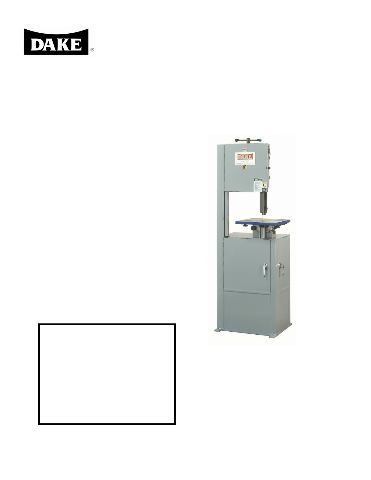
VERTICAL BAND SAWS
INSTRUCTION MANUAL AND PARTS LIST
MODEL 14-10
DAKE/PARMA
WHEN ORDERING PARTS
GIVE COMPLETE SERIAL NUMBER OF MACHINE
GIVE PART NUMBER AND NAME
GIVE AMOUNT REQUIRED
MODEL: 14-10________________________________
SERIAL NUMBER: _____________________________
DATE PURCHASED: ___________________________
DAKE Division of JSJ
724 Robbins Road
Grand Haven, MI 49417
Phone: 616-842-7110 800-937-3253
Fax: 616-842-0859 800-846-3253
E-mail: technicalservice@dakecorp.com
Website: www.dakecorp.com
5/13/07
Model 14-10 1
Page 2

5/13/07
Table of Contents
Specifications ………………………………… Page 3
Features ………………………………………. Page 3
Adjustments ………………………………….. Page 4
Lubricating …………………………………… Page 4
Blade Selection ……………………………… Page 5
Parts List …………………………………….. Pages 6-13
Model 14-10 2
Page 3

5/13/07
Specifications
Part Number 988050 / 988051
Blade Width ¼-½ inches
Blade Length 120 inches
Blade Speed 70/140/270/540
Band Wheels 2
Band Wheel Size 14 inches
Horsepower 1 h.p.
Throat Size (band to column) 14 inches
Maximum work height 10 inches
Worktable Dimensions 15 x 16 inches
Worktable Tilt 5º left / 45º right
Worktable Height 42 ½ inches
Machine Height 76 inches
Machine Floor Space 24 x 28 inches
Weight 500 pounds
Features
Designed for high performance at a low price
Blade changes are quick and easy.
4 speeds that are easily adjustable.
Model 14-10 3
Page 4
5/13/07
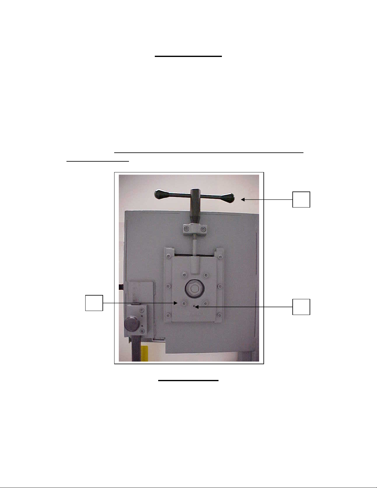
Adjustments
Blade Tension Handle (Item A) – Used to remove and install saw blade.
Also used to set the correct blade tension – Be sure blade is tight.
Upper Blade Wheel Cant Adjustment (Items B&C) – If your saw should
get out of adjustment and the blade runs off the wheel or runs back
against the lip, loosen the two bottom bolts on the wheel slide. Turn the
set screw in or out to make the blade run approximately 1/32” away from
the lip on the back of the wheel. Tighten the two wheel slide bolts.
IMPORTANT: If the blade is allowed to run against the lip on the wheel it
will wear the lip off.
A
B
C
Lubricating
Gear Box: Your 14-10 gearbox is filled at the factory. Check the fluid
level on arrival, and then check every six months thereafter. Use 90
weight gear lube to maintain fluid level at the fill / check pipe plug.
Model 14-10 4
Page 5

5/13/07
Blade Selection
For Operator convenience, a blade selector chart is located inside the saw
cover. It provides recommended blade speeds, required teeth per inch,
and minimum cutting radius for various blade widths. The following chart
can be used to select the blade needed:
Standard Tooth Applications
Thickness of Material Teeth per Inch
Up to 1/8” 18 Teeth
1/8” to 1/4" 14 Teeth
1/4" to 1/2" 10 Teeth
1/2" to 1” 8 Teeth
1” to 3” 6 –4 Teeth
3” to 6” 4-6 Teeth
6” and longer 3H
Note: 1) You must have at least 3 teeth into your work or blade damage will result.
2) For straight cuts, a 3/4" inch blade is best.
Blade Speed (feet per minute)
To change blade speeds, lift the motor and move the v-belt to one of the
three speeds offered: 70/140/270/540. Refer to the blade selector chart
inside the cover on your 14-10 for the appropriate speed.
Blade Removal and Installation
To remove the blade, release the blade tension handle. (Item A on page
4). Remove the blade.
To install the blade, place the blade over the bottom wheel, then on the
top wheel. Teeth must point down toward the table. Tighten the blade
tension handle enough to hold the blade firmly in place, and the push the
blade into the guide inserts. Turn the machine on to allow the blade to
position itself and then finish tightening the blade. IMPORTANT: Blade
must be tight to insure straight cut.
Please Note:
The most common causes for your 14-10 not cutting straight are:
1) Blade tension is too low.
2) The blade is either dull or worn on one side.
3) The blade is upside down. The teeth must point down toward
the table.
Model 14-10 5
Page 6
5/13/07
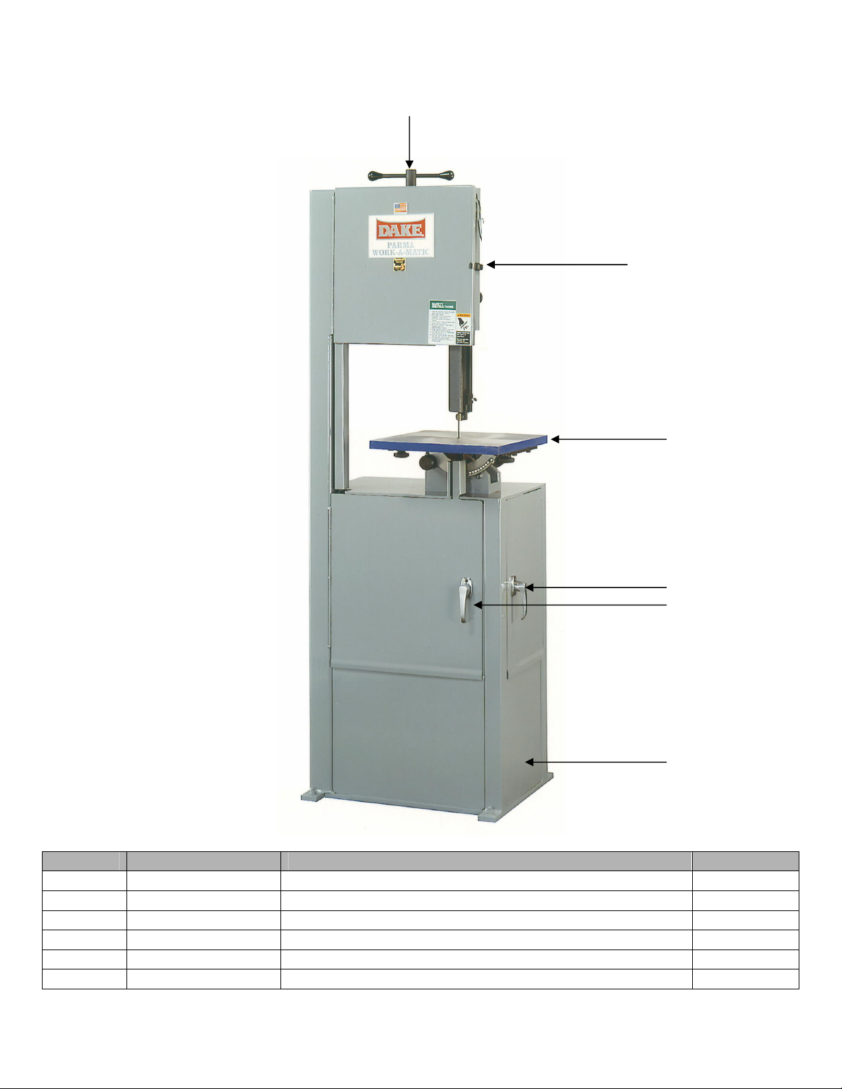
1
Item Part Number Description Quantity
1 716716 Tension Handle Assembly 1
2 86747 Door Latch 1
3 87088 Table 1
4a 300568 Door Handle 2
4b 300569 Door Latch 2
5 716745 Frame Assembly 1
2
3
4
5
Model 14-10 6
Page 7

5/13/07
4
Item Part Number Description Quantity
1 716716 Tension Handle Assembly 1
86828 Tension Handle Body 1
87104 Tension Handle 2
2 716705 Wheel Assembly 2
300459 Band, Blade Wheel 1
300466 Retaining Ring 2
300693 Bearing, Wheel 2
86795 Wheel Blade – Lower/Upper 1
86803 Axle Wheel Lower/Upper 1
86804 Stud – Wheel 1
3 300917 & 300918 Blade Guard 1
300342 Thumb Screws 2
4 300585 Speed Selector Label 1
1
2
3
2
Model 14-10 7
Page 8

5/13/07
1
2
10
11
12
13
3
4
5
6
7
8
9
Item Part Number Description Quantity
1 43450 Cap Screw 2
2 86827 Pillow Block 1
3 86830 Tension Screw 1
4 43447 Cap Screw 6
5a 86824 Wheel Slide – External piece 1
5b 86825 Wheel Slide Adjustment – Internal piece 1
6 86826 Rail Wheel Slide 2
7a 43922 Nut 1
7b 43638 Washer 1
8a 43452 Soc Cap Screw 3/8-16 x 1-3/4 4
8b 43632 Washer 5/16” flat 4
9 43591 Set Screw 3/8-16 x 1 1
10 86810 Guide Bar Holder 1
11 300832 Knob Assembly 1-1/2” 1
12 70287 Roll pin 2
13 43451 Cap Screw 2
Model 14-10 8
Page 9

5/13/07
2
4
6
11
14
13
5
4
3
12
1
7
9
8
10
Item Part Number Description Quantity
716749 Saddle Assembly - 1
1 87081 Table Top Base 1
2 87025 Table Lock 1
3 43939 Nut, Hex Jam, 7/16-20 1
4 44033 Pin, Dowel 4
5 87078 Rocker Rings 2
6 87077 Pointer, Rocker Ring 1
7 43449 Screw, Soc Set 4
8 43451 Screw, Soc Cap 2
9 300564 Cam Follower 1
10 43939 Nut, Hex Jam 7/16-20 1
11 43591 Pin, Spiral or Roll 2
12 86806 Insert, Contour Guide Insert 1
13 87034 Lower Guide Holder 1 x 1-5/8” x 1-9/16” 1
14 87033 Guide Bracket 4” x 4” x ¾” x 1” long 1
Model 14-10 9
Page 10

5/13/07
1
4
Item Part Number Description Quantity
1 87029 Guide Bar 1
2 86912 Upper guide stem 1
3 43545 Screw, Soc Cap 1-1/2-6 x 4 1/2 1
4 87028 Upper Guide Swivel 1
5 86808 Holder Contour Insert 1
6 86807A Insert Contour Guide ¼” Blade Carbide 1
6 86807B Insert Contour Guide ¼” Blade Brass 1
6 86806B Insert Contour Guide ½” Blade Brass 1
6 86806A Insert Contour Guide ½” Blade Carbide 1
7 87012 Blade Guard 1
8 43545 Screw, Soc Set #10-24 x ¼, Cup point 1
2
3
5
7
6
8
Model 14-10 10
Page 11

5/13/07
2
Item Part Number Description Quantity
1 300473 Pulley, Gearbox 1
77449 Key for Pulley 1
2 300522 V-Belt 1
3 86798 Motor mounting axle 1
43314 Screw, Hex cap 5/16-18 x 3/4 2
43632 Washer 5/16 inch flat 2
4 86800 Block, motor mounting 2
43450 Screw, Soc Cap 3/8-16 x 1-1/4 4
300597 Screw, Soc Set 1/4 – 20 x 1/4 2
5 300542 Pulley, Motor 1
77449 Key for Pulley 1
6 300485 Motor, Single Phase 1
300486 Motor, Three Phase 1
1
3
4
5
7
6
Model 14-10 11
Page 12

5/13/07
Model 14-10 12
Page 13

5/13/07
Item Part Number Description Quantity
716712 Gearbox Assembly 1
300472 Bearing, Seal 2
300490 Gasket, Gearbox 1
300491 Gasket, Gearbox 4
300589 Dowel Pin 3/16 x 1/2 2
43412 Screw, Soc Cap 16
43414 Screw, Soc Cap 6
43590 Screw, Soc Set 3
86820 Bearing Cover, Small/hole 2
86821 Bearing Cover, Small 2
86822 Gearbox Casting 1
86823 Cover, Gearbox 1
12 300666 Gear, Worm 40T Bronze 1
13 86784 80 Tooth Gear 1
14 300456 Worm, 4-Lead 1
15 300646 24 Tooth Gear 1
20 300454 Bearing, Gearbox 2
21 300448 Bearing, Gearbox 2
22 86785 Shaft, Main Drive 1
23 86781 Axle, Gearbox-Short 1
28 86783 Spacer, Gearbox 1-1/4 1
29 86786 Spacer, Gearbox 1
30 300449 Key, Woodruff #13 2
31 300451 Key, Woodruff #5 1
Electrical components
Description Part number
Contactor 460 volt 300715
contactor 230 volt 3 phase 300714
Contactor 220 volt 1 phase 300718
Contactor 110 volt 300717
Stop button 716539
Start button 716540
E-Stop button 716538
Model 14-10 13
Page 14

5/13/07
110 Volt Single Phase
Model 14-10 14
Page 15

220 Volt Single Phase
5/13/07
Model 14-10 15
Page 16

5/13/07
230 Volt Three Phase
Model 14-10 16
Page 17

460 Volt Three Phase
5/13/07
Model 14-10 17
 Loading...