

Page 1
INSTRUCTION MANUAL
MODEL SE-912
METAL CUTTING BANDSAW MACHINE
724 Robbins Road
Grand Haven, MI 49417
Phone: 616-842-7110, 800-937-3253
Fax: 616-842-0859, 800-846-3253
Web: www.dakecorp.com
E-mail: customerservice@dakecorp.com
technicalservice@dakecorp.com
- 1 -
Page 2

Table of Contents Page No
1 Warning ….………………………………………………………………..… 3
2 Safety rules for all tools...…………………………………………………… 3
3 Specification ………………………………………………………………… 7
4 Transportation of machine ………………………………………………..… 7
5 Installation …………………………………………………………………… 7
6 Minimum Room Space for Machine Operation …………………………… 8
7 Make proper tooth selection ……………………………………………….… 8
8 BI-Metal speeds and feeds. 10
9 Assembly ……………………………………………………………………. 12
10 Operation …………………………………………………………………. 13
11 Blade guide bearing adjustment …..……………………………………… 16
12 Blade track adjustment. 18
13 Maintenance …………………..………………………………………………. 18
14 Lubrication ……………………………………………………………………. 19
15 Trouble Shooting ……………………………………………………………... 20-21
16 Circuit Diagram ……………………….……………………………………… 22/24
17 Electrical Specification Chart ………..……………………………………….23/25
18 Parts Lists …………………………………………………………………… 26-32
- 2 -
Page 3
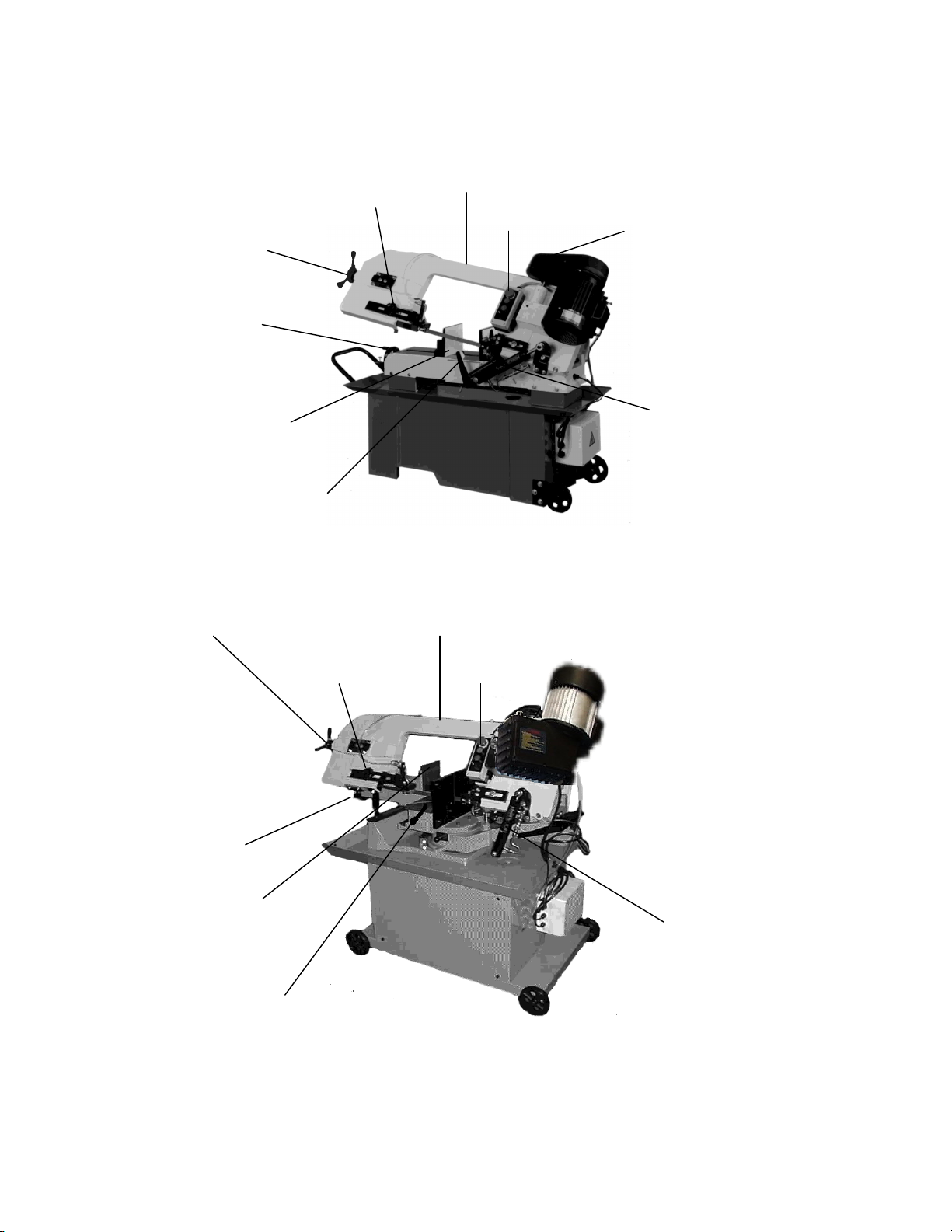
Guide adjustable knob
Blade adjustable knob
Hand vise wheel
Interlock switch
Switch
Motor pulley cover
Vise jaw bracket
Blade adjustable handle
Guide adjustable knob
Hand vise wheel
Cylinder
Stop block
Interlock switch
Gear box
Switch
Vise jaw bracket
Cylinder
Stop block
- 3 -
Page 4

WARNING: FAILURE TO FOLLOW THESE RULES
MAY RESULT IN SERIOUS PERSONAL INJURY
As with all machinery there are certain hazards involved with operation and use of the machine.
Using the machine with respect and caution will considerably lessen the possibility of personal
injury. However, if normal safety precautions are overlooked or ignored, personal injury to the
operator may result.
This machine was designed for certain applications only. We strongly recommend that this machine
NOT be modified and/or used for any application other than for which it was designed. If you have
any questions relative to its application DO NOT use the machine until you contact with us and we
have advised you.
Your machine might not come with a power socket or plug. Before using this machine, please
Do ask your local dealer to install the socket or plug on the power cable end.
SAFETY RULES FOR ALL TOOLS
A. USER:
(1). WEAR PROPER APPAREL. No loose clothing, gloves, rings, bracelets, or other jewelry to
get caught in moving parts.
Non-slip foot wear is recommended. Wear protective hair covering to contain long hair.
(2). ALWAYS WEAR EYE PROTECTION. Refer to ANSLZ87.1 standard for appropriate
recommendations.
Also use face or dust mask if cutting operation is dusty.
(3). DON'T OVERREACH. Keep proper footing and balance at all times.
(4). NEVER STAND ON TOOL. Serious injury could occur if the tool is tipped or if the cutting
tool is accidentally contacted.
(5). NEVER LEAVE TOOL RUNNING UNATTENDED. TURN POWER OFF. Don't leave
tool until it comes to a complete stop.
(6). DRUGS, ALCOHOL, MEDICATION. Do not operate tool while under the influence of
drug, alcohol or any medication.
(7). MAKE SURE TOOL IS DISCONNECTED FROM POWER SUPPLY. While motor is
being mounted, connected or reconnected.
(8). ALWAYS keep hands and fingers away from the blade.
(9). STOP the machine before removing chips.
(10). SHUT- OFF power and clean the BAND SAW and work area before leaving the machine.
B. USE OF MACHINE:
(1). REMOVE ADJUSTING KEYS AND WRENCHES. Form habit of checking to see that
- 4 -
Page 5

keys and adjusting wrenches are removed from tool before turning it "on".
(2). DON'T FORCE TOOL. It will do the job better and be safer at the rate for which it was
designed.
(3). USE RIGHT TOOL. Don't force tool or attachment to do a job for which it was not
designed.
(4). SECURE WORK. Use clamps or a vise to hold work when practical. It's safer than using
your hand frees both hands to operate tool.
(5). MAINTAIN TOOLS IN TOP CONDITION. Keep tools sharp and clean for best and safest
performance. Follow instructions for lubricating and changing accessories.
(6). USE RECOMMENDED ACCESSORIES. Consult the owner's manual for recommended
accessories. The use of improper accessories may cause hazards.
(7). AVOID ACCIDENTAL STARTING. Make sure switch is in “OFF” position before
plugging in power cord.
(8). DIRECTIONOF FEED. Feed work into a blade or cutter against the direction of rotation of
the blade or cutter only.
(9). ADJUST AND POSITION the blade guide arm before starting the cut.
(10). KEEP BLADE GUIDE ARM TIGHT, A loose blade guide arm will affect sawing
accuracy.
(11). MAKE SURE blade speed is set correctly for material being cut.
(12). CHECK for proper blade size and type.
(13). STOP the machine before putting material in the vise.
(14). ALWAYS have stock firmly clamped in vise before starting cut.
(15). GROUNDALL TOOLS. If tool is equipped with three-prong plug, it should be plugged
into a three-hole electrical receptacle. If an adapter is used to accommodate a twoprong receptacle,
the adapter lug must be attached to a known ground. Never remove the third prong.
C. ADJUSTMENT:
MAKE all adjustments with the power off. In order to obtain the machine. Precision and correct
ways of adjustment while assembling, the user should read the detailed instruction in this manual.
D. WORKING ENVIRONMENT:
(1). KEEP WORK AREA CLEAN. Cluttered areas and benches invite accidents.
(2). DON'T USE IN DANGEROUS ENVIRONMENT. Don't use power tools in damp or wet
locations, or expose them to rain. Keep work area well-lighted.
(3). KEEP CHILEREN AND VISITIORS AWAY. All children and visitors should be kept a
safe distance from work area.
(4). DON’T install & use this machine in explosive, dangerous environment.
- 5 -
Page 6

E. MAINTENANCE:
(1). DISCONNECT machine from power source when making repairs.
(2). CHECK DAMAGED PARTS. Before further use of the tool, a guard or other part that is
damaged should be carefully checked to ensure that it will operate properly and perform its
intended function check for alignment of moving parts, binding of moving parts, breakage of parts,
mounting, and any other conditions that may affect its operation. A guard or other part that is
damaged should be properly repaired or replaced.
(3). DISCONNECT TOOLS before servicing and when changing accessories such as blades, bits,
cutters, etc.
(4). MAKE SURE that blade tension and blade tacking are properly adjusted.
(5). RE-CHECK blade tension after initial cut with a new blade.
(6). TO RPOLONG BLADE LIFE ALWAYS release blade tension at the end of each work day.
(7).CHECK COOLANT DAILY Low coolant level can cause foaming and high blade
temperatures. Dirty or week coolant can clog pump, cause crooked. Cause, low cutting rate and
permanent blade failure. Dirty coolant can cause the growth of bacteria with ensuing skin
irritation.
(8). WHEN CUTTING MAGNESIUM NEVER use soluble oils or emulsions (oil-water mix) as
water will greatly intensify any accidental magnesium chip fire. See your industrial coolant
supplier for specific coolant recommendations when cutting magnesium.
(9). TO PRNMT corrosion of machined surfaces when a soluble on is used as coolant, pay
particular attention to wiping dry the surfaces where fluid accumulates and does not evaporate
quickly, such as between the machine bed and vise.
F. SPECTIFIED USAGE:
This machine is used only for general metals cutting within the range of cutting capacity.
G. NOISE:
A weighted sound pressure level: under 80 dB.
H. SAFETY DEVICE:
By the time the saw arm cover is opened, the interlock switch will function to stop the
Machine. Do not remove this switch from machine for any reason, and check its function
frequently.
- 6 -
Page 7
1.SPECIFICATION
MOTOR
3∮O.75KW(1HP) 1∮1.1KW(1-1/2HP)
Saw Blade Speed
(FPM)
912G.912GDR
912B.912DR 60Hz
60Hz
158 213 308 50Hz 130 177 255
98 164 246 328 50Hz 81 135 203 270
Blade Size 19.05x0.8x2655 ( Carbon Blade )
Dimension LxWxH (mm)
1325x630x1050(G) 1380x460x1050(B) 1350x650x1100(DR.GDR)
N.W / G.W (kgs) 155 / 180(G.DR.GDR) 140/165(B)
Working Capacity
Packing Measurement (mm) LxWxH
0°
○(mm)
□(mm)
○(mm)
±45°
□(mm)
1420x690x1100(G) 1420x530x1100(B) 1450x740x1140(DR.GDR)
178x305(7”x12”)(G.B) 127x300(5”x12”)(DR.GDR)
150(6”)(G.B) 165(6-1/2”)(DR.GDR)
127x150(5”x6”)(G.B) 100x200(4’x8’)(DR.GDR)
230(9”)
Overall height (w/o stand) 1600mm(63")
Noise 80 dB MAX
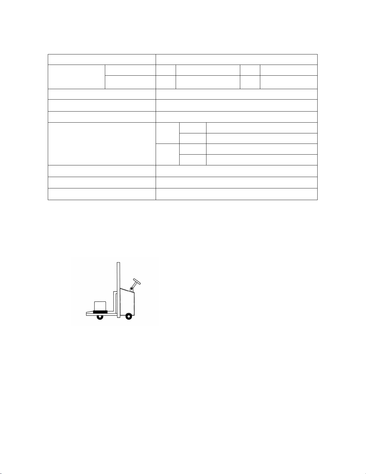
2.TRANSPORTATION OF MACHINE:
Unpacking
1. Transportation to desired location before unpacking, please use lifting jack.(Fig. B)
2. Transportation after unpacking, please use heavy duty fiber belt to lift up the machine.
Fig. B
ALLWAYS KEEP PROPER FOOTING & BALANCE WHILE MOVING THIS MACHINE.
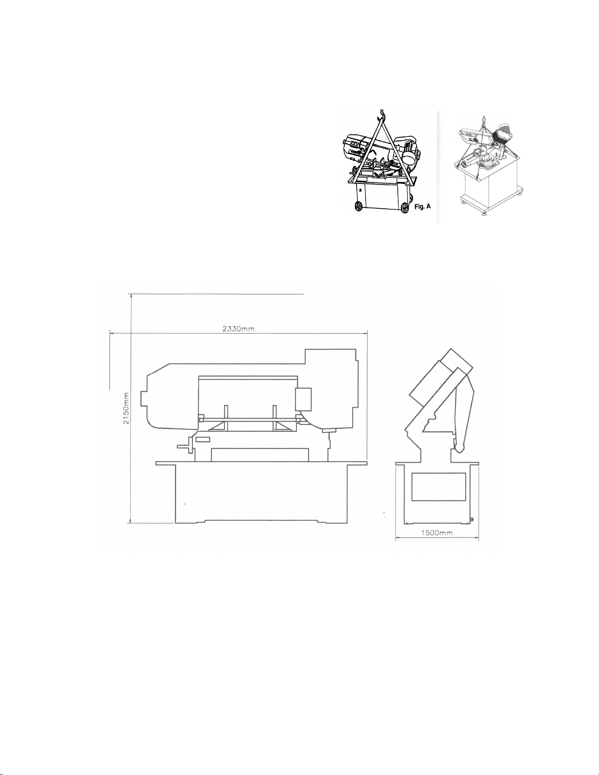
Installation:
This machine weighs 155 kg. It is recommended that the machine shall be transported, with help
of lifting jack.
Transportation Recommendation:
(1). Tighten all locks before operation.
(2). ALWAYS Keep proper footing & balance while moving this 155kgs machine, and only use
heavy duty fiber belt to lift the machine as Fig. A
- 7 -
Page 8
(3). TURN OFF the power before wiring, & be sure
machine in proper grounding, Overload & circuit
breaker is recommended for safety wiring.
(4). CHECK carefully if the saw blade is running in
Counter-clockwise direction, if not reverse the
Wiring per circuit diagram then repeat the running
Test.
(5). KEEP machine always out from sun, dust, wet,
raining area.
912(B.G) 912(DR.GDR)
3. MINIMUM ROOM SPACE FOR MACHINE OPERATION
4. MAKE PROPER TOOTH SELECTION
For maximum cutting efficiency and lowest cost per cut, it is important to select the blade with
the right number of teeth per inch (TPI) for the material being cut. The material size and shape
dictate tooth selection.
- 8 -
Page 9

TOOTH
SELECTION
You need to consider:
1. The width of the cut. That is, the distance in the cut that each tooth must travel from the point it
Enters the work piece until it leaves the work piece, and
2.The shape of the work piece.
Squares, Rectangles, Flats (Symbol : ■)
Locate the width of cut on the chart. (Inches on the outer circle and millimeters on the
inner circle.) Select the tooth pitch on the ring marked with the square shape which aligns
with the width of cut.
EXAMPLE: 6" (150mm) square, use a 2/3 Vari-Tooth.
Round Solids (Symbol : ●)
Locate the diameter of your work piece on the chart. Select the tooth pitch on the ring
marked with the round shape which aligns with the size of stock you are cutting.
EXAMPLE: 4" (100mm) round, use a 3/4 Vari-Tooth.
Tubing, Pipe, Structurals( Symbol : O H ^ )
Determine the average width of cut by dividing the area of the work piece by the distance
the saw blade must travel to finish the cut. Locate the average width of cut on the chart.
Select the tooth Ditch on the ring marked with the tubing and structural shape which
aligns with the average width you are cutting.
EXAMPLE: 4"(100mm) outside diameter, 3"(75mm) inside diameter tubing.
4"(100mm) OD =12.5 sq.ln. (79cm2)
3"(75 mm) ID = 7.0 sq.ln. (44cm2)
Area = 5.5 sq.ln. (35cm2)
5.5 sq.ln. (35cm2) / 4" (100mm) distance =1.38(35mm) average width
1.38" (35mm), use a 4/6 Vari-Tooth
NOTE: The band speed and cutting rate recommendations presented on this chart are
approximations and are to be used as a starting point for most applications. For exact
sawing parameters' consult your saw blade supplier.
- 9 -
Page 10

FT./MIN
M/MIN
330,365
284 87
1751,182,220,510
234 71
630 229 70 811 214 65
1117
339 103
1141,1144
279 85
1030
329 100 1008,1015,1020,1025
319 97 1035
309 94 1018,1021,1022
299 91
A36(SHAPES),1040
269 82
1044,1045
219 67
1095
184 56
8615,8620,8622
239 73
5. BI-METAL SPEEDS AND FEEDS
These figures are a guide to cutting 4"(100mm) material (with a 314 Vari-Tooth) when using a
cutting fluid.
Increase Band Speed: 15% When cutting 1/4"(6.4mm) material (l0/l4 Vari-Tooth)
12% When cutting 3/4"(19 mm) material (6/10 Vari-Tooth)
10% When cutting 1-1/4"(32 mm) material (5/8 Vari-Tooth)
5% When cutting 2-1/2" (64 mm) material (4/6 Vari-Tooth)
Decrease Band Speed: 12% When cutting 8"(200mm) material (2/3 Vari-Tooth)
MATERIAL ALLOY
ASTM NO.
Copper
173,932 314 96
Alloy
623,624 264 81
230,260,272 244 74
280,264,632,655 244 74
101,102,110,122,172 234 71
625,706,715,934 234 71
Carbon
Steel
1137 289 88
1141 HI STRESS 279 85
BAND SPEED
Ni-Cr-Mo
Alloy Steel
1026,1513 299 91
1042,1541 249 76
1060 199 61
4340,E4340,8630 219 67
- 10 -
Page 11
Ni-Cr-Mo
8640,
199 61
A-2 179 55
D-2 90 27 H-11,H
-
12,H
-13
189 58
420 189 58
410,502
140 43
431 95 29
304,324
120 36 304L
115 35 347 110 33 316,316L
100 30
Alloy Steel
E9310 174 53
Tool Steel
A-6 199 61
A-10 159 49
Stainless
Steel
430 149 46
414 115 35
440C 80 24
416 189 58
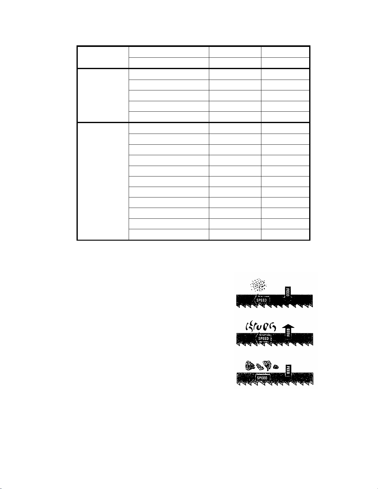
TELLTALE CHIPS
Chips are the best indicator of correct feed force. Monitor chip information and adjust feed
accordingly.
Thin or powdered chips – increase feed rate or reduce band
speed.
Burned heavy chips – reduce feed rate and/or band speed.
Curly silvery and warm chips – optimum feed rate and band
speed.
- 11 -
Page 12

6. ASSEMBLY
A 1 HP, motor, split phase or capacitor-start it recommended for best economical performance.
Counterclockwise rotation is required. Note that rotation can be reversed by allowing directions
Given on terminal or nameplate.
(1). Assemble the motor Mounting plate to the head using the long bolt Note that the flat side of
the plate faces up.
(2). Assemble the guard plate to the head using the screw and Lock Washer and the Carriage Bolt
Washer and Wing Nut are used to secure the motor mounting plate to the Guard plate through the
slotted hole in the Guard plate. These components also serve to position and lock the motor in
place for proper speed/ belt adjustment.
(3). Place the spacer over the long Bolt and secure it wit the nut.
(4). Secure the Motor to the Motor Mounting plate with the four bolts and nuts. Note; the motor
shaft is placed through the large opening in the Guard plate and must be parallel with the drive
Shaft.
(5). Assemble the Motor Pulley, the smaller of the two provided, to the motor shaft Note, the
larger diameter must be closest to the motor.
Do not tighten the set screw.
(6). Assemble the Driven Pulley, the larger of the two provided, to the protruding drive Shaft Note
the small diameter must be closest to the bearing.
Do not tighten the set screw.
(7).Place the belt into one of the pulley grooves and the other end into the respective grooves of
the second pulley.
(8) Line up the belt and both pulleys such that the belt is running parallel in the pulley grooves.
(9).Tighten the set screws of both pulleys in this position.
(10). Place the belt into proper pulley combination for proper blade speed. See material cutting
Chart.
(11). Adjust the position of the Motor to obtain approximately 1/2" depression in the belt when
applying pressure with your thumb.
(12). Tighten the head screw Holding the Motor Mounting plate to the Guard plate.
(13). Connect the Electrical Harness to the motor terminal box. The motor should be protected
with a time delay fuse or circuit breaker with rated amperage slightly greater than the full load
amperage of the motor.
- 12 -
Page 13

Soft Brass
Aluminum Plastic
308 255 328 270 Largest
Small
7. OPERATION
WORK SET UP
(1). Raise the saw head to the highest position.
(2). Open vise to accept the Piece to be cut by rotating the wheel at the end the base.
(3). Place work piece on saw bed. If the piece is long, support the end.
(4). Clamp work pieced securely in vise.
WORK STOP ADJUSTMENT
(1). Loosen the thumb screw holding the work stop casting to the shaft.
(2). Adjust the work stop casting to the desired length position.
(3). Rotate the work stop to as close to the bottom of the cut as possible.
(4). Tighten thumbscrew.
(5). DO NOT ALLOW the blade to rest on the work while the motor is shut off.
BLADE SPEEDS
When using your Band saw always change the blade speed to best suit the material being cut
the material Cutting Shirt givers suggested settings for several materials.
Speed F.P.M Belt Groove Used
912(G.GDR) 912(B.DR)
Material
Motor
60Hz 50Hz 60Hz 50Hz
Pulley
Tool, Stainless
Alloy Steels
158 130 98 81 Small Largest
Bearing Bronze
Medium to High
Carbon Steels
164 135 Medium Large
Hard Brass or Bronze
213 177
Low to Medium
Carbon Steel
246 203 Large Medium
MANUAL OF GEAR TYPE SPEED CHANGING
(1) Select the proper cutting speed according to the material of work-pieces
And blade select chart.
(2) Turn the speed-changing handle directly for the necessary speed.
Saw
Pulley
(3) Changing speed during cutting is prohibited.
(4) But changing speed when machine is stopped and running (before cutting)
Is available.
- 13 -
Page 14

BLADE DIRECTION OF TRAVEL
Be sure the Made is assembled to the pulleys such that the vertical edge engages the work
piece first.
BLADE MOVEMENT
Blade Direction
STARTING SAW
Switch button function description
(Emergency Push Button)
(Start Button)
(Stop Button)
(Coolant Selection Switch)
CAUIION: NEVER OPERATE SAW WITHOUT BLADE GUARDS IN PLACE.
Be sure the blade is not in contact with the work when the motor is started. Start the motor, allow
the saw to come to full speed, and then begin the cut by letting the head down slowly onto the work.
DO NOT DROP OR FORCE. Let the weight of the saw head provide the cutting force. The saw
automatically shuts off at the end of the cut.
BLADE SELECTION
An 8-tooth per inch, general-use blade is furnished with this metal Cutting Band Saw. Additional
blades in 4, 6, 8, and 10 tooth sizes are available. The choice of blade pitch is governed by the
thinness of the work to be cut: the thinner the work piece, the more teeth advised. A minimum of
three (3) teeth should engage the work piece at all times for proper cutting if the teeth of the Blade
- 14 -
Page 15

are so far apart that they straddle the work, severe damage to the work piece and to the Made can
result.
CHANGING BLADE
Raise saw head to the highest position and open the blade guards. Loosen tension screw knob
sufficiently to allow the saw blade to slip off the wheels. Install the new blade with teeth slanting
toward the motor as follows:
(1). Place the blade in between each of the guide bearings.
(2). Slip the blade around the motor pulley (bottom) with the left hand and hold in position.
(3). Hold the blade taut against the motor pulley by pulling the blade upward with the right hand
Which is placed at the top of the Made?
(4). Remove left hand from. Bottom pulley and place is at the top aide of the Made to continue the
Application on the upward pull on the blade.
(5). Remove right hand from blade and adjust the position of the top pulley to permit left hand to
slip the blade around the pulley using the thumb, index and little finger as guides.
(6). Adjust the blade tension knob clockwise until it is just right enough so no blade slippage
occurs. Do not tighten excessively.
(7). Replace the blade guards.
(8). Place 2-3 drops of oil on the blade.
USAGE OF THE OUICK VISE
The work piece is placed between the vise
jaws with the amount to be cut-off
extending out past the blade. Your
machine is equipped with a "quick action"
vise jaw which allows you to instantly
position the moveable vise jaw (B).
Simply turn Handwheel (A)
counterclockwise 1/2 turn and move the
vise jaw (B) to the desired position. Then
tighten the vise jaw (B) against the
work-piece by turning hand-wheel clockwise.
QUICK VISE ADJUSTMENT FOR ANGLE CUT (912B.912G)
(1). Loosen the A. B. C. D. Screw.
(2). Adjust rear vise to the threaded hole position. (E)
(3). Set the scale to the desired angle.
(4). Adjust the front vise (F) to parallel the rear vise (E)
(5). Tighten the A. B. C. D. Screw.
- 15 -
Page 16

QUICK VISE ADJUSTMENT FOR ANGLE CUT (912DR.912GDR)
(1). Pull out plastic knob (A).turn and lock the plastic knob.
(2). Loosen grip (B).Then rotates the Body Frame for the desired angle. Be aware the blade
Position is higher than the Vise Table by pulling up the Body Frame when
counter-clockwise
Rotation for miter cutting. And for clockwise rotation for angle cutting higher the Body
Frame and keep the blade position higher than the vise. Then pull forward the vise Jaw
Bracket (Front) to a proper location.
(4). Fasten the grip (B) when the cutting angle is reached.
(5). There is angle set-screw for ±45°rotation
A
B
8. BLADE GUIDE BEARING ADJUSTMENT
ATTENTION: This is the most important adjustment on your saw. It is impossible to get
satisfactory work from your saw if the blade guides are not properly adjusted. The blade guide
bearings on your metal. Cutting Band Saw are adjusted and power tested with several test cuts
before leaving the factory to insure proper setting The need for adjustment should rarely occur
when the saw is used properly. If the guides do get out of adjustment though, it is extremely
important to readjust immediately. If improper adjustment in maintained, the blade will not cut
straight, and if the situation is not corrected it will cause serious blade damage. Because guide
adjustment is a critical factor in the performance of your saw, it is always best to try a new blade to
see if this will correct poor cutting before beginning to adjust. If a blade becomes dull on one side
sooner than the other, for example, it will begin cutting crooked. A blade change will correct this
problem the guide adjustment will not. If a new blade does not correct the problem, check the blade
- 16 -
Page 17

guides for proper spacing.
NOTE: There should be from 000 (just touching) 001 clearance between the blade and guide
bearings to obtain this clearance adjust as follows:
1. The inner guide bearing is fixed and cannot be adjusted.
2. The outer guide bearing is mounted to an eccentric bushing and can be adjusted.
3. Loosen the nut while holding the bolt with an Alien wrench.
4. Position the eccentric by turning the bolt to the desired position of clearance.
5. Tighten the nut.
6. Adjust the second blade guide bearing in the same manner.
REMARK:
1. Adjust the tension of blade until the back of the blade (A) against the blade wheel (front)
lightly.
2. Be sure the nut (E) is tightened.
3. Turn the eccentric shaft (B) counterclockwise, when the bearing (D) touches the saw blade
properly; tighten the nut (E).
4. To adjust, loosen set screw(F) and move the blade adjustable up or down until it lightly
Touches the back of the blade (A).
5. The carbide blade guides(L)Fig.1,should also be adjusted so they lightly touch the blade
by loosening screws (M).
6. Repeat 1. 2, 3, 4and 5 steps to adjust the other side's blade guide bearings (G).
7. Correct the base and blade to be a vertical position with a scale. If necessary, loosen set
screw (F).
8. Set down the blade frame, correct the jaw vise (H) and blade to be a vertical position with a
Scale then tighten the set screws (I).
9. Loosen set screw (K), move front jaw vise (J) to against rear jaw vise (H) tightly. Finish
Correcting by tightening set screw (K)
M
A
G
Fig.1 Fig.2
C
D
L
- 17 -
Page 18

9. BLADE TRACK ADJUSTMENT
(1). Open the blade guard.
(2). Remove the blade guide assemblies (top and bottom)
(3). Loosen the hex head screw in the tilting mechanism to a point where it is loose but snug.
(4). with the machine running, adjust both the set crew and blade tension knob simultaneously to
keep constant tension on the blade. The set screw and blade tension knob are always turned in
opposite directions, i.e., when one is turned clockwise the other is turned counterclockwise.
The blade is tracking properly when the back side just touches the shoulder of pulley or a
slight gap appears near the center line of the pulley. Care should be taken not to over-tighten
the saw blade since this will give a false adjustment and limit life of the blade.
(5). Tighten the hex head screw in tilting mechanism. IMPORTANT: Sometimes in trying to
make this critical adjustment it is possible to cause the basic setting to be misaligned. Should
this occur, proceed as follows:
a. Loosen the set screw and back it out as far as it can go and still remain in the threaded hole.
b. Turn the hex head screw clockwise until it stops (do not tighten).
c. Turn the set screw clockwise until it bottoms, then continue for half a turn and check the
tracking by turning on the machine.
d. If further adjustment is required, go back to step 4.
(6). Turn off power to the machine.
(7). Replace the clad guide assemblies--it may be necessary to loosen the blade tension lightly.
(8). Adjust the vertical position of blade guide bearing assemblies so that the back side of the
blade just touches the ball bearing.
(9). Make a final run to check tracking. It required, touch up adjustment (See stop 4)
(10). Replace the blade guards.
Hydraulic Feed Adjustment
(1) To adjust the feeding rate when in cutting, turn the volume valve (A) clockwise for faster
feeding, counterclockwise for slower feeding.
(2) When cutting feed is too fast, raise the saw arm, then slower the feed rate to prevent blade
damage.
10. MAINTENANCE
CAUTION: MAKE CERTAIN THAT THE UNIT IS DISCONNECTED FROM THE POWER
SOURCE BEFORE ATTEMPTING TO SE RV ICE OR REMOVE ANY COMPONENT.
That's easier to keep machine in good condition or best performance by means of maintaining it at
any time than remedy it after it is out of order.
- 18 -
Page 19

(1) Daily Maintenance (by operator)
(a) Fill the lubricant before starting machine everyday.
(b) If the temperature of spindle caused over-heating or strange noise, stop machine immediately
to cheek it for keeping accurate performance.
(c) Keep work area clean; release vise, cutter, work-piece from table; switch off power source;
take chip or dust away from machine and follow instructions lubrication or coating rust proof
oil before leaving.
(2) Weekly Maintenance
(a) Clean and coat the leading screw with oil.
(b) Check to see if sliding surface and turning parts lack of lubricant. If the lubricant is
insufficient, fill it.
(3) Monthly Maintenance
(a) Check if the fixed portion llave been loose.
(b) Lubricate bearing, worm, and worm shaft to avoid the wearing.
(4) Yearly Maintenance
(a) Adjust table to horizontal position for maintenance of accuracy.
(b) Check electric cord, plugs, switches at least once a year to avoid loosening or wearing.
LUBRICATION
Lubricate the following components using SAE-30 oil as noted.
(1). Ball-bearing none.
(2). Driven pulley bearing 6-8 drops a week.
(3). Vise lead screw as needed.
(4). the drive gears run in an oil bath and will not require a lubricant change more often than once
a year, unless the lubricant is accidentally contaminated or a leak occurs because of improper
Replacement of the gear box covers. During the first few days of operation, the worm gear drive
will run hot. Unless the temperature exceeds 200F. there is no cause for alarm.
The following lubricants may be used for- the gear box:
Atlantic Refinery Co. Mogul Cyl. Oil
Cities Service Gptimus No. 6
Gulf Refinery Co Medium Gear Oil
- 19 -
Page 20

11. TROUBLE SHOOTING
Symptom
skill.
loose
Blade
.
2. T
oo heavy pressure; too
slow
2. Decrease pressure
, increase
Possible Cause(s) Corrective Action
Excessive Blade
Breakage
1. Materials loosen in vise.
2. Incorrect speed or feed
3.Blade teeth spacing too large
4. Material too coarse
5. Incorrect blade tension
6.Teeth in contact with material
before saw is started
7. Blade rubs on wheel flange
8. Miss-aligned guide bearings
9. Blade too thick
10 Cracking at weld
Premature Blade Dulling 1. Teeth too coarse
2. Too much speed
3. Inadequate feed pressure
1. Clamp work securely
2. Adjust speed or feed
3. Replace with a small teeth
spacing blade
4. Use a blade of slow speed
and small teeth spacing
5. Adjust to where blade just
does not slip on wheel
6. Place blade in contact
with work after motor is
starred
7. Adjust wheel alignment
8. Adjust guide bearings
9. Use thinner blade
10. Weld again, note the weld
1. Use finer teeth
2. Decrease speed
3. Decrease spring tension on
Unusual Wear on
Side/Back of Blade
Teeth Ripping from
4.Hard spots or scale on material
5. Work hardening of material.
6.Blade twist
7. Insufficient blade
8. Blade slide
1.Blade guides worn.
2.Blade guide bearings not adjust
properly
3.Blade guide bearing bracket is
1. Tooth too coarse for work
side of saw
4. Reduce speed, increase feed
pressure
5. Increase feed pressure by
reducing spring tension
6. Replace with a new blade,
and adjust blade tension
7. Tighten blade tension
adjustable knob
8. Tighten blade tension
1.Replace.
2.Adjust as per operators
manual
3.Tighten.
1. Use finer tooth blade.
- 20 -
Page 21

wheel flanges
operating instructio
ns.
3. Blade tension loose
3. Adjust blade tension
.
speed.
3. Vibrating work-piece.
4. Gullets loading
Motor running too hot 1. Blade tension too high.
2. Drive belt tension too high.
3. Blade is too coarse for work
4. Blade is too fine for work
5. Gears aligned improperly
6. Gears need lubrication
7. Cut is binding blade
Bad Cuts (Crooked) 1. Feed pressure too great.
2. Guide bearings not adjusted
properly
speed
3. Clamp work piece securely
4. Use coarser tooth blade or
brush to remove chips.
1. Reduce tension on blade.
2. Reduce tension on drive belt.
3. Use finer blade.
4. Use coarse blade.
5. Adjust gears so that worm is
in center of gear.
6. Check oil path.
7. Decrease reed anti speed
1. Reduce pressure by
increasing spring tension on
side of saw
2. Adjust guide bearing, the
clearance can not greater
than 0.001.
Bad Cuts (Rough)
Blade is twisting
3. Inadequate blade tension.
4. Dull blade.
5. Speed incorrect.
6. Blade guides spaced out too much
7. Blade guide assembly loose
8. Blade truck too far away from
1. Too much speed or feed
2. Blade is too coarse
1. Cut is binding blade.
2. Too much blade tension.
3. Increase blade tension by
adjust blade tension
4. Replace blade
5. Adjust speed
6. Adjust guides space.
7. Tighten
8. Re-track blade according to
1. Decrease speed or feed.
2. Replace with finer blade.
1. Decrease reed pressure.
2. Decrease blade tension.
- 21 -
Page 22

ELECTRICAL SPECIFICATION
Green start
Part
Part name
Coolant switch 716558
button 716540
Red stop button 716539
E-stop button 716538
number
- 22 -
Page 23

ELECTRICAL SPECIFICATION
Part number Part name Qty Part number
Electrical box
301461
301462 Contactor 24volt 1 716540 Green start button 1
301795 Overload 1 716539 Red stop button 1
300828 Relay orange 1 7165387 E-stop button 1
302409 Motor reset button 1 300733
73326011 Transformer 1
complete 1 716558 Coolant on/off button 1
- 23 -
Part name Qty.
Limit switch end of
cut 1
Page 24

- 24 -
Page 25

- 25 -
Page 26

- 26 -
Page 27

MODEL SE 912B (After S/N 172344 or 02/2001)
ITEM DAKE NO. REF NO. DESCRIPTION SPECIFICATION
1 301266 192012A Swivel Base
2 301267 192009A Acme Screw or 300756
3 300906 K03 Key
4 300907 W002 Washer
5 300908 S607 Hex. Socket Headless
6 300751 191202 Wheel
7 300752 3027-1 Handle Knob
9 301268 181138B Acme Nut
10 300755 181604 Acme Nut
11 300989 181605 Button
12 300910 W203 Spring Washer
13 300911 191206 Retainer
14 78833 S721 Cross Round Head Srew
15 301269 181266 Fixed Bolt
16 301270 W008 Spring Washer 3/8"x25xt2
17 301271 192015 Vise Jaw Bracket(Front)
18 43331 S410 Hex. Socket Head Screw 3/8"x1-1/2"L
19 43916 N001 Hex. Nut 1/2"
20 300907 W002 Spring Washer 1/2"x28xt2
21 S501 Carriage Screw 1/2"x2"L
22 S003 Hex. Head Screw 1/2"x2"L
24 301288 192008 Vise Jaw Bracket(Rear)
25 43881 S708 Cross Round Head Screw 3/16"x3/8"L
26 W007 Spring Washer 3/16"x12xt0.8
27 301289 192044 Scale
28 301290 181117-1 Spring or 300943
29 301291 181118 Spring Adjusting Screw
30 301292 192040 Spring Handle Bracket
31 W016 Spring Washer 5/16"x23xt2
32 S022 Hex. Head Screw 5/16"x3/4"L
33 W014 Spring Washer 3/8"x23xt2
34 N005 Hex. Nut 3/8"
- 27 -
Page 28

Cylinder Complete Set
or
MODEL SE 912B (After S/N 172344 or 02/2001)
ITEM DAKE NO. REF. NO. DESCRIPTION SPECIFICATION
35 301293 192051 Bushing
36 301294 192042A Support Rod 36
37 S022 Hex. Head Screw 5/16"x3/4"L
38 301295 192003 Pivot Bracket
39 301296 181270 Washer
40 S012 Hex. Head Screw 3/8"x1-1/2"L
41 301297 ET2108 Wire Nipple 5/8"
42 301298 192033 Cylinder Protector
43 W018 Spring Washer 5/16"x23xt3
44 S022 Hex. Head Screw 5/16"x3/4"L
45 301299 181301-2 Cylinder Lower Support
46 W016 Spring Washer 5/16"x19xt1.5
47 S018 Hex. Head Screw 5/16"x1/2"L
48 301688 191224 Thumb Screw
49 S022 Hex. Head Screw 5/16"x3/4"L
50 301300 3021 Stock Stop Rod
51 300945 181125 Distance Set Bracket
52 300733 ET1624 Limit Switch
53 181431 Gear Box Gasket
54 301690 181420 Cover
55 43881 S708 Cross Round Head Screw 3/16"x3/8"L
56 192011 Fixed Plate
57 W005 Spring Washer 1/4"x16xt1.5
58 S019 Hex. Head Screw 5/16"x1-1/2"L
59 S014 Hex. Head Screw 3/8"x1-3/4"L
60 181112A Support Plate
61 S022 Hex. Head Screw 5/16"x3/4"L
62 W017 Spring Washer 5/16"x18xt1.5
63 N005 Hex. Nut 3/8"
64 300730 181304-2
65 S412 Hex. Socket Head Screw 3/8"x2-1/4"L
66 W013 Spring Washer 3/8"x20xt2
300750
- 28 -
RF-712N
Page 29

MODEL SE 912B (After S/N 172344 or 02/2001)
ITEM DAKE NO. REF. NO. DESCRIPTION SPECIFICATION
67 301191 181302-2 Cylinder Upper Support
69 N005 Hex. Nut 3/8"
70 S017 Hex. Head Screw 5/16"x1"L
72 192045S Stand Complete Assembly
73 S017 Hex. Head Screw 5/16"x1"L
74 W017 Spring Washer 5/16"x18xt1.5
75 N007 Hex. Nut 5/16"
76 S013 Hex. Head Screw 3/8"x1-1/4"L
77 N005 Hex. Nut 3/8"
78 301404 191106A Filter
79 S708 Cross Round Head Screw 3/16"x3/8"L
80 301284 ET1401 Toggle Switch
81 301285 3131 Switch Cover
82 301286 181932 Toggle Switch Cover
84 192019 Wheel Setting Bracket
85 W019 Spring Washer 5/8”x40xt3
86 S016 Hex. Head Screw 3/8”x3/4”L
87 192022 Wheel Rod
88 P202 Cotter Pin
89 300742 181129 Wheel
90 N007 Hex. Nut 5/16”
91 W015 Spring Washer 5/16”x12xt2
92 S022 Hex. Head Screw 5/16”x3/4”L
93 300953 192039 Knob W/Shaft
94 N005 Hex. Nut 3/8”
95 W014 Spring Washer 3/8”x23xt2
96 S013 Hex. Head Screw 3/8”x1-1/4”L
97 300962 181256 Coolant Tank
∮3x25L
97-1 300961 Filter
98 300754 MB13103 Pump 1/8HP/ 110/220V/60HZ/1PH
99 W004 Spring Washer 1/4"x19xt1.5
100 S701 Cross Round Head Screw 1/4"x1/2"L
- 29 -
Page 30

MODEL SE 912B (After S/N 172344 or 02/2001)
ITEM DAKE NO. REF. NO. DESCRIPTION SPECIFICATION
101 301454 181854 Hose OD16mmxID13mmx260m
102 301694 181852 Coupler 3/8"PT
103 301456 Hose
105 43881 S708 Cross Round Head Screw 3/16"x3/8"L
106 301455 181856 Valve 1/8” NTP
109 300343 181401 Electrical Box
110 43881 S708 Cross Round Head Screw 3/16"x3/8"L
111 ET2107 Wire Nipple 1/2"
112 181402 Cover
190 101073 3 Way Valve
191 1341089 Hose Fitting 1/4PTx1/4"
192 192056 Hose OD8xID6x1100L
193 S475 Hex. Socket Head Screw 1/4"x1-1/4"L
194 192053 Valve 1/4"PTx5/16"
195 192058 Hose OD12xID8x14000L
196 192057 Hose OD8xID6x400L
197 101079 Hose Bib
200 301172 192001 Body Frame
201 W204 Spring Washer 3/8"
202 S013 Hex. Head Screw 3/8"x1-1/4"L
203 192041 Support Plate
204 W005 Spring Washer 1/4"x16xt1.5
205 S201 Cross Round Head Screw 1/4"x1/2"L
206 S608 Hex. Socket Headless Screw 5/16"x3/4"L
208 43881 S708
209 W007 Spring Washer ( For CE Only ) 3/16"x12xt0.8
210 301287 192023A Switch Cut Off Tip
211 W005 Spring Washer 1/4"x16xt1.5
Cross Round Head Screw ( For
CE Only )
3/16"x3/8"L
212 S201 Cross Round Head Screw 1/4"x1/2"L
213 301826 1965052 Knob
214 S414 Hex. Socket Head Screw 5/16"x1"L
215 W008 Spring Washer 3/8"x25xt2
- 30 -
Page 31

MODEL SE 912B (After S/N 172344 or 02/2001)
ITEM DAKE NO. REF. NO. DESCRIPTION SPECIFICATION
216 192038A Blade Tension Bar
217 302329 P003 Pin
218 301372 192037A Handle Body
219 301373 3027-1 Knob
220 301606 193050 Blade Wheel Shaft
221 301606 P005 Pin
222 301606 193052 Sliding Plate Draw Block
223 301433 192052 Blade Tension Sliding Block
224 300934 181210 Sliding Plate or 300737
225 192026 Spring
226 43314 S608 Hex. Socket Headless Screw 5/16"x3/4"L
227 302330 W205 Spring Washer 5/16"
228 43315 S020 Hex. Head Screw 5/16"×1"L
229 302331 W015 Spring Washer 5/16"x12xt2
230 43317 S019 Hex. Head Screw 5/16"x1-1/2"L
231 301705 193051 Bushing
232 302324 HCR06 C-Retainer Ring R52
∮3x20L
∮4x22L
233 300734 CA6205 Ball Bearing (6202LLB) 6205
235 301841 192016A Idler Wheel
238 W017 Spring Washer 5/16"x18xt1.5
239 S022 Hex. Head Screw 5/16"x3/4"L
240 192050A Blade 27x0.9x2655x5-8T
241 192014
242 W005 Spring Washer ( For CE Only ) 1/4"x16xt1.5
243 S704
244 181216-1AS Gear Box Casting
244-261
300748R Gear box rebuilt
245 301467 181219-1 Transmission Wheel shaft
246 301468 K015 Key 6 x 6 x 20mm
247 300693 6205-FRS Bearing, Sealed 25 x 52 x 15mm
248 301699 181217-1 Bushing
300748 181216-1 Gear Box Assembly
Gear Box Protector(For CE
Only)
Cross Round Head Screw ( For
CE Only )
1/4"x3/8"L
- 31 -
Page 32

MODEL SE 912B (After S/N 172344 or 02/2001)
ITEM DAKE NO. REF. NO. DESCRIPTION SPECIFICATION
249 301471 181218-1 Bushing
250 301683 181220-1 Worm gear
251 76827 C110 Retaining ring 25mm
254 43412 S201 Hex Head Screw 1/4 x 1/2
256 301839 192010 Worm shaft
258 300853 6003 Bearing, Sealed 17 x 35mm
259 301476 181224 Bearing bushing
260 43574 S607 Set Screw 43562
261 300495 C002 Retaining Ring 17mm
262 300958 181226B Spindle Pulley gear box input
263 42323 S604 Hex. Socket Headless Screw 301451 1/4"x3/8"L
264 301470 192017A Drive Wheel
265 S604 Hex. Socket Headless Screw 1/4"x3/8"L
266 181991
267 S449
268 43881 S708
Emergency Switch Bracket(For CE
Only)
Hex. Socket Head Screw ( For CE
Only ) M6x15L
Cross Round Head Screw ( For CE
Only ) 3/16"x3/8"L
269 192034 Motor Mount Bracket
270 W016 Spring Washer 5/16"x23xt2
271 S022 Hex. Head Screw 5/16"x3/4"L
272 S022 Hex. Head Screw 5/16"x3/4"L
273 W018 Spring Washer 5/16"x23xt3
274 301708 181234A Motor Mount Plate
275 N007 Hex. Nut 5/16"
276 S021 Hex. Head Screw 5/16"x2"L
277 S503 Carriage Screw 5/16"x1"L
278 300740 M301-1 Motor 12.5 amps 1HP/110V/60HZ/1PH
301374 Motor Fan
301375 Motor Cover
279 W016 Spring Washer 5/16"x23xt2
280 N007 Hex. Nut 5/16"
281 300878 181235B Motor Pulley
282 S604 Hex. Socket Headless Screw 1/4"x3/8"L
- 32 -
Page 33

MODEL SE 912B (After S/N 172344 or 02/2001)
ITEM DAKE NO. REF. NO. DESCRIPTION SPECIFICATION
283 300877 K008 Key 5x5x30L
284 181237I Motor Pulley Cover
285 W202 Spring Washer 1/4"
286 S006 Hex. Head Screw 1/4"x1/2"L
288 3058 Plum Screw
289 301873 192004S Adjustable Bracket Assembly (Rear)
290 W008 Spring Washer 3/8"x25xt2
291 S013 Hex. Head Screw 3/8"x1-1/4"L
293 300744 CA6000ZZ Bearing
295 43645 W208 Spring Washer 3/8"
296 300504 N006 Hex. Nut 3/8”UNF
297 300745 181244 Guide Pivot (Right) holds two bearings
297A 302216
298 300746 181243
New style holds three bearings for 1”
blade
Bearing Shaft holds two bearings for
¾” blade
This is a set eccentric and
concentric
299 300744 CA600ZZ Bearing 8mm for 1” blade new style
299A 10026-01 Bearing 10mm for ¾” blade old style
300 300477 Clip 301447
N/A 301684 Complete guide assembly left side For 1” blade
N/A 301873 Complete guide assembly right side For 1” blade
301 W017 Spring Washer 5/16”x18xt1.5
302 W205 Spring Washer 5/16”
303 S416 Hex. Socket Head Screw 5/16”x1-1/4”L
306 300743 191331 Carbide Guide
307 43412 S401 Screw ¼-20 – ½”
308 301619 192027S Brush Assembly Items 308-316
316 300735 181241A Brush only brass
316A 302073 Brush only Steel
317 192005S Adjustable Bracket Assembly (Front)
318 W008 Spring Washer 3/8"x25xt2
319 3066-3 Blade Adjustable Knob
320 301605 181231A Blade Cover(Front)
321 S711 Cross Round Head Screw 5/32"x1/4"L
326 300747 181874 Belt 3Vx270
327 300738 192002B Blade Back Cover
329 W005 Spring Washer 1/4"x16xt1.5
- 33 -
Page 34

MODEL SE 912B (After S/N 172344 or 02/2001)
ITEM DAKE NO. REF. NO. DESCRIPTION SPECIFICATION
330 S701 Cross Round Head Screw 1/4"x1/2"L
331 W005 Spring Washer 1/4"x16xt1.5
332 301534 181202 Knob
334 301700 181246 Bearing Cover
335 S712 Screw 5/32 x 3/8
337 N016 Nut 1/2"
338 300907 W002 Spring Washer 1/2"x28xt2
339 301748 192049 Bushing
340 181306 Bracket
341 S720 Cross Round Head Screw M4x5L
342 181305 Switch base
342 181305A Switch base For Special Request
343 W023 Spring Washer M5
344 S721 Cross Round Head Screw M5x10L
364 3027-1 Knob
365 301272 193057 Knob
366 S601 Hex. Socket Headless Screw 1/4"x1/2"L
367 301273 193055 Pressure Lump
368 301274 HW007 Spring Washer M12xt2
369 43450 S013 Hex. Head Screw 3/8"x1-1/4"L
370 301275 W013 Spring Washer 3/8"x20xt2
371 301276 HP018 Pin
372 300973 193056 Pressure Shaft
373 300972 193059 Knob W/Shaft
374 301277 290086 Plastic Round Knob
375 301278 CA51101 Bearing
376 301279 193063 Washer
377 301280 193058 Spring
∮5X20L
- 34 -
 Loading...