

Page 1
724 Robbins Road, Grand Haven, MI 49417 Phone: 616-842-7110 800-937-3253
Fax: 616-842-0859 800-846-3253
Web: www.dakecorp.com E-mail: customerservice@dakecorp.com
SB-32V Drill Press
OWNERS MANUAL
FOR YOUR OWN SAFETY AND
OPTIMUM OPERATION READ
INSTRUCTION MANUAL BEFORE
OPERATING DRILL PRESS
RETAIN THIS MANUAL FOR
FURTHER REFERENCE.
4/1/14
Model: SB-32V
Page 2

TABLE OF CONTENTS
Model specifications, Uncrating and installation page 2
Safety page 3 - 4
Operation and set-up instructions page 5 , 6-11
Basic tapping instructions and tips page 6
Operation of drill press page 7
Table operation page 8
Spindle depth adjustment page 8
Speed adjustment and belt tensioning page 9 – 10
Proper drill speeds for materials and bit diameter page 11
Tooling removal page 12
Variable speed operation page 9-10
Machine maintenance page 13
Exploded diagram and parts list page 14-16
Troubleshooting matrix page 17
Electrical warning page 18
Electrical diagram page 19
1
Page 3

MODEL AND SPECIFICATIONS
Machine Specifications:
Drill Type
Max. Drill Capacity
Spindle Taper
Spindle Travel
Max. Work Diameter
Speeds (Step Pulley)
Spindle Speed Range
Column Diameter
Table
Base
Spindle to Table
Spindle to Base
Motor
Electrics
Voltage
Overall Height
Weight
Model
SB-32
Floor
1-1/4”
MT4
5-1/4”
18”
9
270-2290
4”
15-3/4 x 15-3/4”
23-1/2 x 15”
26-1/4”
50”
2 HP
CE
220 V – 3 PH
71”
463 lbs.
Uncrating and installation
1. Location of the drill press should be in a well-lit area with correct power supply.
2. Carefully uncrate machine from crate. Inspect all packing as not to throw out
any parts or manuals.
3. When transporting the machine please use caution. If using a sling have
someone steady the machine while transporting it.
4. Install your drill press on a sturdy level floor surface. The machine must be
anchored to the floor. Machine is top heavy.
5. Connect appropriate power to the machine (see electrical diagram last page of
manual). Make sure circuit breakers are suitable for the machine. Consult local
codes for proper installation of machine. Always route power cables in a safe
manner away from traffic areas, damp areas, heat and moving parts.
6. After installing the drill press, use a degreasing product to clean off the anti-rust
oil which was applied at the factory. Then wipe machined surfaces with a light
coating of lubricant oil. (Way oil)
2
Page 4

7. Check for damaged parts. Before further use of the machine, a guard or other part
that is damaged should be replaced or repaired. Carefully check to determine that it will
operate properly and perform its intended function. Check for alignment of moving parts,
binding of moving parts. Breakage of parts or mountings and any other conditions that
affect its operation.
SAFETY
1. Keep guards in place and in working order.
2. Remove adjusting key and wrenches. Be in the habit of checking to see that keys and
adjusting wrenches are removed from tool before turning it on.
3. Keep work area clean. Cluttered areas and benches invite accidents.
4. Do not use in dangerous environments. Do not use power tools in damp or wet
locations or expose them to rain. Keep work area well light.
5. Do not force tool. It will do the job better and safer at the rate for which it was
designed.
6. Use the right tool. Do not force the tool, or use the machine to do a job for which it was
not designed.
7. Wear proper apparel. No loose clothing, gloves, necktie, rings or other jewelry to get
caught in moving parts. Non-slip footwear is recommended. Wear protective hair covering
to contain long hair.
8. Always use safety glasses. Also use face or dust mask if cutting operation is dusty.
9. Secure work. Use clamps or a vise to hold work. Do not hold part with hands.
10. Do not overreach. Keep proper footing and balance at all times.
11. Maintain tools with care. Keep tools sharp and clean for best and safest performance.
12. Disconnect drill press from power before servicing, when changing accessories such
as bits, cutter …etc.
13. Never stand on machine, or serious injury could occur.
14. Never leave machine running unattended.
15. Be sure drill bit or cutter tool is securely locked in the chuck. Do not hold part to be
machined in hand.
16. Never place your fingers in a position where they could contact the drill or other cutting
tool if the work piece should unexpectedly shift.
17. Never perform any operation by moving the head or table with respect to one another.
Do not switch machine on or start any operation before checking that the head and table
lock handles are clamped tight to column, and head and table support collars are correctly
positioned.
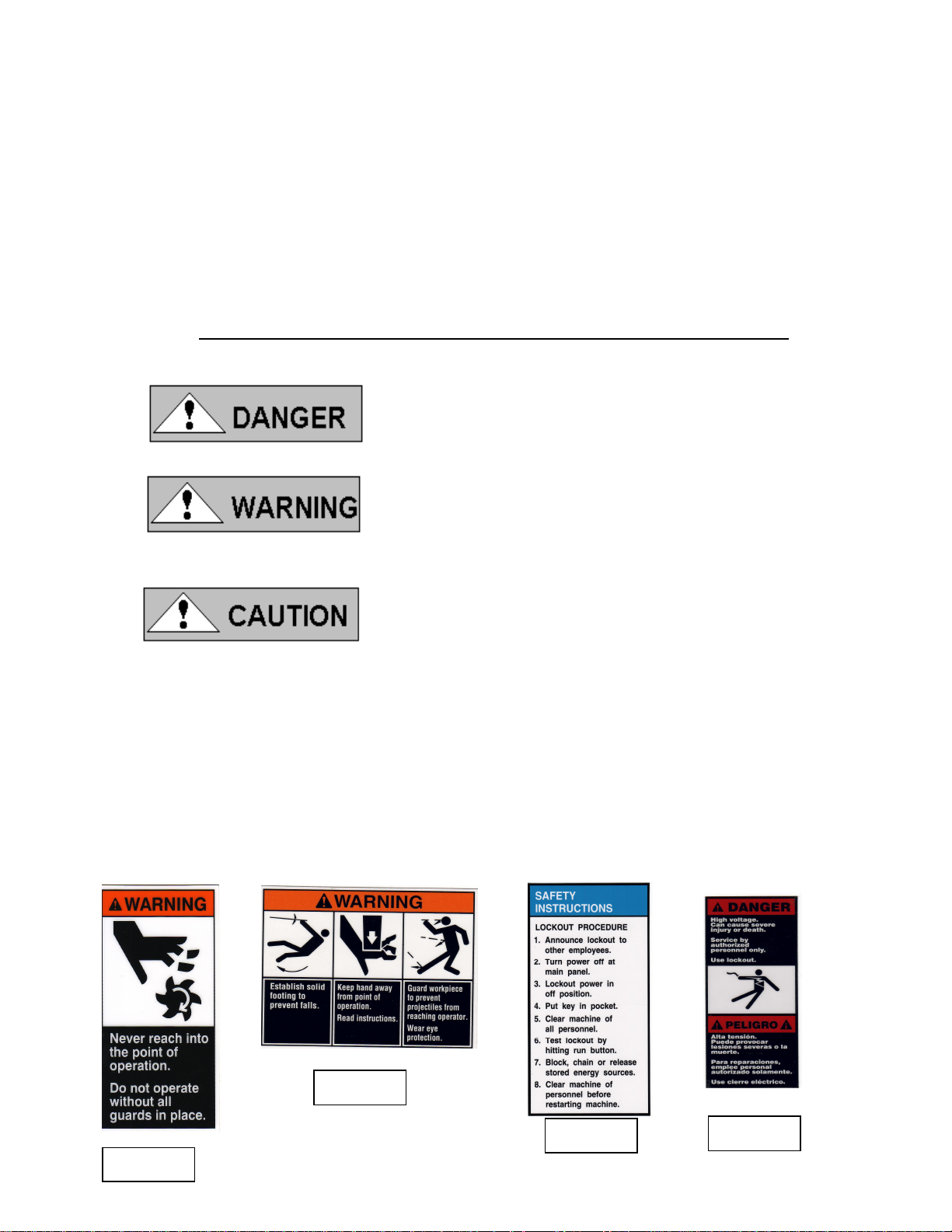
WARNING!!!
Extension cords and surge protectors are not recommended for this product.
3
Page 5
300168
82199
84605
84395
Ground fault circuit interrupters (GFCI) should not be used. DO NOT TAMPER
WITH WIRING OR SETTINGS INSIDE THE FREQUENCY DRIVE.
Do not open any cover or remove any guard without proper lockout of equipment.
Only a qualified electrician with proper PPE should perform electrical work on this
equipment.
Some components in this equipment may store electricity.
BEFORE USE, ALL SAFETY POINTS MUST BE READ AND UNDERSTOOD!
Operation of the drill press incorrectly, or in a dangerous
fashion can result in serious injury or death.
Operation of the drill press incorrectly, or in a
dangerous fashion can result in damage to machine or its
components and to the cutting tool.
Intend use:
The DRILL PRESS is designed to for drilling, boring
and tapping operations. Caution is required when
operating the drill press because it can be dangerous due to the high spindle
rotation speed. Operation hazards such as entanglement, shearing, ejection
parts ….etc. Guards such as pulley cover and chuck guard must in place and
working condition to prevent any hazard.
Please think about the safety warnings in the instruction manual before
operating the machine
Safety stickers
4
Page 6
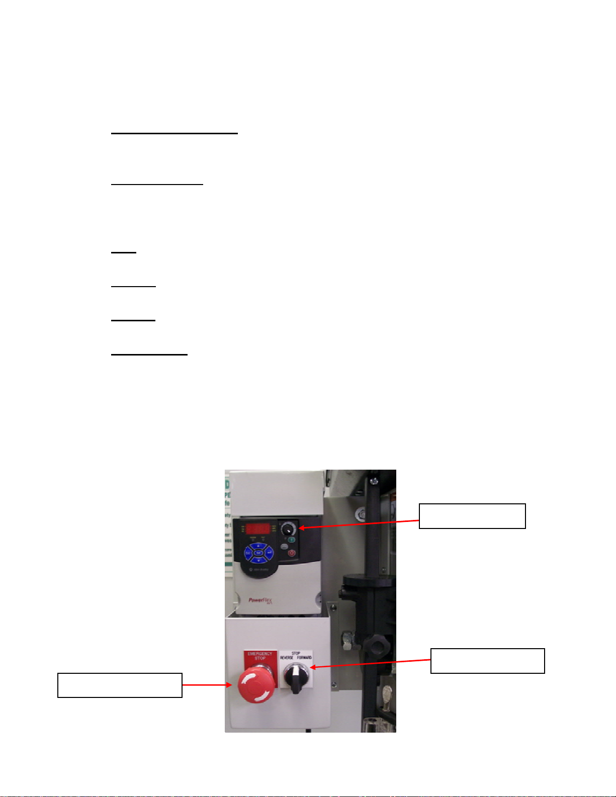
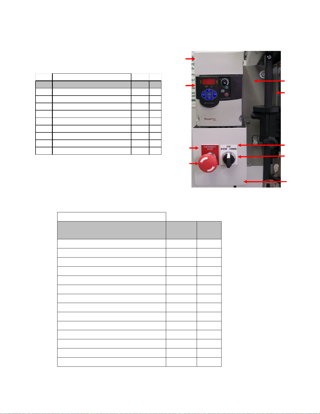
Familiarize yourself with the controls before operating.
Emergency stop button
When this is pressed the power to the motor and controls is disconnected. The
frequency drive stores energy this will remain lit for about 20 seconds.
Spindle direction
Turn the spindle direction switch to the desired direction forward, reverse or stop. If
the emergency stop button is pushed or if the power is lost you will have to move
this to stop (TO RESET) then to desired spindle direction.
Stop
This is used when you would like the spindle to stop.
Forward
This is used for standard drilling and tapping operations
Reverse
This is used for left hand tapping and to retract a tap during tapping operations.
Spindle speed
The black dial in the upper right hand corner controls the spindle speed. This will
change the speed in forward and reverse directions.
Warning!!!
Avoid stopping the motor under load or stalling the motor. This could damage
the electrical components.
Emergency stop button
Spindle speed dial
Spindle direction dial
5
Page 7

Tapping operations using the reverse feature
1. Drill the initial hole on the drill press for accuracy of diameter. If the diameter
is 1/2 inch or larger, drill a pilot hole about half that diameter first.
2. Make sure the hole has a large enough chamfer. If the chamfer is too small
the tap will work a little hard when starting the tapping operation.
3. Select the tap type. Choose from a taper tap (recommended), plug tap or
bottoming tap. The taper tap has several chamfer threads forming a tapered
cone on the inserting end. The plug tap has fewer chamfer threads and a
bottoming tap only has a couple chamfer threads.
4. Match the tap size. Use the specified tap size to thread the hole diameter.
Taps that are sold with drill bits are size matched for you. The taps
themselves may show the hole size they’re intended for, but it’s likely to be
given in metric notation. Use a conversion chart to match this with the inch
fractions measuring drill bits.
5. Cut the threads. Lubricate the tap with tapping fluid. Start the drill press and
lower the tap gently into the hole to be threaded. It only takes a few seconds
to tap a hole. When the tap gets to the desired depth reverse the direction of
the spindle and the tap will work its way out. As long as it has been set up
properly, the chances are good for success.
Tips for tapping
Tapping is a skill. It takes practice to do it well and to not break taps. If you’re
new to tapping, practice on sample stock before tapping into your actual
project
Materials have differing requirements for drill speed and lubrication. Hole
depths and diameters may present additional drilling requirements. Refer to
material charts for drilling specifications.
6
Page 8

1. OPERATION (PROCEDURE)
Drill / Chuck Installation:
To show greater detail
Chuck guard is in the open position in POWER MUST BE OFF BEFORE
photos. CHUCK GUARD MUST IN MAKING ANY ADJUSTMENTS!
PLACE DURING OPERATION!
TURN POWER OFF! Before inserting
drill bits, chucks or arbors, always clean
out spindle hole and taper hole with a
clean cloth.
Open chuck jaws completely by turning
attached chuck key counter-clockwise
until the jaws are fully opened.
To install the chuck to the arbor tightly,
slide the chuck into the taper forcing it
into the spindle with by hand. Place a
block of wood on the table then lower the
spindle to make contact with the wood
and press the chuck tightly into the
spindles taper.
Install a taper shaft drill bit into the taper
the same way as you would the chuck. If
an adaptor is used it must fit the taper
correctly and the bit must fit snug in the
adaptor.
Table lock Table height adjustment:
Table height adjustment is
accomplished by loosening the clamp
bolt then adjusting the table with the
bracket handle to desired height. After
table is at working height, retighten
the clamp bolt securely.
Note: Keep table adjustment rack
clean from debris. Never attempt to
move table with clamp bolt tightened.
Table handle
7
Page 9
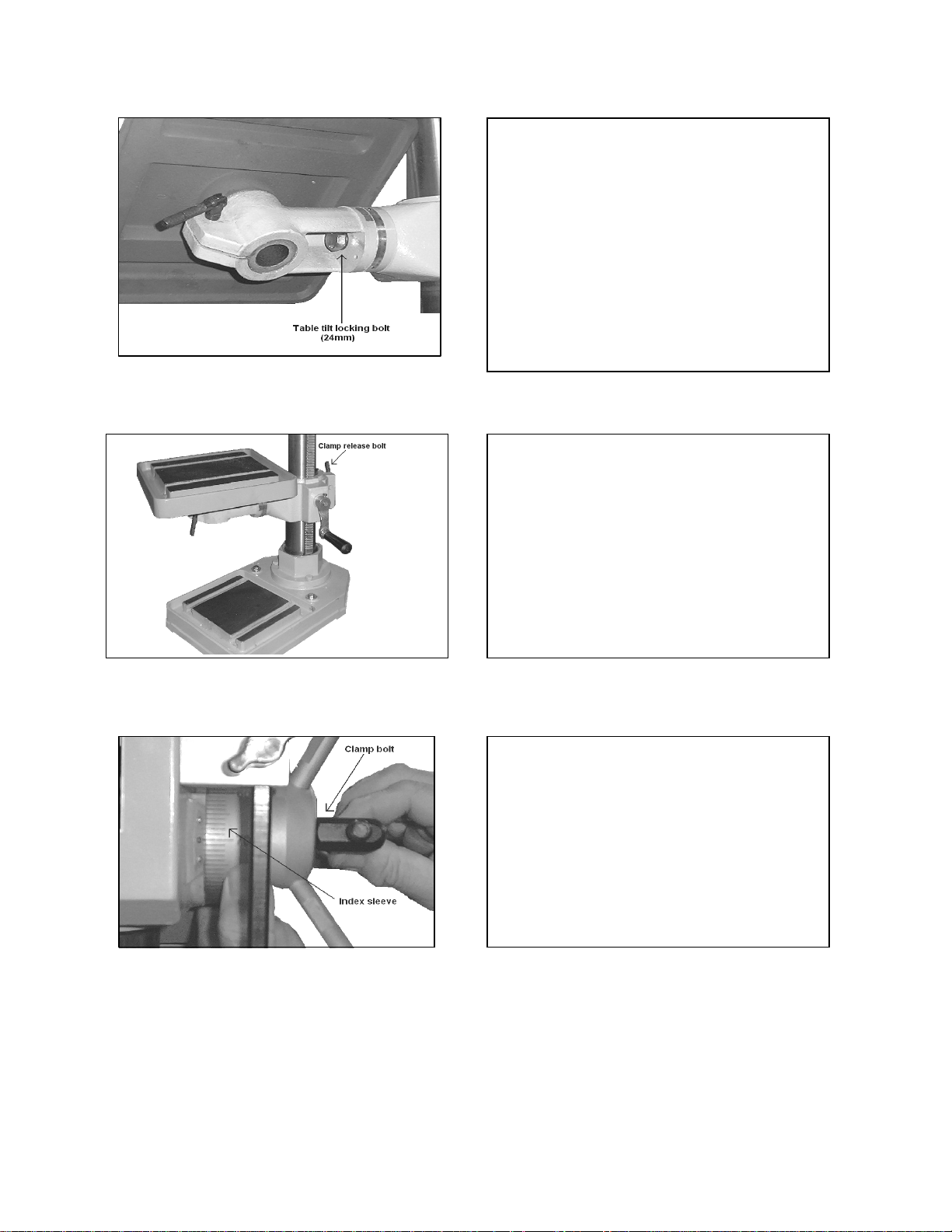
Table tilting adjustment:
Using an adjustable or box wrench
loosen table level lock bolt. Carefully tilt
the table to the degree needed, as shown
on the angle index scale located on the
table rotation point. Retighten nut
securely.
Note: Never tilt table if any material or
fixturing is on it. Only make adjustments
when table is free of loose articles.
Table swing adjustment:
To swing the table up to 360 degrees,
loosen the clamp release bolt and swing
table to the desired position. After the
table is in the correct position tighten
clamp release bolt securely.
Note: Never swing table if any material or
fixturing is on it. Only make adjustments
when table is free of loose articles.
Feed depth adjustment:
Setting the feed depth adjustment is
done by loosening the clamp bolt on the
spindle depth index sleeve and rotating
it to the desired depth.
Retighten clamp bolt securely.
Note: Never make this or other
adjustments when machine is running.
8
Page 10
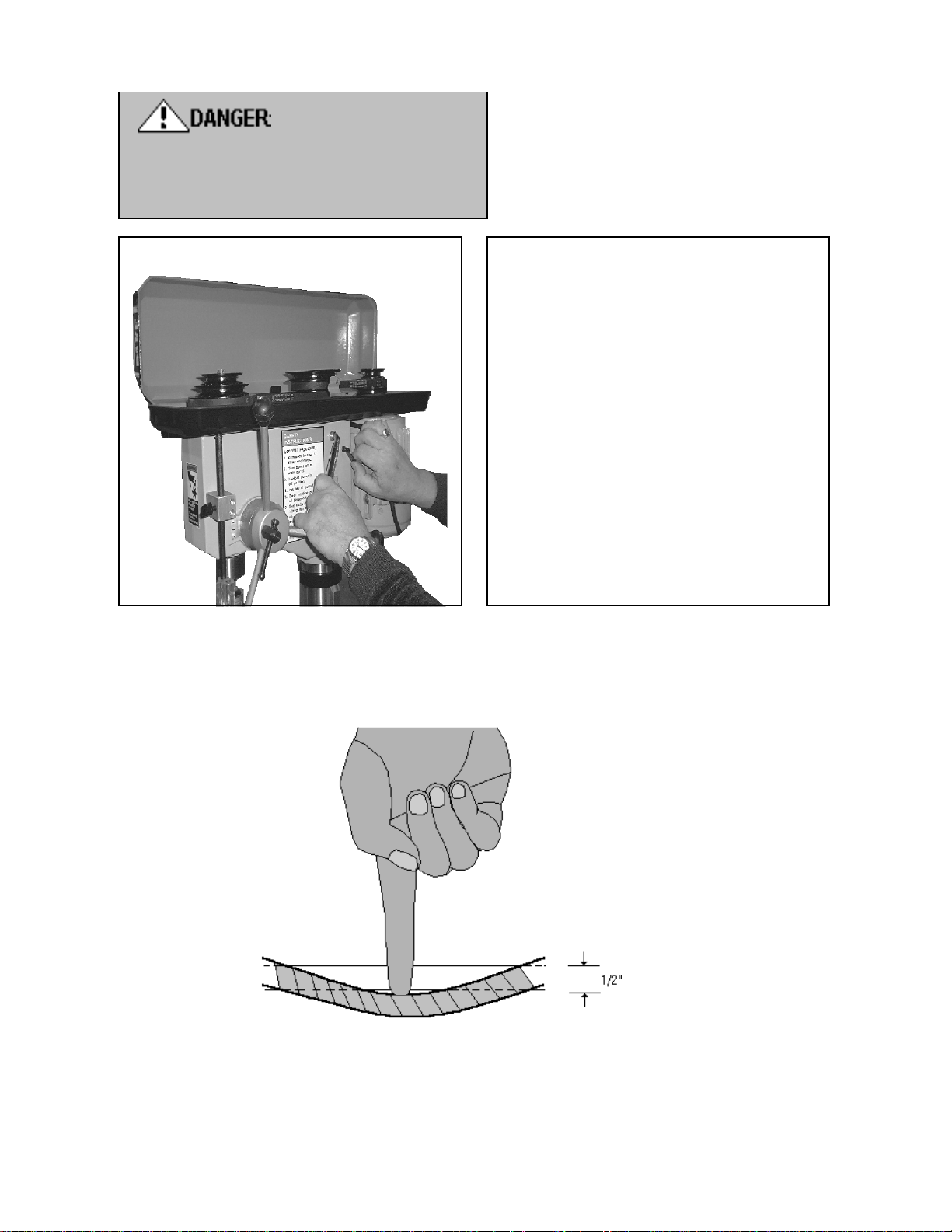
TURN POWER OFF!
Wait until machine has come to a
complete stop before proceeding with
speed change!
Speed adjustment:
Open the pulley cover to expose the
pulleys and drive belts.
Loosen the belt tension lock handles.
Choose the proper speed for the drilling
operation. Move the belt to the correct
step of the pulleys for the desired speed.
(See diagram on page 8) Push the motor
backwards until proper belt tension is
applied. (1/2” deflection as shown below
speed selection chart in this manual)
Retighten belt tension lock handle.
NOTE: If center pulley bracket does not
move freely, loosen spring loaded bolts
½ - ¾ turns.
BELT TENSION ADJUSTMENT
Proper belt tension is approx. 10 lbs. of pressure or deflection of about 1/2 “
9
Page 11

10
SPEED ADJUSTMENT
Model: SB-25V
RPMs
Pulley
Steps
1 - 7 46 92 133 168 225 264 312 354 397
1 - 6 73 140 206 268 335 408 471 551 602
2 - 7 79 152 225 302 378 457 530 610 680
1 - 5 98 199 305 395 502 593 695 795 888
2 - 6 120 231 348 463 576 690 806 922 1032
3 - 7 128 245 370 476 573 700 872 985 1104
2 - 4 255 509 745 988 1241 1489 1722 1960 2194
3 - 5 287 572 846 1110 1401 1665 1948 2220 2469
3 - 4 415 810 1205 1598 2007 2404 2780 3201 3550
@
10hz
RPMs
@
20hz
RPMs
@
30hz
RPMs
@
40hz
RPMs
@
50hz
RPMs
@
60hz
RPMs
@
70hz
RPMs
@ 80hz
RPMs
90hz
@
Page 12

11
The proper drill speed for a given drill bit size is as on following table:
Material
Type
Cast
Steel
Tool Steel Cast Iron Mild Steel Alum. &
Copper
SURFACE FEET PER MINUTE
s.f.m. s.f.m. s.f.m. s.f.m. s.f.m.
Drill Dia. 40 60 80 100 200
Inch
REVOLUTIONS PER MINUTE
1/16 2,445 3,665 4,890 6,110 12,225
1/8 1,220 1,835 2,445 3,055 6,110
3/16 815 1,220 1,630 2,035 4,075
1/4 610 915 1,220 1,530 3,055
5/16 490 735 980 1,220 2,445
3/8 405 610 815 1,020 2,035
7/16 350 525 700 870 1745
1/2 305 460 610 765 1,530
5/8 245 365 490 610 1,220
3/4 205 305 405 510 1,020
7/8 174 261 348 435 762
1 153 229 306 382 668
1-1/8 136 204 272 340 595
1-1/4 122 167 244 306 535
Page 13
12
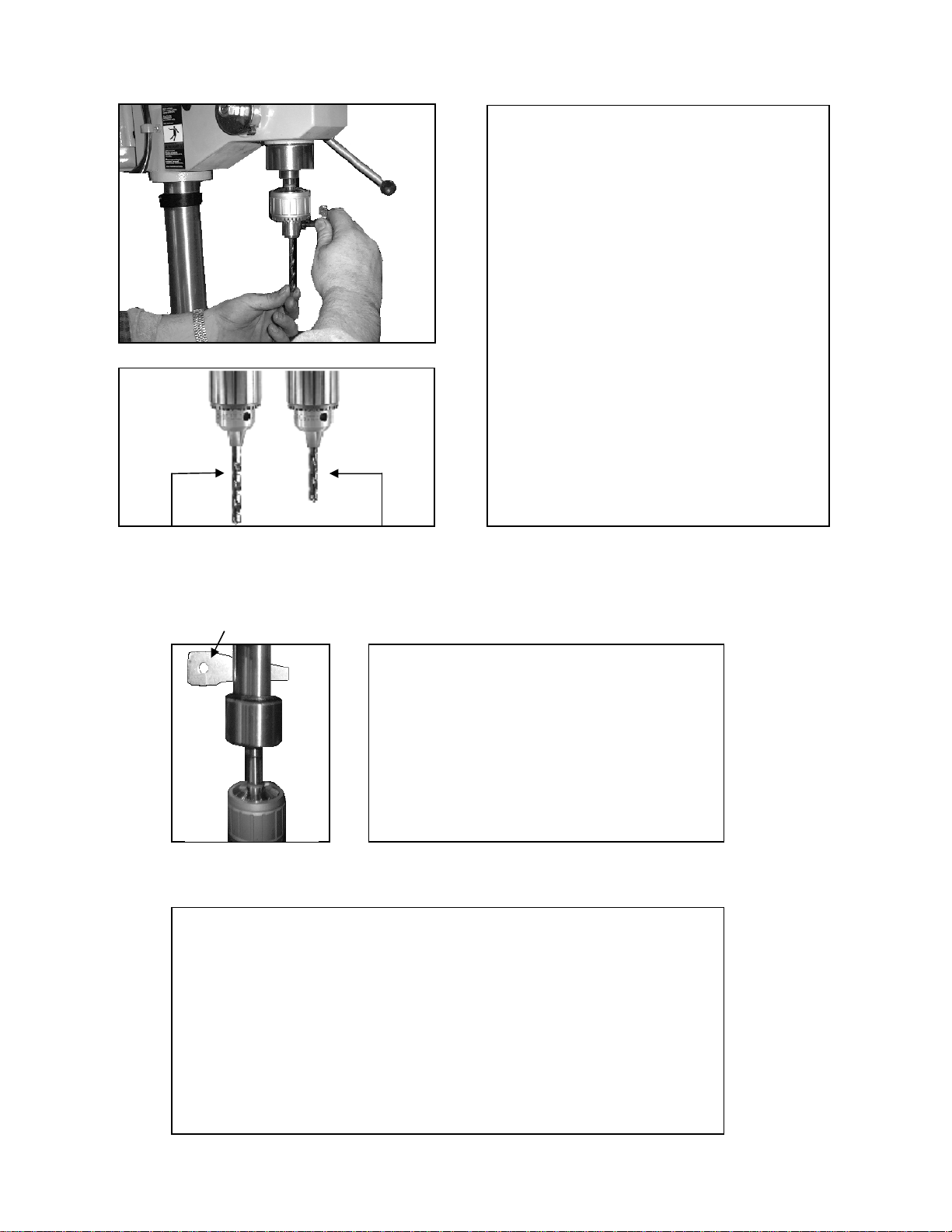
Installation of drill bits in the chuck:
A drill bit with a shaft of at least 1” long
should be used to allow correct chuck jaw
contact. If shaft length is less than 1” do
not insert bit as far into the chuck where it
allows jaw contact with drill flutes.
Center drill bit into the chuck and tighten
the chuck securely with the chuck key.
Note: Always use sharp, straight bits.
Never use bits with turned down shafts.
Never exceed the maximum diameter bit
size for the machine.
Always wear appropriate clothing while
operating the drill press.
All guards and interlocks must be in place
when operating the machine.
Correct: Jaws Incorrect: Jaws
contact drill shaft contact drill flutes
Wedge removal tool Tooling removal:
Before removing the chuck or bit from the
machine; be sure the spindle has come to
a complete stop and power is off. If needed
rotate spindle by hand to align the spindle
and quill openings. Insert the wedge
removal tool, while supporting the tooling
tap the wedge to remove the tooling.
Work holding:
When drilling directly on table surface, it is recommended that a
piece of wood or plywood be clamped securely to table under the
work piece. This will minimize splintering or burring as the drill breaks
through. It will help minimize drill bit and table damage.
Clamp the work piece to the table whenever possible. The table has
“T” slots that allow for many different clamping configurations.
When part cannot be affixed to the table a drill vise that is bolted to
Instructions page
Page 14

13
2. MAINTENANCE OF MACHINE
MAINTENANCE
1. On a regular basis blow out any dust that may accumulate inside
the motor. (Frequency depends on environment the machine is
in)
2. A coat of automotive wax applied to the table and column will help
to keep the surface clean.
3. All of the ball bearings are packed with grease at the factory. They
require no further lubrication.
4. Periodically lubricate the gear and rack table elevation
mechanism, the spindle splines and the rack (teeth on the quill).
5. After each use the machine should be cleaned. Weekly
lubrication of all sliding or moving parts with light weight or way oil
is recommended. For your own safely, turn switch “OFF” and
remove plug from power source outlet before maintaining or
lubricating your drill press.
Page 15

14
SB 32V
Page 16

15
PARTS LIST for SB-32V
Item
No.
1 Base 301041
2 Flange 301043
3
4 Screw 300999
5 Column 301045
6 Rack 301046
7 Handle 301048
8 Clamp Bolt 301049
9 Clamp Bolt 301051
10 Table Arm 301053
11 Table Bracket 301054
12 Worm 301056
13 Collar 301058
14 Feed Handle (3x) 301059
Description Part #
Spring Washer
13 mm 29 Belt 301066
(4x)
Item
No.
27 Spring & Cap 301064
28 Motor Pulley 301065
30 Screw (4x) 300998
31 Pulley Cover 301068
32 Insert Pulley Nut 301086
33 Spindle Pulley 301087
34 Insert Pulley Shaft 302217
35 Middle Pulley 301090
36 Screw & Spring (2x) 301092
37 Belt 301093
38 Middle Pulley Shaft 301094
39 Bearing 6203Z 300987
40 Bearing 6203Z 300987
Description Part #
15 Lock Handle 301070
16 Feed Head 301069
17 Spindle Scale 301072
18 Feed Shaft 301074
19 Belt Adjust Handle 301076
20 Wing Bolt 301078
21 Road - A 301080
22 Motor Plate 301081
23 Road - B 301083
24 Head 301084
25 Spring Base N/A N/A Chuck 16mm 301966
26 Switch 301062 N/A Key 16mm 301967
41 Table 301096
42 Quill 2.98" 301097
6006Z & 6208Z (SB-32)
43
Bearing
44 Spindle 301100
45 Arbor 301102
46 Seal N/A
47 Wedge 301103
48 Belt Cover Interlock Switch 300992
49 Motor 300994
50 Plexiglas Chuck Guard 300995
300989
Page 17
16
5.
9.
8.
6.
ADDITIONAL PARTS LIST
1.
Item # Part name Part # Qty.
1 Top cover 87377 1
2 Drive unit 302704 1
3 Name plate emergency stop 301904 1
4 Emergency stop button 716538 1
5 Back mounting plate 87378 1
6 Bracket 87382 1
7 Name plate reverse stop forward 302746 1
8 Selector Switch 302730 1
9 Switch mounting box 87379 1
Parts list
Parts list items not shown
2.
Part
3.
4.
7.
Part name
Cord set with plug 300529 1
Motor grommet 300540 1
Contact block N.O. 301782 2
Metal latch 301785 1
Cable 4 wire 302683 1
Hex bolt for mounting bracket 5/16-18 x 3/4 43314 2
washer for mounting bracket 5/16 flat 43632 2
Lock washer for mounting bracket 5/16 43644 2
Nut for mounting bracket 5/16-18 heavy 43911 2
Top mounting screws top bracket #10-24 x 1/2 43847 2
Nut for top mounting screws #10-24 43905 2
Screws self-tapping 43881 7
Connector cord 75151 2
Locknut conduit 1/2" 75257 2
number Quantity
Page 18

17
TROUBLESHOOTING GUIDE
Problem Possible Cause Remedy
Machine does not turn on Not plugged in Plug into proper receptacle
Frequency drive has error Clear error by turning off then back on
Too long or not correct extension
cord
Emergency stop button is activated Deactivate emergency button
Belt cover is operation Close belt cover
Noisy Operation Incorrect belt tension Adjust tension (page 8)
Loose Spindle or motor pulley
Spindle bearing worn Replace bearing
Chuck or Quill falls out Rust inhibitor, dirt, debris in or on
quill or spindle taper
Spindle does not move up or
down Belt broken or slipping
Debris in quill Clean quill and teeth
Feed depth adjustment is set see page 7 for adjustment
Spindle does not rotate Belt tension not tight enough Tighten belt tension page 8
Belt is broken or too worn Replace belt
Motor is not rotating Troubleshoot motor
Remove extension cord and plug directly
into receptacle
Check for wear or if pulley can be
tightened
Clean chuck and quill
Check belt for damage, Check for proper
belt tension page 8
Taper is slipping in spindle Clean chuck and quill
Page 19

18
ELECTRICAL WARNING
1. In the event of a malfunction or breakdown, grounding provides a path of
least resistance for electric current to reduce the risk of electric shock.
This machine is equipped with an electric cord having an equipment
grounding conductor. The proper plug must be used that is properly
installed and grounded in accordance with all local codes and
ordinances.
2. Do not modify the plug provided. If it will not fit the outlet, have the proper
outlet installed by a qualified electrician.
3. Improper connection of the equipment grounding can result in a risk of
electric shock. The conductor with insulation having an outer surface that
is green with yellow stripes is equipment grounding conductor. If repair or
replacement of the electric cord or plug is necessary, do not connect the
equipment grounding conductor to a live terminal.
4. Check with a qualified electrician or serviceman if the grounding
instructions are not completely understood, or if in doubt as whether the
machine is properly grounded.
5. It is not recommended to use an extension cord on this machine. If one
must be used, use only a grounded cord of proper size for machine and
length of run needed.
6. Repair or replace damaged or worn cords immediately.
Page 20
19
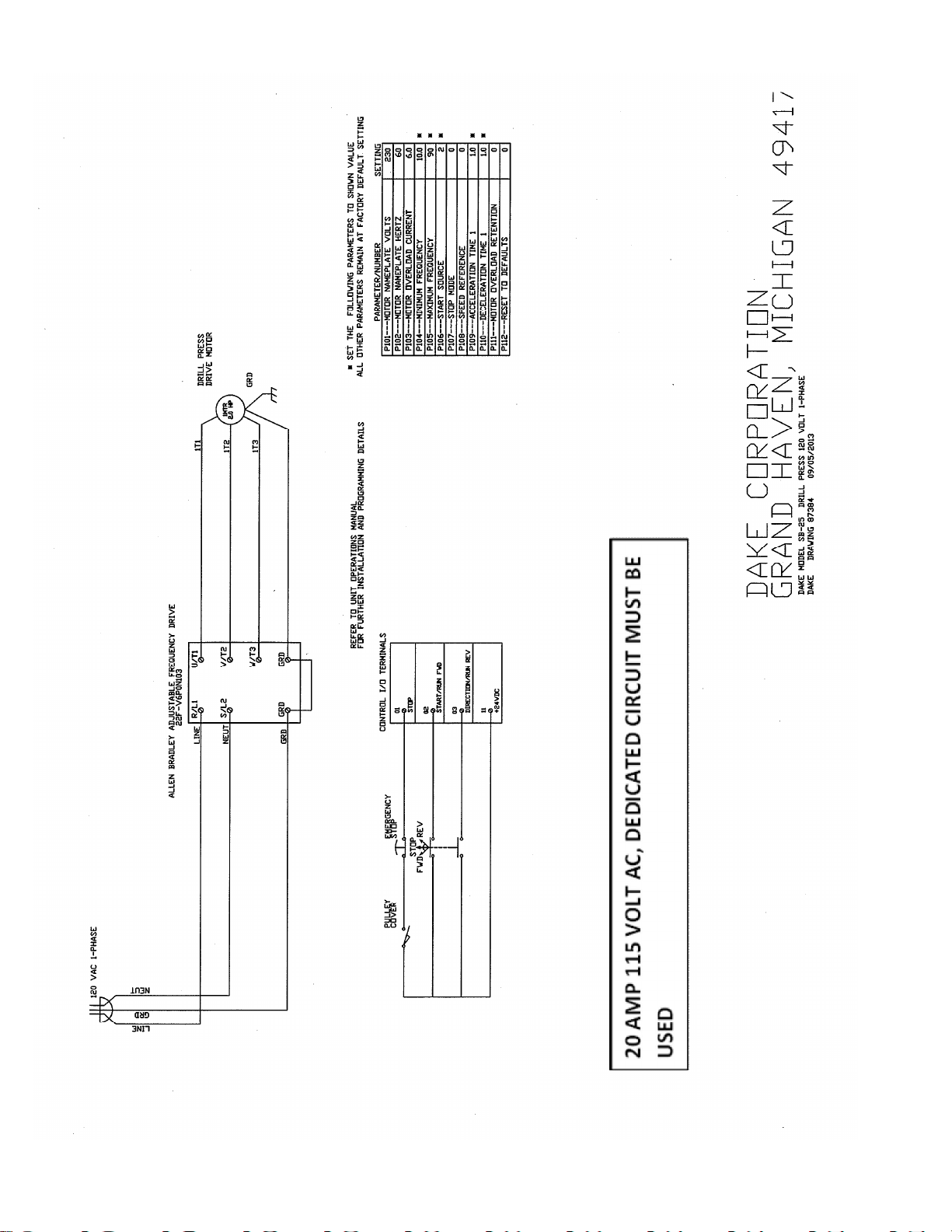
ELECTRICAL DIAGRAM
 Loading...