

Page 1
Operator’s Manual and Part’s List
Model G-75
Belt Grinder
3/14/2011
Serial No: _______________
Date Purchased: ______________
DAKE Division of JSJ
724 Robbins Road
Grand Haven, MI 49417
Phone: 1-800-937-3253 616-842-7110
Fax: 1-800-846-3253 616-842-0859
E-mail: customerservice@dakecorp.com
technicalservice@dakecorp.com
Web: www.dakecorp.com
Model G-75 1
Page 2

3/14/2011
Table of Contents
Page
1. Machine placement / Set Up / Installation: 3-5
1.1 Anchoring of the machine 3
1.2 Power hook up 3
1.3 Start up 3-4
1.4 Adjustments for operation 4
1.5 Belt installation / Tracking 4-5
2. Machine Safety 6
2.1 Do’s and Do Not’s 6
3 Machine Operation 7-8
3.1 Adjusting working height 7
3.2 Adjusting tool / material holders 7
3.3 Grinding material operations 8
4 Cleaning and Maintenance 8
5 Machine Specifications 8-9
5.1 Machine part descriptions 9
6 Warranty 9
7 Diagrams and Parts Lists 10-11
Model G-75 2
Page 3
MACHINE PLACEMENT/ SET UP / INSTALLATION
1. Machine Placement:
1.1 Anchoring the machine:
NOTE: Machine must be located away from flammable areas, congested areas, traffic
areas, and areas where others will be working!
Grinder exhaust should always face an area that is unoccupied, never toward other workers, aisles or
areas that contain waste containers, rags, etc.
Grinder should always be positioned so operator can be accessible to all sides and that there are no
trip hazards or liquids present.
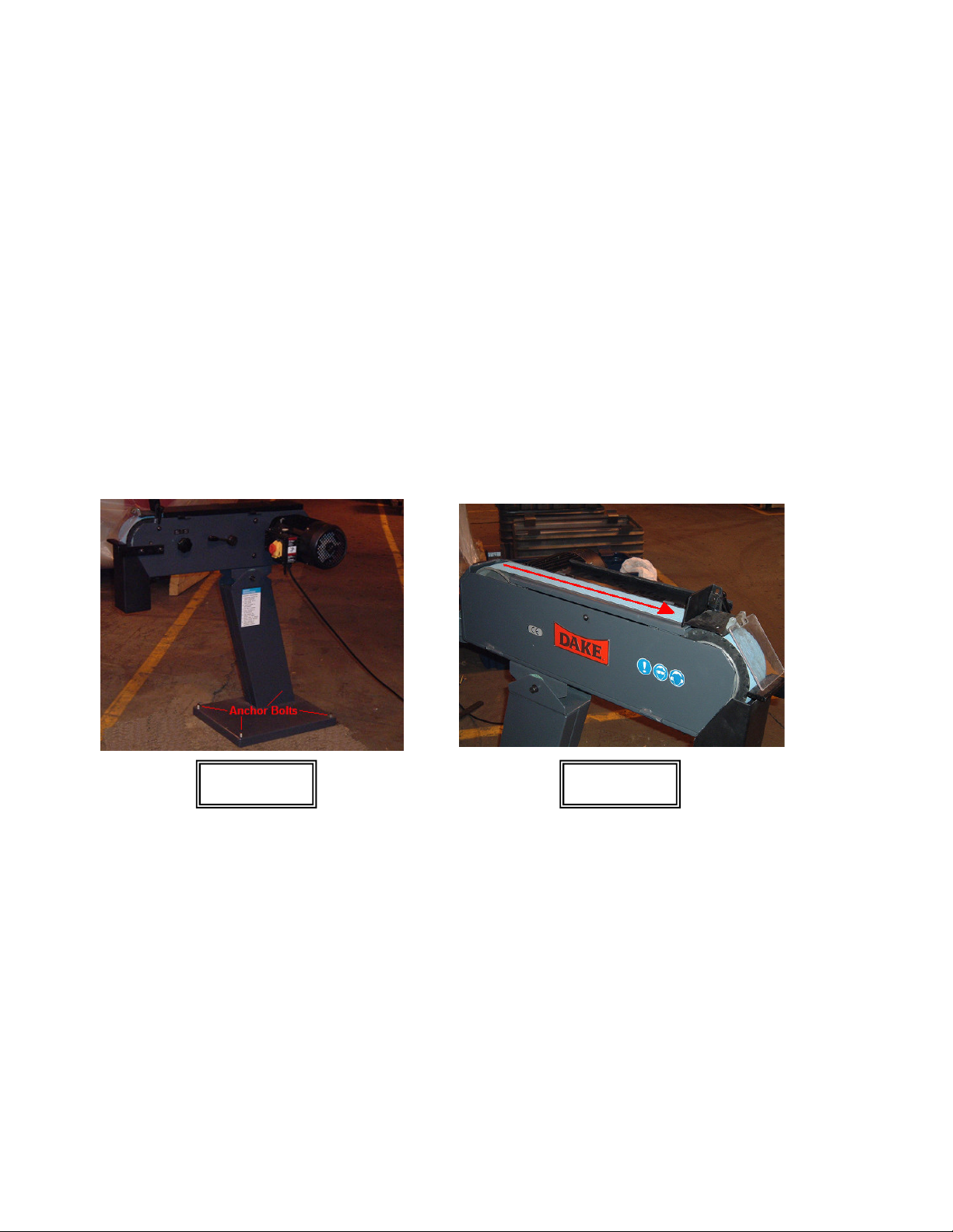
Grinder must be anchored on a level hard surface! Machine must be removed from the pallet.
Anchoring of the machine must be done to prevent movement of the unit during operation. The base is
supplied with four mounting holes on the four corners. (Figure 1) Anchoring must be done in a suitable
fashion.
Figure 1 Figure 2
1.2 Power Hook Up:
NOTE: Before connecting power make sure power is OFF and make sure there are no
damaged parts on the machine, and that all components (wheels and belts) move freely and
are not rubbing on material rests etc.!
Correct Belt Rotation
3/14/2011
A qualified electrician must do connection of power to this machine. Machine is supplied
with a power cord that cam have a plug installed or can be hardwired into a suitable power
source. 20-amp service is recommended for this machine.
Rotation on this machine must be in the correct direction. The belt is to travel forward from the
motor end of the unit. (Figure 2) If rotation is incorrect simply reverse to leads from the
incoming power.
This machine is equipped with CE certified components with low voltage drop out, and flip up
start feature to prevent accidental starting.
Model G-75 3
Page 4

3/14/2011
For phase converter connections please refer to the manufactures instructions.
1.3 Start Up:
To start the machine on the motor is the start switch. In order to start the machine the yellow
lock out door must be raised and the green start button pushed. (This prevents accidental start
up) The yellow door must remain open until you wish to stop the machine; this can be done by
either pushing the red button or pushing down on the door or E-stop button on the door.
(Figure 3) To lock the machine out simply snap the yellow door close until it latches and insert
lock out through the slot in the switch base.
1.4 Adjusting the machine for operation:
NOTE: Do not operate this machine until all adjustments have been made and you have
read the safety instructions!
Front tool / material rest must be adjusted approx. 1/16” (gap) from the contact wheel. Tool rest
must be tightened. (Figure 4)
Plexiglas eye shield must be set for the material you are grinding. This shield should be as
close to the material as possible without restricting grinding operation, approx. 1/8” – 1/4”
(Figure 4)
Spark catch box must be installed toward the back of the machine as far as it will go. (Figure 4)
1.5 Belt Installation / tracking:
NOTE: Turn off power and lock out whenever changing or installing grinding belt!
Always use high quality belts of the correct size!
Model G-75 4
Figure 3
Figure 4
Page 5

3/14/2011
Belt must be installed are tracked properly to ensure best performance, longest belt life, safety,
and to prevent premature wear to the machines components.
1. Installation begins with loosening the spark catch box and sliding it towards the front of the
machine and locking it in that position to gain belt clearance or by removing it from the
machine. (Figure 5) Remember to reinstall this box before use. (This is a good opportunity to
empty the slag from the box)
2. Open access door on the left hand side of the machine. Turn Allen bolt and carefully lower the
door. Open the top belt guard and swing it open to the right. Note: When opening this door the
rear flap must be opened and folded forward. (Figure 6)
3. Release the tension release handle on the motor side of the machine. Moving this forward and
down releases the belt tension. The tension is released by moving the motor forward. (Figure
7)
4. Remove the old belt by pulling it outward from the drive and contact wheels. You may need to
maneuver the belt around the machines door hinges and upper angle guide plate. (Figure 8)
NOTE: Arrows on belt must be pointing in direction of rotation!
Model G-75 5
Figure 5
Figure 7
Figure 6
Figure 8
Page 6

3/14/2011
5. Discard old belt. Install new belt in reverse order making sure the arrows printed on the
inside of the belt are going in the direction on rotation. If belt is reversed the seam of the belt
can be damaged causing premature belt failure. Loop the belt around
the contact are drive wheel, try to keep it centered.
6. Once belt is in position, using the belt tension handle pull the handle up which moves the
motor back putting proper tension on the new belt. Make sure handle is engaged fully. Close
all doors and covers on the machine and readjust the spark catch box, and tool rest.
7. With all the doors closed except the top cover
and before power is restored to the machine visually
look at the placement of the belt on the contact
wheel. If the belt is close to being centered by hand
carefully push the belt in direction of rotation. This
will show you how much tracking is needed. If the
belt does not move too much left or right, close the
top cover and restore power. Quickly jog the
machine and watch where the belt is tracking. The
belt must track in the center of the contact wheel as
seen in figure 9. If the belt is tracking off as seen in
figure 10 adjustments must be made as described in
step 8.
8. Tracking of the must be done to prevent the belt from walking on the contact wheel and cutting
into the side of the machine or causing shredding of the belt. Start the machine and make your
tracking adjustment by turning the tracking knob on the motor side of the machine in very small
increments until the belt runs center on the contact wheel. The knob is labeled left and right as
to what direction the belt will move with each adjustment. (Figure 11)
NOTE: When a new belt is installed there should be a break-in
period so the belt will wear in evenly. For the first 5 minutes of
use lighter pressure should be used!
2. Safety:
2.1 Dress properly / Do’s and Do Not’s:
1. Do wear approved safety glasses with side shields, or full-face shield is
recommended.
2. Do wear non-slip foot ware. Do not over reach! Keep a safe footing.
3. Do wear a dust mask if material being ground is dusty.
4. Do wear hearing protection.
5. Do keep guards in place and in good condition. Lock machine out if guards or
Figure 9 Figure 10
Figure 11
Model G-75 6
Page 7

components are broken or missing. Replace any worn or broken parts without delay.
6. Do make sure the incoming power supply is up to codes and kept in good condition.
7. Do always wait until belt has stopped completely before opening covers / doors,
reaching into point of operation or making adjustments.
8. Do use good quality belts of the right size. Change belts when needed. If the belts
are worn, burnt, frayed or cut they must be changed.
9. Do use the tool rest or angle guide when grinding. Do not free hand.
10. Do keep hands away from the belt and parts of material being ground. The hot parts
can burn you.
11. Do keep all work surfaces and spark catch box clean.
12. Do adjust the machine for a comfortable work height.
13. Do keep area of machine well lit.
14. Do keep all visitors and children a safe distance from machine.
15. Do anchor the machine to a solid level floor.
16. Do not wear loose clothing, jewelry, neck ties, rings, loose long hair, gloves, or
clothing that will burn easily.
17. Do not force the work. Too much pressure or hard jabs can cause injury, ruin the
belt, create excessive heat.
18. Do not use grinder if persons are close to the exhaust end of the machine.
19. Do not operate machine if the spark catch box is not installed. Fire Hazard!
20. Do not operate the machine if under the influence of drugs, alcohol, or medications.
21. Do not use machine for purposes that it was not intended for. Do not force the
material.
22. Do not leave the machine running unattended. Always turn off machine and wait for
it to stop before walking away.
3. Operation of the machine:
3.1 Adjusting the machine for comfortable height.
1. Loosen the head tilt lock bolt on the pivoting point of the base. Do not loosen too much
that the grinding head tilts too freely. With this bolt loosened tilt the grinding head up or
down to suit your needs. Securely tighten this bolt. (Figure 12)
Model G-75 7
Figure 12
3/14/2011
Page 8

3.2 Adjustment of tool / material holder and angle guide plate.
1. Adjustment of tool / material rest and eye guard is outlined in section 1.4 and figure 4
2. Adjustment of upper angle guide. This guide is to be used as a guide when grinding
across the surface of the belt. This feature allows you to grind long or flat pieces of
material without obstructions. (Figure 14) The guide must be used to prevent the material
from getting away from you and causing possible injury. This guide can also be used at
an angle for grinding bevels on material. This adjustment is made by opening the top
cover (Rear cover flap must be folded forward before cover will open all the way. This
cover will rest on the motor) loosen the locking handle on the motor side of the machine
on the guide. Angle this guide to the angle you require by moving it up or down and
setting the desired angle. Make sure this guide is not on the belt but slightly above it.
Lock the handle down. (Figure 13) NOTE: When grinding on the surface use extreme
caution and safety measures!
3.3 Grinding of material:
1. Always introduce the material to the belt with a slow motion. Do not jab the material into
the belt. Doing this can cause the belt to tear or cut. Once contact is made with the belt
keep a firm steady pressure on it. Do not apply so much pressure that it causes the motor
to bog down. This creates excessive heat, contact wheel wear, belt wear and could cause
motor damage. Always hold the material with both hands! Always use the tool /
material rest or guide surfaces! Never make adjustments while the machine is
running!
Model G-75 8
Figure13
Figure 14
3/14/2011
Page 9

4. Cleaning and Maintenance:
1. After every use clean the machine thoroughly. If using compressed air take extra care.
Keep contact wheel and vent grooves clean, upper grinding surface clean especially the
graphite strip under the belt. Sweep floor around machine to prevent build up of grinding
dust.
2. Routine Maintenance consist of frequent cleaning, replacement of contact wheel when
needed, keeping all fasteners tight, emptying the spark catch box often. Replace any
worn parts without delay. Keep Plexiglas eye guard clean, and replace when necessary.
3. After time the graphite wear strip may need to be
changed. (Figure 15) This is done by
removing the old strip with a putty knife and cleaning
the surface. Using contact cement the new strip can
be glued into place. NOTE: Never use the machine
if the graphite wear strip is damaged or missing!
4. TIP: Exhaust from the grinder will throw sparks a
good distance and should be controlled. One way of
keeping the area safe and clean is to install a metal
elbow (such as used on dryer vents) to the exhaust
flange on the back of the grinder head. This elbow is
then directed downward into a bucket of water. This
keeps sparks from flying outward, cools the material
slag and keeps dust to a minimum.
5. Machine specifications:
Machine type Horizontal belt grinder
Belt size 3” x 79”
Horse Power 4 HP
Contact wheel size 3” x 8”
Belt speed 6600 f.p.m.
Grinding plane 3” x 21”
Electrical components CE approved
Weight 187 lbs.
Work height 18 - 48 in.
Base dimensions 17 x 21 in.
Machine width 22 in.
Machine length 39 in.
Over all height 43 in.
Noise levels 85 dB @ no load
Figure 15
3/14/2011
Model G-75 9
Page 10

3/14/2011
5.1 Machine part descriptions:
1. Spark catch box 2. Spark catch box lock knob 3. Tracking adjustment
4. Belt tension release 5. Motor 6. Exhaust port
7. Start switch 8. Tool / material rest 9. Angle guide handle
10. Plexiglas eye shield 11. Height adjustment bolt 12. Top cover and flap
13. Angle / work guide 14. Contact wheel 15. Drive / Steering wheel
16. Side cover
6.
Warranty:
WARRANTY: If, within a period of one (1) year from date of shipment, any part of any
equipment sold by Dake is defective in material or workmanship and is so found after
inspection by Dake, it will be replaced or repaired at the option of Dake, providing the
equipment has been given normal and proper usage and is still the property of the original
Purchaser. Purchased components such as Micro Drop mist system or the like, installed as
a part of Dake equipment are warranted only to the extent of the original Manufacturer’s
warranty. Dake is not responsible for any service work performed unless authorized in
advance.
THE FOREGOING WARRANTY IS EXCLUSIVE AND IN LIEU OF ALL OTHER
WARRANTIES WHETHER WRITTEN, ORAL OR IMPLIED (INCLUDING ANY
WARRANTY OF MERCHANTABILITY OR FITNESS FOR PARTICULAR PURPOSE).
UNDER NO CIRCUMSTANCES SHALL DAKE BE LIABLE FOR ANY INCIDENTAL OR
CONSEQUENTIAL DAMAGES.
NOTES: _____
Model G-75 10
Page 11

7.
Diagram and Parts List:
3/14/2011
Model G-75
Model G-75 11
Page 12

Model G-75 Parts List
Item
1 Stand 301488 1
2 Hex. screw M12x30 2
3 Washer 2
4 Paper spacer 301489 2
5 Clamp for angle &
6 Nut M10 4
7 Washer 4
8 Washer 4
9 Hex. Screw M10x20 4
10 Hex. Screw M5x10 2
11 Washer 2
12 Hex. Screw M12x50 2
13 Body 301490 1
14 Motor 220 volt 3 phase 301491 1
14 Motor 220 1 phase 301815
15 Washer 1
16 Belt tension release
17 Inner hex. Screw M8x20 1
18 Belt tension release
19 Sleeve, handle 301494 1
20 Shaft 301551 1
21 Belt guard with flap 301552 1
22 Tracking adjust knob 301553 1
23 Washer 1
24 Graphite wear strip 301554 1
25 Nut 2
26 Hex. Screw M10x15 3
27 Washer 2
28 Top work support 301495 1
29 Top work support plate 301496 1
30 Lock handle 301497 1
31 Washer 1
32 Eye protector base 301498 1
33 Screw M5x8 2
34 Hex. Screw M5x50 1
35 Screw M4x12 2
36 Eye protector hinge 301499 1
37 Eye protector, clear 301500 1
38 Nut M4 2
39 Block with thread 301501 1
40 Contact wheel 301555 1
41 Hex. Screw M10x15 2
42 Washer 2
60 Grit belt 77021
Description Part No Qty
301550 2
height adjustment
301492 1
base
301493 1
lever
3/14/2011
Item
43 Work support 1
44 Screw M5x16 1
45 Stop ring 301502 2
46 Bearing 301643 2
47 Shaft, axle 301503 1
48 Spacer, bushing 301504 2
49 Motor support 301505 1
50 Nut 1
51 Butterfly spring 301556 1
52 Screw bar 301506 1
53 Washer 2
54 Base 301507 1
55 Screw M6x25 2
56 Shaft 301508 1
57 Roll Pin 1
58 Eccentric wheel 301509 1
59 Washer 4
60 Bolt M8x22 4
61 Spring 301510 2
62 Spring 301512 2
63 Roll pin 301511 2
64 Pin shaft 301513 1
65 Stop ring 301514 3
66 Draw bar 301515 1
67 Butterfly spring 301516 12
68 Support 301517 1
69 Belt adjustment device 301518 1
70 Screw 1
71 Protect buckle 301519 1
72 Butterfly spring 301520 2
73 Screw M10x30 1
74 Washer 1
75 Side cover 301521 1
76 Bolt M10x30 1
77 Washer 1
78 Steering/drive wheel 301522 1
79 Spark catch box 301523 1
80 Bolt M8x15 1
81 Washer 1
82 Knob, spark catch box 301524 1
83 Fixture plate 301577 1
84 On/off switch (see elect. Diagram) 1
40 Grit belt 77010
Description Part No Qty
Model G-75 12
Page 13

3/14/2011
Part number Part name Qty.
302062 Starter Enclosure 1
302063 Under voltage protection 1
302065 3 phase starter 10-16 amp 1
301781 1 phase starter 16-20 amp 1
302236 Start capacitor 1 phase only (300 mfd) 1
302381 Run capacitor 1 phase only (40 mfd) 1
Model G-75 13
 Loading...