

Page 1

1
INSTRUCTIONS AND PARTS
LIST FOR MODEL 25H
HAND-OPERATED HYDRAULIC PRESS
SETTING UP THE PRESS FOR OPERATION
For shipping convenience, the gauge, pump handle, hoist crank, screw nose and base angles were removed
from the press. Assemble these parts to the press in the following order:
1. Bolt the base angles to the uprights using the four bolts and nuts furnished. Shoulder the base angles
against the stops on the uprights.
2. Install the pressure gauge using a hydraulic sealant to ensure a sealed fit.
3. Insert pump handle into handle socket and fasten in place by means of the setscrew on top of the handle
socket.
4. CAUTION! Place the hoist crank on the lift drum shaft. The table is raised to the desired height by
turning the crank after removing the table pins. Check to make sure the hoist cable is tracking
correctly. Run the table channels from top to bottom. The cable should be on each of the two
upper pulleys and should track back and forth on the cable drum. Always place table pins under
the table channels before releasing the hoist crank when positioning the table channels for cable
tracking, servicing, or set-up for desired work opening. If a tracking problem exists, contact the
Dake factory for instructions. Be sure all table pins are fully inserted in place before applying
pressure. Always remove or release pressure on the cable before pressure is applied.
5. Fasten nosepiece to the end of the screw using the thumbscrew included.
OPERATIONS AND CONTROLS
The operator should acquaint himself with the use of the following controls:
A. Insert 4 table pins
B. Close release valve
C. Leave a gap of ½” between bumper and reservoir
D. Keep portion of screw extending beyond the ram as short as possible
1. The pump handle is the pressure supply source and is manually operated with an up and down motion.
2. Item number 41 (part no.10631) is the release valve handwheel. Always keep it firmly closed when
operating the press and it should only be opened when releasing the pressure to allow the ram to return.
3. By turning Item 33 (Part No. 716518), the ram screw can be adjusted in or out of the piston assembly.
Always keep the portion of the screw extending out of the piston as short as possible. It is advisable to
raise the table one or two sets of holes rather than running the screw out to its limit of travel. NEVER
EXCEED THE RECOMMENDED STROKE OF 5 INCHES FOR THIS PRESS. EXCEEDING THE
STROKE WILL CAUSE DAMAGE TO THE INNER PACKINGS.
4. The two combination table plates-v blocks provided are used for supporting the work piece.
5. Always pump piston down ½” before nose piece comes in contact with work. Damage to piston may
occur.
FILLING THE PRESS WITH OIL
It is extremely important that new, clean, light hydraulic oil be used in this press, Mobil DTE 24 or an
equivalent. It is strongly recommended that the oil be filtered to remove any possible dirt. The piston should
be in its maximum upper position when filling the reservoir. Fill the reservoir with 2 ½ quarts of oil. UNDER
NO CIRCUMSTANCES USE OLD DIRTY OIL. Next remove the screw plug from the top of the cylinder and fill
with oil. Close the release valve handwheel and pump oil into the workhead until oil is visible in the top of the
cylinder. This will remove all air from the chamber above the piston. Then install the gauge. If oil leaks by the
piston. The reservoir should be drained and refilled (2 ½ quarts of oil) with the piston in the top position.
25H Press 10/2015
Page 2

2
SAFEGUARDING THE POINT OF OPERATION
ANSI B11.2 – Hydraulic Power Presses
Safety Requirements for Construction, Care and Use
It is important that Dake press users have a clear understanding of their responsibility involving the care and use
of their Dake hydraulic press, including point-of-operation safe guards. Dake strongly recommends that Dake
press users obtain a copy of the current American National Standard Institute (ANSI) B11.2 standard, for a
more complete understanding of their responsibilities.
ANSI B11.2 states the following, relative to point of operation safeguarding:
“Normally, only the employer (press user) can determine the requirements of the press productions system
components, including the dies and methods for feeding. There fore, the employer is ultimately responsible to
designate and provide the point-of-operation safeguarding system”.
The standard also discusses additional responsibilities of the employer. Some of the key responsibilities are:
The employer is responsible for the safety, use and care of the hydraulic power press production system.
The employer is responsible to consider the sources of hazards for all tasks to be implemented on the
hydraulic power press production system.
The employer is required to eliminate or control identified hazards in the scope of their work activity.
The employer is responsible for the training of personnel, caring for, inspecting, maintaining and
operating hydraulic press production systems to ensure their competence.
The employer is responsible to provide and ensure that point-of-operation safeguarding is used, checked,
maintained and where applicable, adjusted on every production operation performed on a press
production system.
A complete and current copy of the ANSI B11.2 standard can be obtained by contacting the following:
American National Standards Institute
1430 Broadway
New York, NY 10018
AMT – The Association for Manufacturing Technology
7901 Westpark Drive
Mclean, VA 22102
25H Press 10/2015
Page 3
3
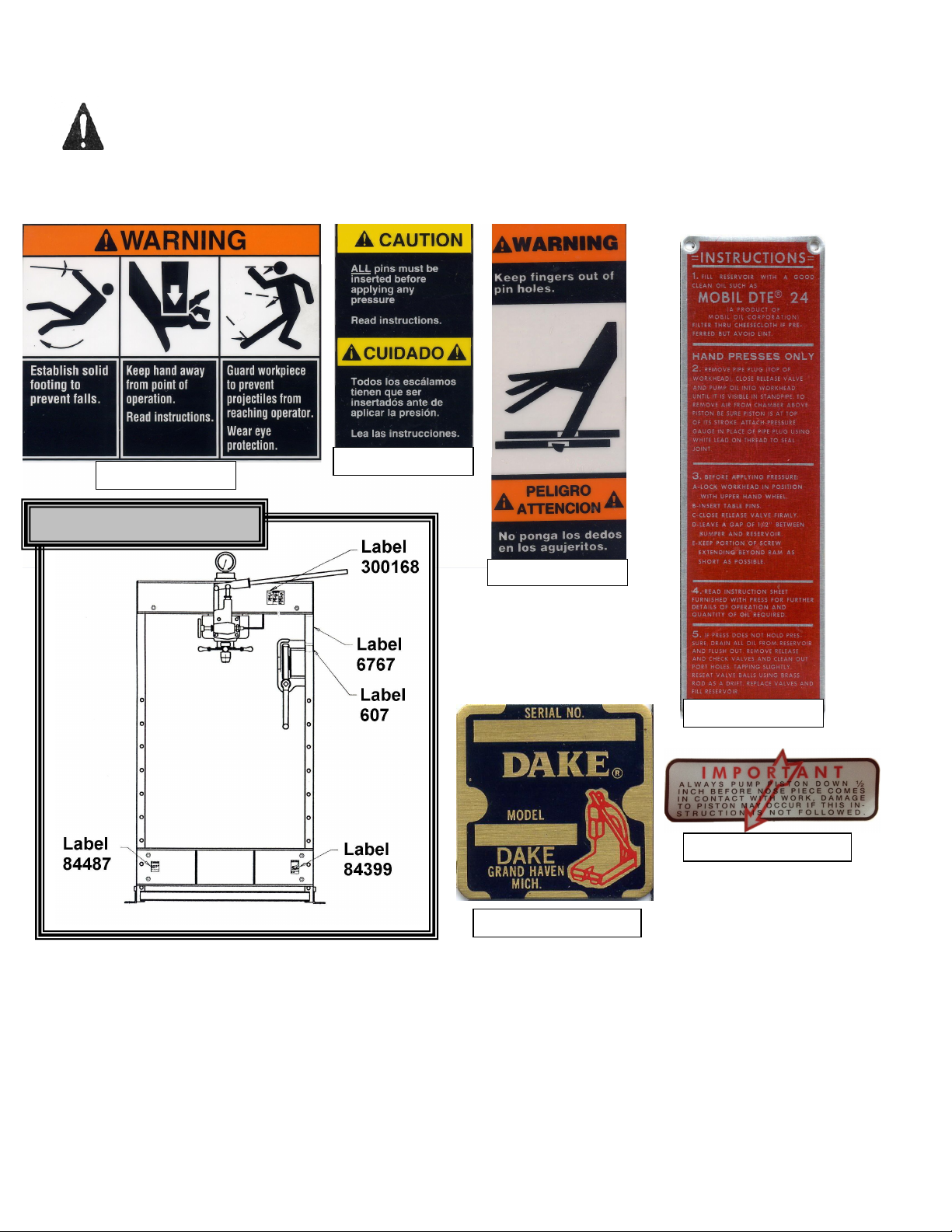
WARNING LABELS
Label 300168
Label 84487
Label 84399
Label 6767
Label 607
Label 634
To the left is the safety Alert symbol. When you see these safety alert symbols on your press, be
alert to the potential for personal injury.
Follow recommended precautions and safe operating practices.
Carefully read all safety messages in these instructions and on your press safety signs.
Keep safety labels in good condition. Replace missing or damaged safety labels. This machine is
intended to be operated by one person. This person should be conscious of the press ram movement not
only for himself but also for persons in the immediate area of the machine.
Label Placement View
Additional warnings
Employer is responsible to perform a hazard/PPE assessment before work activity.
Do not make repairs or adjustments to any hydraulic system unless you are competent or working
under competent supervision. If in doubt consult a qualified technician or engineer
Only use Dake original parts
Do not alter this press from the original design.
Tag out procedures must be followed by authorized employees as per OSHA.
25H Press 10/2015
Page 4

4
* Note: If press leaks around the ram but holds pressure the reservoir has been overfilled.
HYDRAULIC – Relieve all hydraulic pressure before servicing press. Turn the red release handle to relieve
pressure.
SPRING PRESSURE – Clamp ring on bottom of piston must be in place before removing cylinder.
GRAVITY – Hoist & table channel. Always place table pins under the table channels first then install remaining
pins. Always release pressure on the cable before using press.
TROUBLE SHOOTING – DAKE HAND HYDRAULIC PRESSES
PUMP PACKING LEAKAGE
If oil leaks past the pump packing, tighten the pump packing nut (551) until pump handle works hard, then
slack off just enough to cause the handle to stay in position by itself. After long periods of operation, it may be
necessary to install new pump packings.
LUBRICATION
Keep all working parts of the press well oiled for easier operation. Also keep a light film of oil over the entire
surface of the ram to prevent rust.
IF PRESS DOES NOT HOLD PRESSURE
This condition is nearly always caused by dirt under pressure ball valve part number (586). See workhead
assembly drawing. To remedy this condition, first remove the reservoir drain plug and drain off all the oil in the
reservoir. Next, remove parts, 3/8” pipe plug (588), check valve spring (579) and valve ball (586) then clean
out port hole and valve seat thoroughly. Replace and using a small piece of brass rod as a drift, tap the brass
rod lightly to seat the ball properly. Replace spring and plug using extreme care to prevent dirt from entering.
Replace the drain plug and refill the reservoir with clean filtered oil.
If above procedure does not correct the condition, air may be present in the chamber above the piston and
should be removed as directed in Filling Press with Oil paragraph III.
SYMPTOM CAUSE SOLUTION
Oil leaking from
piston oil seal.
Press will not hold
pressure.
Press will not build
rated tonnage.
Oil leaking from
pump plunger
Oil leaking from
release valve rod
Pump handle drifts
up.
Ram will not return. Return Spring damaged.
1) Reservoir is over filled. *
2) Piston Packing is worn or damaged.
1) Check Ball is contaminated.
2) Ball and Seat have poor contact.
3) Piston Packing is worn or damaged.
1) Pump Plunger Leather is worn or
damaged.
2) See 1,2,3 Above.
3) Gauge is defective.
1) Packing Nut Loose.
2) Worn Packings.
1) Valve Rod Packing Nut is Loose
2) Packings are worn.
Defective Check Ball or Check Ball
Spring.
Piston is bent or damaged.
Piston Packing is defective.
1) Drain excess oil.
2) Replace Piston Packing.
1) Remove and clean Check
Balls and Seats.
2) Reseat Ball on Seat.
3) Replace Piston Packing.
1) Replace Pump Plunger
leather.
2) See 1,2,3 Above.
3) Replace Gauge.
1) Tighten Packing Nut.
2) Replace packings.
1) Tighten Packing Nut.
2) Replace Packings.
Clean Check Ball, Reseat.
Replace Spring.
Replace Spring.
Replace Piston.
Replace Piston Packing.
25H Press 10/2015
Page 5

5
HANDPUMP ASSEMBLY
Part
Hand Pump Assembly Complete
700887
Repair Kit
– Cylinder & Hand Pump Assembly
Item Qty Description
No.
1 1 Pump Body 546
2 3 Ball valve ½” Dia. 586
3 1 ¼“-20 x ½“ Nylock Hex Cap Screw 28297
4 1 Washer #12 Flat 43629
5 1 Pump Plunger Leather 599
6 1 Check Valve Spring 579
7 1 Fitting, Tube, Poly-Tite 71413
8 7 Pump Packing 573
9 1 Pump Packing Nut 551
10 1 Handle Socket 550
11 1 Handle Socket Link 555
12 6 3/8” Retaining Rings 43972
13 1 Pump Plunger 554
14 3 Handle Socket Pin 594
15 1 Valve Rod 1129
16 1 Valve Rod Packing Nut 576
17 8 Valve Rod Packing 987
18 1 3/8” Pipe Plug 588
19 1 3/8”-16 x 5/8” Set Screw 43589
20 1 Pump Gasket 591
(Includes items – 5,8,17,20,21,23,30,31)
25H Press 10/2015
701290
Page 6

6
Part
Repair Kit
– Cylinder & Hand Pump Assembly
WORKHEAD ASSEMBLY
Item Qty Description
21 1 Cylinder Gasket 998
22 1 Cylinder 960
23 1 Packing Ring (Serial No. > 192522) 17976
24 & 25 1 Piston Assembly (Serial No. < 192522) 701800
1 Piston Assembly (Serial No. > 192523) 716221
26 1 Ram Spring 968
27 1 1/2” Pipe Plug 596
28 1 1/2” Street Elbow 590
29 1 1/8” Pipe Plug 589
30 1 Oil Seal 999
31 1 Piston Bumper 996
32 2 Clamp Ring 982M
33 1 Screw Adjusting Wheel 716518
34 1 Screw 971
35
36
1 Piston Leather (Serial No. < 192523)
(Used with supporting ring no. 967)
1 Screw Nose
*Thumb screw if needed 43618
1
Reservoir 963
(Includes – Items 5,8,17,20,21,23,30,31)
No.
969
986
701290
25H Press 10/2015
Page 7

7
Part
FRAME ASSEMBLY
Item Qty Description
37
38 1 ½” Tube Elbow 1252
39 1 Name Plate 81002
40 1 Air Vent Tube 632
41 1 Hand Wheel 10631
42 2 Table Plates 966
43 4 Table Pins 981
43A 4 Safety Pins 302816
44 2 Table Channel 701020
45 1 Frame 700134
46 2 Base Angles 978
47 2 Tube Fittings 1251
48 1 Tube Assembly 700133
49 1 Handle 218
50 2 Pulley 602
2 Pulley bolt 43341
2 Pulley lock washer 43645
2 Pulley nut 43912
51 9” Tube, ¼” Plastic 67761
52 2 Fitting, Tube, Poly-Tite 71413
53 2 Spacer 997
54 1 Cable 988
55 4 Cable Clamps 991
56
N/A 4 Channel Washers 25H138P
N/A 4 Wkhd mounting bolts 43348
1 1 Gauge
Bushing
4 Table Spacer Assembly
one each of washer,
bolt, spacer per part #
No.
71265
81384
716691
25H Press 10/2015
Page 8

8
TABLE HOIST
Part
Complete Table Hoist Assembly
700112
-S
724 Robbins Road
Item Qty Description
57
58
1 Hand Crank
Assembly
No.
1000
59 1 Worm Shaft 384
60 2 Retaining Ring 27437
61 1 Worm Key 47364
62 1 Worm 385
63 1 Hoist Frame 725
64 1 Hex Cap Screw 43335
65 1 Hex Nut 43912
66 1 Drum Shaft 724
67 1 Drum Key 737
68 1 Worm Gear 736
69 1 Cable Drum 723
70 Retaining Ring 43992
ORDERING INFORMATION
Please order all parts by number and name. Also mention model number and serial number as shown on the
plate attached to the frame of the press. Prices for parts do not include shipping charges.
Grand Haven, MI 49417
Phone: 616-842-7110 800-937-3253
Fax: 616-842-0859 800-846-3253
Web: www.dakecorp.com
E-mail: customerservice@dakecorp.com
technicalservice@dakecorp.com
25H Press 10/2015
 Loading...