

Page 1

USE AND MAINTENANCE MANUAL
AUTOMATIC BAR - FEEDING SYSTEM
FOR MOD.
SUPER TECHNICS
350 SA
THOMAS
07/2001
THOMAS S.p.A. - Via Pasubio, 32 - 36033 Isola Vicentina (VI) - Telephone 0444 / 97.61.05 - Fax 0444 / 97.69.34
Page 2

Contents
SUPER SUPER
SUPER
SUPER SUPER
TECHNICS 350 SATECHNICS 350 SA
TECHNICS 350 SA
TECHNICS 350 SATECHNICS 350 SA
Contents ........................................................................ " 2
Ordering spare parts .................................................... " 2
Guarantee ...................................................................... " 2
Machine certification and identification marking .... " 3
CHAPTER 1
Reference to accident-prevention regulations .......... " 4
1.1 - Advice for the operator ..........................................." 4
1.2 - Location of shields against accidental contact with
the tool ...................................................................." 4
1.3 - Electrical equipment according to European
Standard "CENELEC EN 60 204-1" (1992) ........... " 4
1.4 - Emergencies according to European Standard
"CENELEC EN 60 204-1" (1992) ..........................." 4
CHAPTER 2
Recommendations and advice for use ....................... " 4
2.1 - Recommendations and advice for using the machine "
4
CHAPTER 3
Technical characteristics............................................. " 5
3.1 - Table of cutting capacity and technical details ....... " 5
CHAPTER 4
Machine dimensions - Transport - Installation
Dismantling ................................................................... " 5
4.1 - Machine dimensions............................................... " 5
4.2 - Transport and handling of the machine .................." 5
4.3 - Minimum requirements for the premises
housing the machine .............................................." 5
4.4 - Anchoring the machine........................................... " 5
4.5 - Allineamento caricatore .......................................... " 5
4.6 - Instructions for electrical connection ......................" 6
4.7 - Instructions for assembly of the loose parts and
accessories ............................................................." 6
4.8 - Disactivating the machine ....................................... " 6
4.9 - Dismantling ............................................................." 6
CHAPTER 5
Machine functional parts ............................................. " 6
5.1 - Operating head....................................................... " 6
5.2 - Vice ........................................................................." 6
5.3 - Bed.........................................................................." 7
CHAPTER 6
Description of the operating cycle ............................. " 8
6.1 - Starting up and cutting cycle .................................. " 8
CHAPTER 7
Ordering spare parts
- When ordering spare parts you must state:
MACHINE MODEL
SERIAL NUMBER
PART REFERENCE NUMBER
Without these references WE WILL NOT SUPPLY the spares. See point 10.1 - list of spare parts -.
Regulating the machine ............................................... " 9
7.1 - Cutting head ..........................................................." 9
7.2 - Vice ........................................................................." 9
7.3 - Head return stroke limiting device .........................." 10
7.4 - Restoring oil level in head compensation cylinder
tank ........................................................................." 10
7.5 - Piece counter.......................................................... " 10
7.6 - Feed repeater ........................................................." 1 1
7.5 - Adjustment of pneumatic system pressure............ " 11
7.6 - Adjustment of cutting length................................... " 11
7.7 - Decimal lenght adjustment ....................................."11
7.8 - Adjustment of feeding system ................................ " 11
7.9 - Regulating arm blockage........................................ " 12
7.10-Changing the disk ..................................................." 1 2
7.11-Clutch adjustment ................................................... " 12
CHAPTER 8
Routine and special maintenance .............................. " 13
8.1 - Daily maintenance .................................................. " 13
8.2 - Weekly maintenance .............................................. " 13
8.3 - Monthly maintenance ............................................. " 13
8.4 - Six-monthly maintenance ....................................... " 13
8.5 - Oils for lubricating coolant ......................................" 14
8.6 - Oil disposal ............................................................. " 14
8.7 - Special maintenance .............................................." 14
CHAPTER 9
Material classification and choice of tool .................. " 14
9.1 - Definition of materials ............................................." 14
9.2 - Choosing the disk ................................................... " 14
9.3 - Teeth pitch .............................................................. " 15
9.4 - Cutting and advance speed...................................." 15
9.5 - Running in the disk ................................................." 15
9.6 - Disk structure .......................................................... " 15
9.7 - Type of disks ..........................................................." 1 5
Tooth shape ........................................................... " 15
Tooth cutting angle ................................................. " 15
9.7.1 - Table of recommended cutting parameters ................. " 16
9.7.2 - Table of cutting speed according to disk diameter........ " 16
CHAPTER 10
Machine components ................................................... " 1 7
10.1- List of spare parts .................................................. " 17
CHAPTER 11
Wiring diagrams ........................................................... " 26
CHAPTER 12
Troubleshooting............................................................ " 31
12.1-Blade and cutting diagnosis.................................... " 31
CHAPTER 13
Noise tests ..................................................................... " 33
Plates and labels .......................................................... " 33
Guarantee
- The Company guarantees that the machine to which this manual refers has been designed and built to comply with safety regulations
and that it has been tested for functionality in the factory.
- The machine is guaranteed for 12 months: the guarantee does not cover the electric motors, electric components, pneumatic
components or any damage due to dropping or to bad machine management, the failure to observe maintenance standards or bad
handling by the operator.
- The buyer has only the right to replacement of the faulty parts, while transport and packing costs are at his expense.
- The serial number on the machine is a primary reference for the guarantee, for after-sales assistance and for identifying the machine
for any necessity.
2
Page 3

SUPER SUPER
SUPER
SUPER SUPER
TECHNICS 350 SATECHNICS 350 SA
TECHNICS 350 SA
TECHNICS 350 SATECHNICS 350 SA
Machine certification and identification marking
MACHINE LABEL
via Pasubio, 32 36033 ISOLA VIC. - ITALIA
MODEL
TYP
SERIAL NUMBER
YEAR OF MANUFACTURE
SUPER TECHNICS 350
(Space reserved for the NAME and STAMP of the DEALER and/or IMPORTER)
3
Page 4
SUPER SUPER
SUPER
SUPER SUPER
TECHNICS 350 SATECHNICS 350 SA
TECHNICS 350 SA
TECHNICS 350 SATECHNICS 350 SA
REFERENCE TO ACCIDENT-
1
PREVENTION REGULA TIONS
This machine has been built to comply with the national and
community accident-prevention regulations in force.
Improper use and/or tampering with the safety devices will
relieve the manufacturer of all responsibility.
1.1 - Advice for the operator
- Check that the voltage indicated on the plate, normally fixed
to the machine motor, is the same as the line voltage.
- Check the efficiency of your electric supply and earthing system;
connect the power cable of the machine to the socket and the
earth lead (yellow-green in colour) to the earthing system.
- When the tool head is in rest position (raised), the toothed
disk must be stationary.
- It is forbidden to work on the machine without its shields (these
are all white, blue or grey in colour).
- Always disconnect the machine from the power socket before
changing the disk or carrying out any maintenance job, even
in the case of abnormal machine operation.
- Always wear suitable eye protection.
- Never put your hands or ar ms into the cutting area while the
machine is operating.
- Do not shift the machine while it is cutting.
- Do not wear loose clothing with sleeves that are too long,
gloves that are too big, bracelets, chains or any other object
that could get caught in the machine during operation; tie back
long hair.
- Keep the area free of equipment, tools or any other object.
- Perfor m only one operation at a time and never have several
objects in your hands at the same time. Keep your hands as
clean as possible.
- All internal and/or internal operations, maintenance or repairs,
must be performed in a well-lit area or where there is sufficient
light from extra sources so as to avoid the r isk of even slight
accidents.
overload, protection is provided by a thermal probe.
- In the event of a power cut, the specific start-up button must
be reset.
- The machine has been tested in conformity with point 20 of
EN 60204.
1.4 - Emergencies according to European
Standard "CENELEC EN 60 204-1"
- In the event of incorrect operation or of danger conditions, the
machine may be stopped immediately by pressing the red
mushroom button.
NOTE: Resetting of machine operation after each emergency
stop is achieved by reactivating the specific restar t
button.
RECOMMENDATIONS AND
2
AD VICE FOR USE
2.1 - Recommendations and advice for using the
machine
- The machine has been designed to cut metal building
materials, with different shapes and profiles, used in
workshops, turner’s shops and general mechanical structural
work.
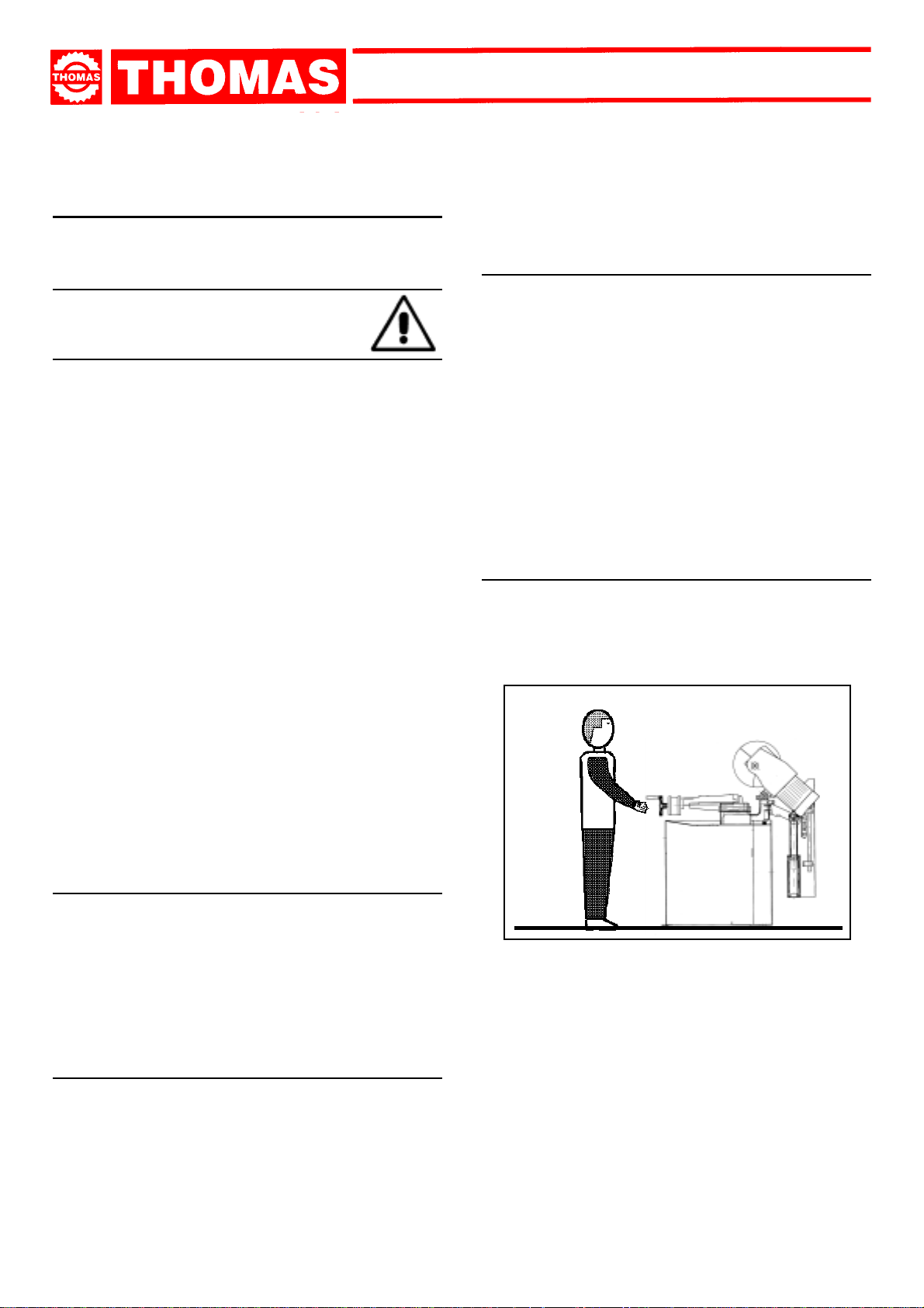
- Only one operator is needed to use the machine.
1.2 - Location of shields against accidental
contact with the tool
- Grey metal shield screwed onto the disk head.
- Self-regulating mobile blue aluminium shield, fitted coaxially
with the fixed shield.
- Blue metal protection on the feeeding system.
1.3 - Electrical equipment according to European
Standard"CENELEC EN 60 204-1" which assimilates, with some integrating modifications,
the publication "IEC 204-1 "
- The electrical equipment ensures protection against electric
shock as a result of direct or indirect contact. The active parts
of this equipment are housed in a box to which access is limited
by screws that can only be removed with a special tool; the
parts are fed with alternating current at low voltage (24 V).
The equipment is protected against splashes of water and
dust.
- Protection of the system against short circuits is ensured by
means of rapid fuses and earthing; in the event of motor
4
- To obtain good running-in of the machine it is advisable to
start using it at intervals of about half an hour. This operation
should be repeated two or three times, after which the machine
may be used continuously.
- Before starting each cutting operation, ensure that the part is
firmly gripped in the vice and that the end is suitably supported.
- Do not use disks of a different size from those stated in the
machine specifications.
- If the disk gets stuck in the cut, release the running button
immediately, switch off the machine, open the vice slowly,
remove the part and check that the disk or its teeth are not
broken. If they are broken, change the tool.
- Before carrying out any repairs on the machine, consult the
dealer or apply to THOMAS.
Page 5
TECHNICAL
3
CHARACTERISTICS
3.1 -
Table of cutting capacity and technical details
CUTTING
CA PACI TA ` DI
TAGLIO
CAPACITY
90° 60 120 105x105 160x90
45° DX - SX 60 100 85 x85 85x70
SUPER SUPER
SUPER
SUPER SUPER
TECHNICS 350 SATECHNICS 350 SA
TECHNICS 350 SA
TECHNICS 350 SATECHNICS 350 SA
2300
1450
2-speed three-phase electric motor KW 1,35 - 1,7
Oil-bath reduction unit i 32 : 1
Max. blade diameter mm 350
Blade rotation speed rpm 22 - 44- 88
Vice opening mm 170
Machine Weight KG 220
Coolant liquid L 5
Working table height with base mm 940
MACHINE DIMENSIONS
TRANSPORT
4
INST ALLATION
DISMANTLING
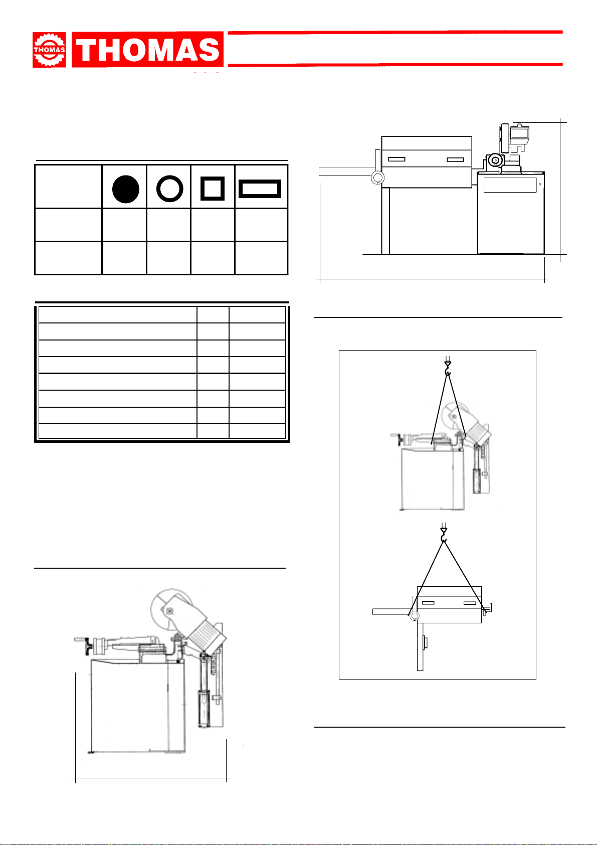
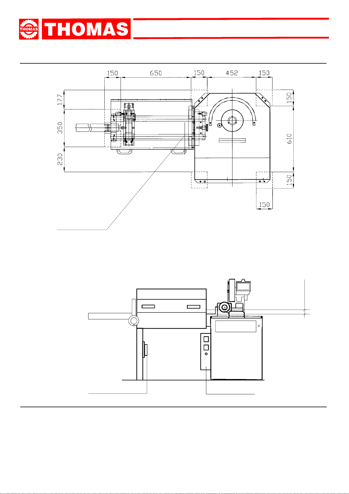
4.1 - Machine dimensions
4.2 - Transport and handling of the machine
If the machine has to be shifted use a fork-lift truck or sling it
with straps as illustrated.
1400
4.3 - Minimum requirements for the premises
housing the machine
- Mains voltage and frequency complying with the machine motor
characteristics.
- Environment temperature from -10 °C to +50 °C.
- Relative humidity not over 90%.
5
Page 6
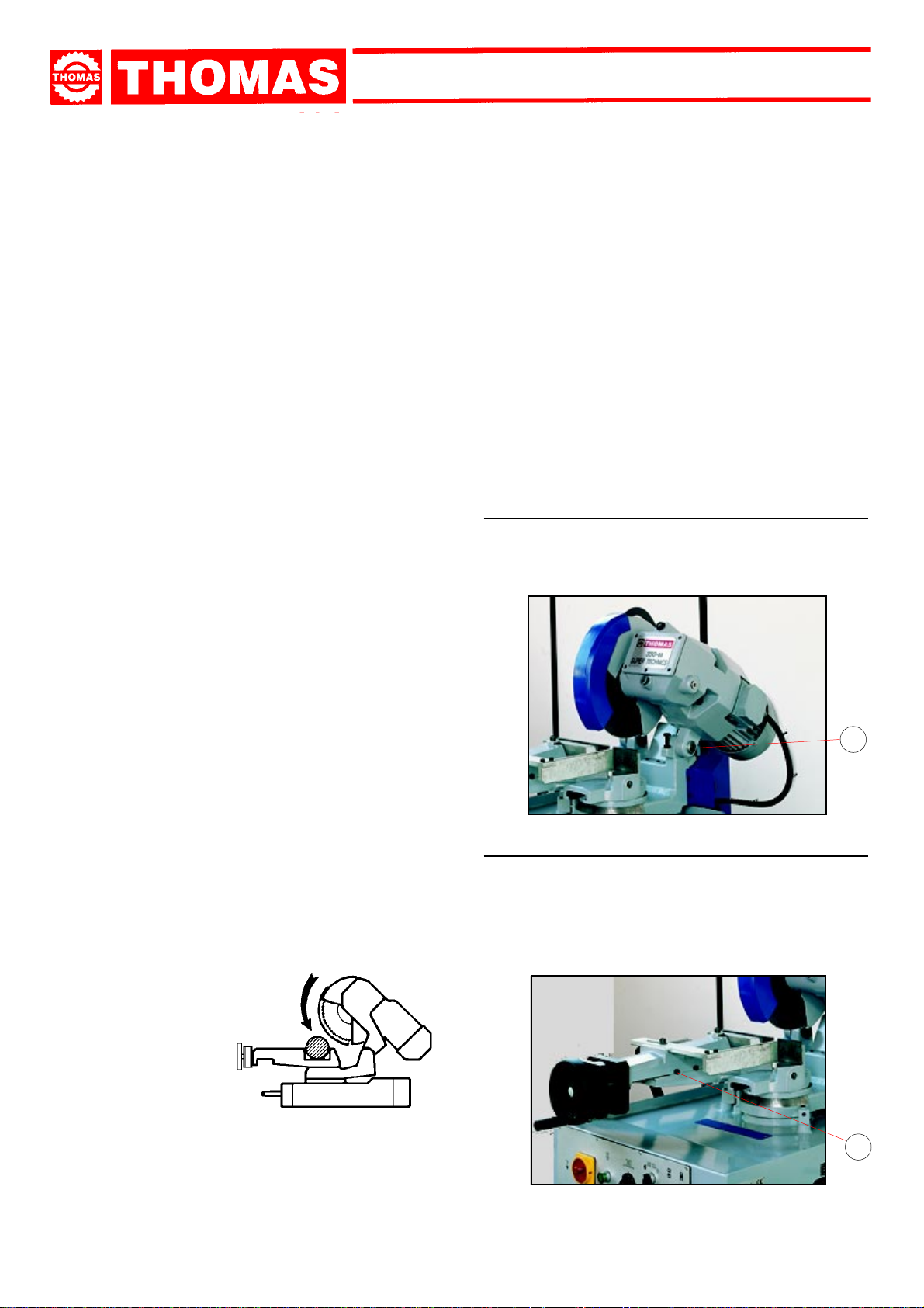
4.4 - Anchoring the machine
B
à
à
A
SUPER SUPER
SUPER
SUPER SUPER
TECHNICS 350 SATECHNICS 350 SA
TECHNICS 350 SA
TECHNICS 350 SATECHNICS 350 SA
POS. A
POS. B
- Position the machine on a firm cement floor, maintaining, at the rear, a minimum distance of 1000 mm from the wall; anchor it to the
ground as shown in the diagram, using screws and expansion plugs or tie rods sunk in cement, ensuring that it is sitting level.
- Adjust with a calibrated bar the level between the machine vice bed and the input roller by means of the screws located on the
supporting leg of the feeding system. The feeding system level should be 0.1- 0.2mm higher than the machine vice bed.
à
0,1-0,2 mm
PNEUMATIC VALVE
4.5 - Feeding system alignment
- The feeding system can be mounted to the machine base in two different positions:
POSITION A : allows mitre cutting 45° right and left. This is the position recommended to cut solid and shapes material up to 60
mm diameter.
POSITION B : allows rectangle cutting up to 160x90mm. (max.)
ATTENTION: make sure that the material supporting rollers are correctly aligned to the machine working table level.
6
ELECTRIC BOX
Page 7

SUPER SUPER
SUPER
SUPER SUPER
TECHNICS 350 SATECHNICS 350 SA
TECHNICS 350 SA
TECHNICS 350 SATECHNICS 350 SA
4.6 - Instructions for electrical connection
- The machine is not provided with an electric plug, so the
customer must fit a suitable one for his o wn working conditions:
1 - WIRING DIAGRAM FOR 4 -WIRE SYSTEM FOR THREE-
PHASE MACHINE - SOCKET FOR A 16A PLUG
R = L1
S = L2
T = L3
PE = GND
4.7 - Instructions for assembly of the loose parts
and accessories
Fit the components supplied:
- part. 1 Fit the feeding system
4.8 - Disactivating the machine
- If the sawing machine is to be out of use for a long period, it is
advisable to proceed as follows:
1) detach the plug from the electr ic supply panel
2) empty the coolant tank
3) carefully clean and grease the machine
4) if necessar y, cover the machine.
MACHINE FUNCTIONAL
5
PARTS
5.1 - Operating head
- Machine part composed of the parts that transmit movement
(motor, reduction unit).
5.2 - Machine bed and Vice
- Support structure for the OPERATING HEAD (rotating ar m
for gradual cutting, with respectiv e bloc king system), the VICE,
and the housing for the cutting coolant TANK.
- System for gripping material during the cutting operation, by
means of the approach handwheel and pneumatic locking.
It is provided with an anti-burr de vice for blocking the part that
is to be cut.
4.9 - Dismantling
(because of deterioration and/or obsolescence)
General rules
If the machine is to be permanently demolished and/or scrapped,
divide the material to be disposed of according to type and
composition, as follows:
1) Cast iron or ferrous materials, composed of
secondary raw materials, so they may be taken to an iron
foundry for re-smelting after having removed the contents
(classified in point 3);
2) electrical components, including the cable and electronic material (magnetic cards, etc.), fall within the category of material
classified as being assimilable to urban waste according
to the laws of the European community, so they may be set
aside for collection by the public waste disposal service;
3) old mineral and synthetic and/or mixed oils, emulsified oils
and greases are special refuse, so they must be collected,
transported and subsequently disposed of by the old oil
disposal service.
NOTE: since standards and legislation concerning refuse in
general is in a state of continuous evolution and theref ore
subject to changes and variations, the user must keep
informed of the regulations in force at the time of
disposing of the machine tool, as these may differ from
those described above, which are to be considered as
a general guide line.
metal alone, are
5.3 - Material feeding system
- Pneumatic device for material feeding.
7
Page 8
SUPER SUPER
SUPER
SUPER SUPER
TECHNICS 350 SATECHNICS 350 SA
TECHNICS 350 SA
TECHNICS 350 SATECHNICS 350 SA
DESCRIPTION OF THE
6
OPERATING CYCLE
Before operating, all the main organs of the machine must be set in optimum conditions (see the chapter on “Regulating the
machine”).
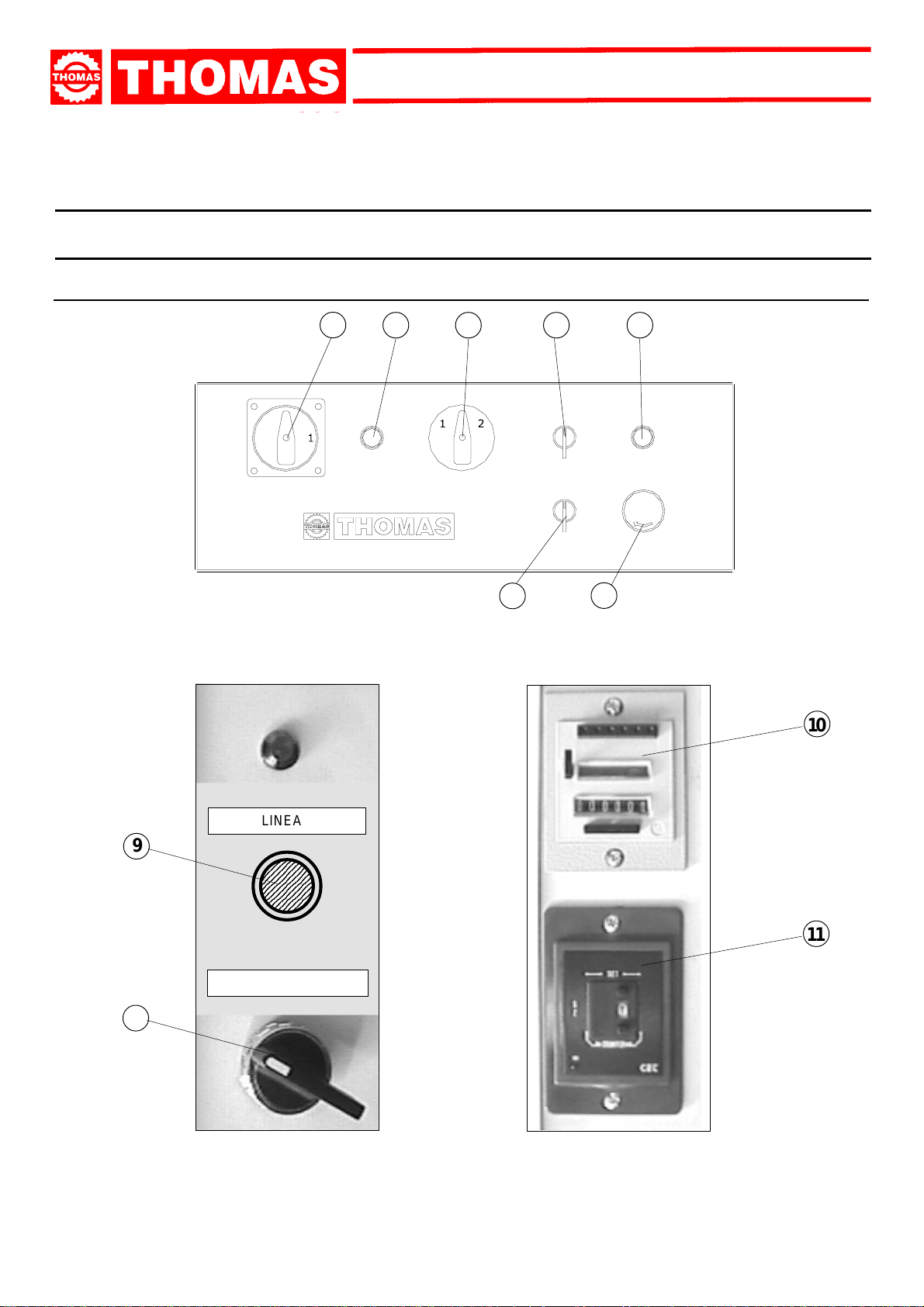
6.1 - Starting up and cutting cycle
3
2 4 5 6
17
10
LINEA
9
11
MAN. AUTOM.
8
8
Page 9
SUPER SUPER
SUPER
SUPER SUPER
TECHNICS 350 SATECHNICS 350 SA
TECHNICS 350 SA
TECHNICS 350 SATECHNICS 350 SA
CUTTING CYCLE:
- Vice locking;
- Head downfeed;
- Head lifting;
- Vice opening;
- Material feeding.
- Ensure that the machine is not in emergency stop condition; if
it is, release the red mushroom button ( 1 ).
- Make sure that the connection to the pneumatic system has
been carried our according to the chapter 7 paragraph 7.7.
- Ensure that the selector ( 8 ) is in "MANUAL" mode.
- Turn the main switch ( 3 ) in position ON.
- Press the start/reset button ( 2 ): its green light will go on.
- Select the cutting speed on the switch ( 4 ):
position 1 = 22 rpm
position 2 = 44 rpm
- Set the number of pieces to be cut on the piece-counter (10)
(see chapter 7 paragraph 7.5).
- Set the number of feed repetition on the feed repeater (11)
just in case the cutting length required is longer than the
mechanical stroke of the feeding system (see chapter 7
paragraph 7.6). Note: set “1” if no feed repetition is required.
- Place material to be cut in the vice. Close jaws against
piece,keeping a distance of approx. 3 - 4 mm.
- Adjust the cutting stroke by means of the selector ( 5 )
approaching the blade upto 10 mm from the workpiece. Position
the relevant mechanical endstroke.
- Set the required cutting length (
- Adjust the vice of the feeding system (
7.10
).
- Set the blade downfeed speed on the regulatorì according to
the specifications of the workpiece.
- Press Cycle Start and verify the following functions:
vice clamping, blade rotation anticlockwise, coolant liquid flow
and cutting cycle execution.
Turn the selector ( 8 ) to the "AUTOMATIC" mode while the
machine is performing the initial cutting cycle end press the
push button ( 9 ) . The machine will feed the material to the
preset cutting length.
- The machine will go on performing more cutting cycles as
long as the material to be cut is finished.
see chapter 7 para. 7. 8
see chapter 7 para.
).
- When starting to cut with a new disk, in order to safeguar d
its life and efficiency, the first two or three cuts must be
made while exerting a slight pressure on the part, so that
the time taken to cut is about double the normal time (see
below in the chapter on “Material classification and choice
of disks” in the section on
- Press the red emergency button ( 1 ) when there are conditions
of danger or malfunctions in general, so as to stop machine
operation immediately.
Running in the disk
).
REGULATING
THE
7
MACHINE
7.1 - Cutting head
- If excessive axial pla y is found on the hinge , it will be sufficient
to tighten the ring nuts ( A ), paying attention not to make the
joint too tight.
A
7.2 - Vice
- In case of wrong operation press Emergency Push-button
( 1 ).
CUTTING DIRECTION
The cropper is now ready to start work, bearing in mind that the
CUTTING SPEED and the TYPE of DISC - combined with a
suitable descent of the head - are of decisive importance for
cutting quality and for machine performance (for further details
on this topic, see below in the chapter on “Material classification
and choice of disks”).
- The device does not require any particular adjustment; in the
event of e xcessive pla y in the sliding guide, tighten the dowels
( B ) for adjusting the gib inside the slide.
- Approach the vice jaw upto 4-5mm from the material to be
cut.
B
9
Page 10
SUPER SUPER
SUPER
SUPER SUPER
TECHNICS 350 SATECHNICS 350 SA
TECHNICS 350 SA
TECHNICS 350 SATECHNICS 350 SA
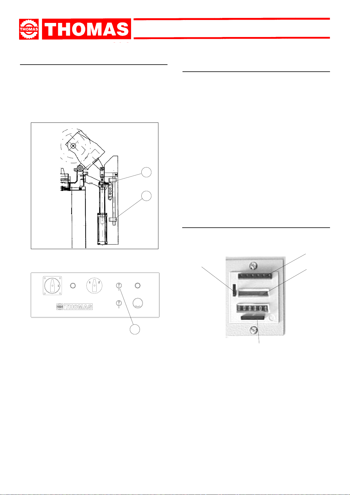
7.3 - Head return stroke limiting device
It consists in a mechanical adjustment system, mounted parallel to the head rise cylinder, to reduce the passive phases of the
operating cycle, in other words to eliminate the idle stroke that
takes place when the size of the part to be cut is much smaller
than the maximum cutting capacity. Practically, you adjust the
starting position of the disk in proximity of the part, independently
of its dimensions.
8
9
7.4 - Restoring oil level in motorhead compensation cylinder tank
- Braking fluid in the cylinder controlling the head, may consume
through the time.
- It is therefore important to restore the oil quantity inside the
compensation tank by removing the plug and then using a
syringe type injector to fill the tank.
- First, take the head to the upper position and disconnect
airs upply from the pneumatic system (disconnect the air
pipe from the machine). Switch on the machine and push
the Line button.
- Add oil making sure that the selector ( 5 ) is switched to the
right (head downfeed).
- Add oil until the rod, corresponding to the second mark on the
stem, has come out completely.
- Air must be bleeded from the tank by loosening the screw
located on the side of the cylinder (see arrow) until some oil
pours out (always keep the selector ( 5 ) to the right); when
this has been done, secure the screw, remove the injector
and put back the plug.
- Connect the machine to the pneumatic system.
- Use SHELL hydraulic oil 32 or similar.
7.5 - Piece-Counter
5
To carry out this operation you must:
- slightly open regulator.
- Rotate the selector ( 5 ) either to the right or left to lower or lift
the motorhead.
- position and secure the mechanical stop ( 8 ) against upper
plate of the cylinder, so as to press the upper limit micros witch.
- the lower limit switch ( 9 ) is set during inspection and limits the lower stroke of the motorhead. Do not change this
setting.
ATTENTION:
- It is not necessary to adjust the upper end-stroke everytime;
one can bring the disk near to the workpiece by means of
selector ( 5 ) and then start the automatic cutting cycle
wich will take place from the actual position of the disk.
Do notice that, once the cut is completed, the motorhead
will go to the upper end-stroke ( against the relevant
microswitch ).
- operate on regulator to modify motorhead return speed.
- Press Reset (A) and hold to release the Lever (B).
D
B
C
A
- Move the Lever (B) to the direction shown by the arrow and
leave it in this position. Release the Reset button (A). Now
the numbers appear on the window (C).
- Hold the Lever (B) and set the number required by pressing
the keys (D) starting from the left operating the two keys at
the same time.
- As soon as you set the first figure, you can go on towards the
right with more figures. On the surface of each key there is a
grooved area to set a single figure by means of a pencil.
- Release the Lever (B) as soon as the setting is completed.
10
Page 11
7.6 - Feed repeater
- You can set the number of feed repetition on the feed repeater
just in case the cutting length required is longer than the
mechanical stroke of the feeding system.
Set “1” if no feed repetition is required.
- Take into account the blade thickness and set the mechanical
stroke of the feeding system accordingly.
For example:
In case you need 1500mm cutting length
SUPER SUPER
SUPER
SUPER SUPER
A
TECHNICS 350 SATECHNICS 350 SA
TECHNICS 350 SA
TECHNICS 350 SATECHNICS 350 SA
B
1500 - 6
3
1500 = cutting lenght.
6 = blade thichness ( 3 x 2 )
3 = number of required feeding runs
498 = this is lenght the feeding stroke must be set to on the
metric scale .
= 498
7.7 - Adjustment of pneumatic system pressure
- The pressure in the pneumatic system necessary for the proper
operation of the sawing machine must be equal to 6 - 7 Bar.
- Check on pressure switch (11) the exact correspondence and
if necessary operate on regulator (12) to set the ideal pressure.
- Make sure that a drop of oil runs through the lubricator bulb
( 13 ) every 4/5 work cycle.
- Set the regulators A = forward
to absorbe the mechanical stop of the feeding system
during the cutting cycle.
I = backward
I
A
12
11
13
7.8 - Adjustment of cutting length
- Proceed as follows to adjust the cutting length:
- Loose screw ( A ).
- Turn handwheel ( B ) to set the required cutting lentgh on the
metric scale.
- Lock screw ( A ).
7.9 - Decimal adjustment
- This is a fine cutting length adjustment by means of a Vernier
(14).
- Release the screw (15) and turn the vernier as much as you
need with reference to the engraved marks.
- One mark is 0.05mm (metric system).
- One mark is 1/500 of a inch (English system)
- Lock the screw (15).
14
15
11
Page 12

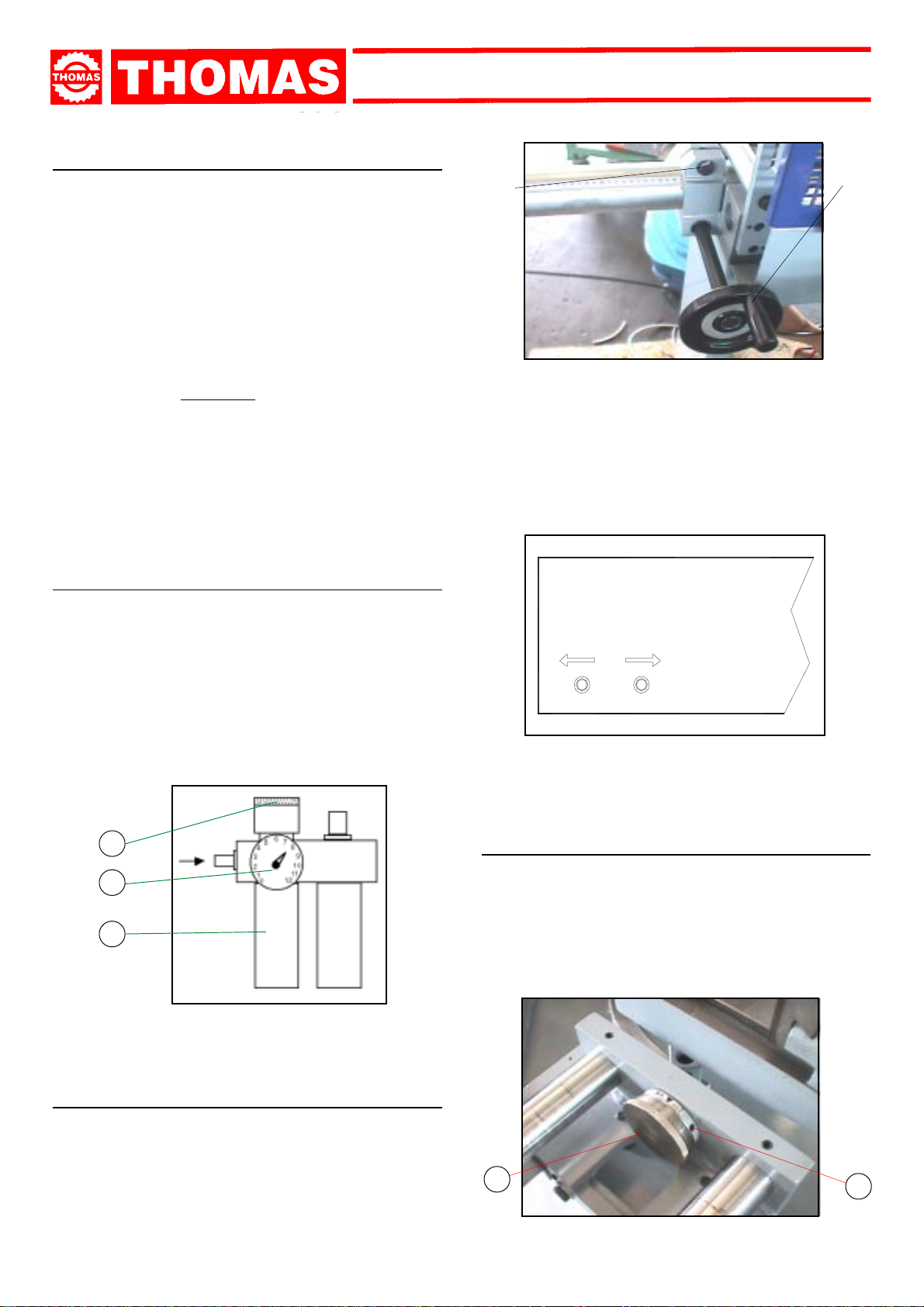
7.10 - Adjusting the feeding system
- Adjust the feeding vices as follows:
- Load the workpiece and clamp it in the bench vice by means
of the relevant handwheel.
- Loose the vice screw ( C ), approach the relevant jaw upto 4-
5 mm from the material to be cut. Tight the screw.
- Loose the vice screw ( D ), approach the relevant jaw upto
0,5 mm from the material to be cut. Tight the screw.
NOTE: carefully adjust the vices ( C ) and ( D ). On the
contrary, the microswitch controlling the presence of the
workpiece will stop the machine.
- Loose the bench vice allowing 4-5mm clearance from the vice
jaw and the workpiece.
SUPER SUPER
SUPER
SUPER SUPER
BEFORE PERFORMING THE FOLLOWING OPERATIONS,
THE ELECTRIC POWER SUPPLY AND THE POWER CABLE
MUST BE COMPLETELY DISCONNECTED.
TECHNICS 350 SATECHNICS 350 SA
TECHNICS 350 SA
TECHNICS 350 SATECHNICS 350 SA
7.12 - Changing the disk
To change the disk:
- Release the mobile yellow, white or orange guard and tur n it
back.
- Block a piece of wood in the vice and lean the disk on it.
- Insert the special spanner provided and remove the screw
( 1 ), slackening it in a clockwise direction because it has a
left-handed thread, then slip off the flange that holds the disk.
- Fit the new disk, checking the cutting direction of the teeth,
then replace the flange, the screw and the mobile white, y ellow
or orange guard.
D
C
7.11 - Regulating arm blockage
- If there is insufficient blockage of the head arm in the desired
position, slacken the screw ( 1 ) on the lever, hold the bush
( 2 ) in position, turn the lever to the left and tighten the screw.
1
7.13 - Clutch adjustment
Inside the head there is a clutch device which has already been
adjusted during assembly. If, after long use, further adjustment
is necessary, proceed as follows:
- remove the cover
- fit the template provided
- turn the motor shaft so that the ring nut ( 1 ) is in a convenient
position to allow it to be tightened or slackened enough to
calibrate the clutch system.
12
2
1
ANY REPLACEMENTS OF OTHER PARTS - SUCH AS THE
COMPONENTS OF THE REDUCTION GEAR, MOTOR AND
VARIOUS ELECTRIC PARTS - MUST BE CARRIED OUT BY
SKILLED OR COMPETENT PERSONNEL.
1
Page 13

SUPER SUPER
SUPER
SUPER SUPER
TECHNICS 350 SATECHNICS 350 SA
TECHNICS 350 SA
TECHNICS 350 SATECHNICS 350 SA
ROUTINE
AND SPECIAL
8
MAINTENANCE
THE MAINTENANCE JOBS ARE LISTED BELOW , DIVIDED
DAILY, WEEKLY, MONTHLY AND SIX-MONTHLY
INTO
INTERVALS. IF THE FOLLOWING OPERATIONS ARE
NEGLECTED, THE RESULT WILL BE PREMATURE WEAR
OF THE MACHINE AND POOR PERFORMANCE.
8.1 - Daily maintenance
- General cleaning of the machine to remove accumulated
shavings.
- Top up the level of lubricating coolant.
- Check the disk for wear.
- Lift the head into a high position to avoid yield stress on the
return spring.
- Check functionality of the shields and emergency stops.
8.2 - Weekly maintenance
- More accurate general cleaning of the machine to remove
shavings, especially from the lubricant fluid tank.
- Clean the filter of the pump suction head and the suction
area.
- Clean and grease the screw and the sliding guide of the vice.
- Clean the disk housing.
- Sharpen the disk teeth.
1
2
8.3 - Monthly maintenance
- Check tightness of the screws on the motor, the pump, the
jaws and shields.
- Check that the shields are unbroken.
- Grease the head hinge pin.
8.4 - Six-monthly maintenance
- Change the oil in the reduction unit using oil type GEARCO
85W-140 by NATIONAL CHEMSERACH or MOBIL GLYCOLE
30 or KLUBER SINTHESO 460 EP or an equivalent oil,
proceeding as follows:
- Remove the connecting plug from the electric box and unscrew the head moving leve r.
- Drain off the old oil from the cap ( 1 ).
- Pour in new oil up to the mark ( 1 ), through the lever fixing
hole, keeping the head in upper position ( 2 ).
- Reassemble all the parts.
- Check continuity of the equipotential protection circuit
13
Page 14

SUPER SUPER
SUPER
SUPER SUPER
TECHNICS 350 SATECHNICS 350 SA
TECHNICS 350 SA
TECHNICS 350 SATECHNICS 350 SA
8.5 - Oils for lubricating coolant
Considering the vast range of products on the market, the user
can choose the one most suited to his own requirements, using
as reference the type SHELL LUTEM OIL ECO.
THE MINIMUM PERCENTAGE OF OIL DILUTED IN WATER
IS 8 - 10 %.
8.6 - Oil disposal
The disposal of these products is controlled by strict regulations.
Please see the Chapter on “Machine dimensions - Transport
- Installation” in the section on
Dismantling
.
8.7 - Special maintenance
Special maintenance operations must be carried out by skilled
personnel. Ho wever , we advise contacting THOMAS or their dealer
and/or importer. The term special maintenance also covers the
resetting of protection and safety equipment and devices.
MATERIAL
CLASSIFICATION AND
9
CHOICE OF TOOL
Since the aim is to obtain excellent cutting quality , the various
parameters such as hardness of the material, shape and
thickness, transverse cutting section of the part to be
cut, choice of the type of cutting disk, cutting speed and
control of head descent, must be suitably combined.These
specifications must therefore be harmoniously combined in
a single operating condition according to practical
considerations and common sense, so as to achieve an
optimum condition that does not require countless operations
to prepare the machine when there are many variations in
the job to be performed.The various problems that crop up
from time to time will be solved more easily if the operator
has a good knoledge of these specifications.
WE THEREFORE ADVISE YOU ALWAYS TO CHOOSE
ORIGINAL SPARE DISKS THAT GUARANTEE SUPERIOR
QUALITY AND PERFORMANCE.
9.1 - Definition of materials
The table at the foot of the page lists the characteristics of the
materials to be cut, so as to choose the right tool to use.
USE
Construction
steels
Carbon
steels
Spring steels
Alloyed steels for
hardening and
tempering and for
nitriding
Alloyed
casehardening
steels
Steel for
bearings
Tool steel
Stainless
steel
Copper alloys
Special brass
Bronze
Cast iron
TYPES OF STEEL CHARACTERISTICS
I
UNI
Fe360
Fe430
Fe510
C20
C40
C50
C60
50CrV4
60SiCr8
35CrMo4
39NiCrMo4
41CrAlMo7
18NiCrMo7
20NiCrMo2
100Cr6 100Cr6 100C6 534 A 99 52100 207 95 690÷980
52NiCrMoKU
C100KU
X210Cr13KU
58SiMo8KU
X12Cr13
X5CrNi1810
X8CrNi1910
X8CrNiMo1713
Aluminium copper alloy G-CuAl11Fe4Ni4 UNI 5275
Special manganese/silicon brass G-CuZn36Si1Pb1 UNI5038
Manganese bronze SAE43 - SAE430
Phosphor bronze G-CuSn12 UNI 7013/2a
Gray pig iron G25
Spheroidal graphite cast iron GS600
Malleable cast iron W40-05
D
DIN
St37
St44
St52
CK20
CK40
CK50
CK60
50CrV4
60SiCr7
34CrMo4
36CrNiMo4
41CrAlMo7
----
21NiCrMo2
56NiCrMoV7
C100W1
X210Cr12
----
4001
4301
----
4401
F
AF NOR
E24
E28
E36
XC20
XC42H1
----
XC55
50CV4
----
35CD4
39NCD4
40CADG12
20NCD7
20NCD2
----
----
Z200C12
Y60SC7
----
Z5CN18.09
----
Z6CDN17.12
GB
SB
---43
50
060 A 20
060 A 40
----
060 A 62
735 A 50
----
708 A 37
----
905 M 39
En 325
805 H 20
----
BS 1
BD2 - BD3
----
----
304 C 12
----
316 S 16
USA
AISI-SAE
----
----
---1020
1040
1050
1060
6150
9262
4135
9840
---4320
4315
----
S-1
D6 - D3
S5
410
304
----
316
Hardness
BRINELL
HB
116
148
180
198
198
202
202
207
224
220
228
232
232
224
244
212
252
244
202
202
202
202
220
140
120
100
212
232
222
Hardness
ROCKWELL
HRB
67
80
88
93
93
94
94
95
98
98
99
100
100
98
102
96
103
102
94
94
94
94
98
77
69
56,5
96
100
98
R=N/mm2
360÷480
430÷560
510÷660
540÷690
700÷840
760÷900
830÷980
1140÷1330
1220÷1400
780÷930
880÷1080
930÷1130
760÷1030
690÷980
800÷1030
710÷980
820÷1060
800÷1030
670÷885
590÷685
540÷685
490÷685
620÷685
375÷440
320÷410
265÷314
245
600
420
14
Page 15

SUPER SUPER
SUPER
SUPER SUPER
TECHNICS 350 SATECHNICS 350 SA
TECHNICS 350 SA
TECHNICS 350 SATECHNICS 350 SA
9.2 - Choosing the disk
First of all the pitch of the teeth must be chosen, suitable for
thematerial to be cut, according to these criteria:
- parts with a thin and/or variable section such as profiles, pipes
and plate, need close toothing, so that the number of teeth
used simultaneously in cutting is from 3 to 6;
- parts with large transverse sections and solid sections need
widely spaced toothing to allow for the greater volume of the
shavings and better tooth penetration;
- parts made of soft material or plastic (light alloys, mild bronze,
teflon, wood, etc.) also require widely spaced toothing.
9.3 - Teeth pitch
As already stated, this depends on the following factors:
- hardness of the material
- dimensions of the section
- thickness of the wall.
S (MM) PICTH SHAPE SPEED
B
shaped
C
solid
C
solid
C
solid
C
solid
C
solid
C
solid
3
3 - 2
2
2
2
1
1
S
SS
up to 2 4 - 6
2 ÷ 5 8
5 ÷ 10 8
over 10 8
up to 20 8
20 ÷ 50 10
50 ÷ 65 13 ÷
9.4 - Cutting and advance speed
The cutting speed (m/min) and the advance speed (cm2/min =
area travelled by the disk teeth when removing shavings) are
limited by the development of heat close to the tips of the teeth.
- The cutting speed is subordinate to the resistance of the
material (R = N/mm
dimensions of the widest section.
- Too high an advance speed (= disk descent) tends to cause
the disk to deviate from the ideal cutting path, producing non
rectilinear cuts on both the vertical and the horizontal plane.
2
), to its hardness (HRC) and to the
9.5 - Running in the disk
9.7 - Type of disks
The disks differ essentially in their constructive characteristics,
such as:
- Tooth shape
- Tooth cutting angle
Tooth shape
The profile of the toothing depends on the size, shape and
thickness of the section to be cut, either straight or at an angle.
It may also vary according to the pitch, but not so distinctly as to
make this an element for classification.
- Fine toothing is to be chosen for cutting small sections with a
profiled shape and tubular sections with thin walls (2-5 mm
depending on the material).
- Large toothing is suitable for cutting medium and large solid
sections or fairly thick profiled or tubular sections (o ver 5 mm).
"A" toothing:
normal fine toothing
"B" toothing:
normal large toothing with or
without shaving breaking incision
“C (HZ)” toothing:
large toothing with roughing
tooth with rake on both sides,
alternating with a finishing
tooth without rake. The roughing tooth is 0.15-0.30 mm
higher
Tooth cutting angle
Each tooth has two cutting angles:
αα
α : front rake angle
-
αα
γγ
γ : rear rake angle
-
γγ
SHARPENING CIRCULAR SAWS
"AW" toothing:
fine toothing with alternate
side rake
"BW" toothing:
large toothing with alternate
side rake
Added toothing:
disks made in this way are
used for cutting non-ferrous
metals, such as light alloys,
and plastics, and above all in
wood-working. The teeth are
hard metal (HM) plates brazed
onto the body of the disk; there
are various types and shapes
and, considering the vastness
of the field, the topic is not
developed further here.
When cutting for the first time, it is good practice to run in
the tool making a series of cuts at a low advance speed
(= 30-35 cm
to the cutting capacity and solid section of normal steel with
R = 410-510 N/mm
with lubricating coolant.
2
/min on material of average dimensions with respect
2
), generously spraying the cutting area
9.6 - Disk structure
The most commonly used disks are made of extra high speed
steel (HHS) of normal quality (HHS/DMo5) or superior quality
(HHS/Mo5 + Co5) with a treated tooth, which differentiates them
from the former on account of the high value of structural
resistance, greater resistance to seizing, absence of stress in
the mass and a better holding of lubricating coolant during work.
αα
α
αα
γγ
γ
γγ
T
3 4 5 6 7 8 9 10 12 14 16
1,3 1,6 2,1 2,5 2,9 3,4 3,8 4,2 5,1 5,9 7,2
p
1,5 2 2,5 3 3,5 4 4,5 5 6 7 8
d
h = 0,2 mm h = 0,3 mm
The rake varies especially according to the type of material
to be cut.
15
Page 16

9.7.1 - RECOMMENDED CUTTING PARAMETERS
2
2
Mild steel
R = 350-500 N/mm
Semi-hard steel
R = 500-700 N/mm
CUTTING ANGLES
*T mm
Vt m/1'
Av mm/1'
*T mm
Vt m/1'
Av mm/1'
*T mm
Vt m/1'
Av mm/1'
*T mm
Vt m/1'
Av mm/1'
*T mm
Vt m/1'
Av mm/1'
SECTION TO BE CUT (IN MM)
RECOMMENDED LUBRIFICANTS Emulsion - Cutting oil
*T mm
Vt m/1'
Av mm/1'
*T mm
Vt m/1'
Av mm/1'
2
2
Extra-hard steel
Hard steel
R = 950-1000 N/mm
R = 750-950 N/mm
Heat-treated steel
2
2
Austentic stainless
steel
R = 500-800 N/mm
Martensitic stainless
R = 950-1300 N/mm
steel
SUPER SUPER
SUPER
SUPER SUPER
2
R = 500-800 N/mm
Grey cast iron
Aluminium and alloys
Kerosene
Dry
TECHNICS 350 SATECHNICS 350 SA
TECHNICS 350 SA
TECHNICS 350 SATECHNICS 350 SA
2
2
Aluminium and alloys
R = 300-300 N/mm
R = 200-400 N/mm2Copper
Dry
R = 200-350 N/mm
Emulsion
2
2
Phosphor bronze
R = 400-600 N/mm
Hard bronze
R = 600-900 N/mm
2
2
Brass
R = 200-400 N/mm2Titanium and alloys
Alloyed brass
Cutting oil Emulsion
R = 300-800 N/mm
R = 400-700 N/mm
Tubes and beams
2
2
Tubes and beams
0,025. D
0,05. D
R = 300-600 N/mm
R = 300-600 N/mm
9.7.2 - DIAGRAM OF CUTTING SPEEDS ACCORDING TO DISK DIAMETER
Vt m/min
KEY
T Tooth pitch in millimetres
Av mm/min Advance in millimetres per minute
Vt m/min Cutting speed in metres per minute
Az Tooth advance
Ng/min Number of revs per minute
Z Number of teeth on the disk
p Tooth depth
d Diameter of the tooth fillet cone distance
h Tooth protrusion
γ Front rake
α Rear rake
N/mm Ultimate tensile stress
a-f Flat parts of the cutting edge
Ø Tube diameter or profile width
n = g/min
16
Page 17

SUPER SUPER
SUPER
SUPER SUPER
TECHNICS 350 SATECHNICS 350 SA
TECHNICS 350 SA
TECHNICS 350 SATECHNICS 350 SA
10
MACHINE COMPONENTS
10.1 - List of spare parts
REFERENCE N° DESCRIPTION
2 Revolving arm
3
4
5
6
7 Countervice
8 Mobile countervice
9 Countervice jaws
10 Burr-free jaws
11 Countervice rotation
locking pin
12
13
14
15
16
17
18 Vice jaws
19 Vice jaw washer
20 Screw M12
21 Washer
22 Screw M12
23
24
25
26
27
28
29
30
31
32 Vice gib
33 Grain M8
34 Nut M8
35 Vice thread
36 Quick lock vice spring
37 Burr-free transverse plate
38 Burr-free plate
REFERENCE N° DESCRIPTION
39
40 Screw M8
41
42
43
44
45
46
47 Oiler Ø 8
48 Grain M8
49
50
57 Extra shield
58 Spring connection
59 Head return spring
60 Nut M12
61 Screw M12
62 Head
63 3/8 gas tap
64 GUK M25x1,5 ring nut
65 Spring thrusting washer
66 Oil level and drain plug 1/2 gas
67 Hinge cylindrical pin
68 GUK M25x1,5 ring nut
69 Hinge eccentric pin
70 Eccentric bush
71 Bearing 6202
72
73
74
75 Bush
76 Bearing 32008X
17
Page 18

SUPER SUPER
SUPER
SUPER SUPER
TECHNICS 350 SATECHNICS 350 SA
TECHNICS 350 SA
TECHNICS 350 SATECHNICS 350 SA
REFERENCE N° DESCRIPTION
N° RIFERIMENTO DENOMINAZIONE
REFERENCE N° DESCRIPTION
N° RIFERIMENTO DENOMINAZIONE
77 Ring DPSM 50728
78 Cylindric pin Ø 5x12
79 Disk shaft
80 Disk
81 Disk shaft flange
82 TCCE M12x35 l.h. Screw
83 Fixed blade guard
84 Grain M8
85 Front head cover
86 Cooling distributor
87 Coolant tube
88 Grain M6
89 Mobile blade guard
90 Ring seeger Ø 60E
91 Pin
92
93 Tie rod support
94 Screw M6
95 Screw M6
96 Tie rod
97 Ring seeger Ø 10E
98 Tie rod support pin
99 Ring OR 4205
100 GUK M20x1 ring nut
101 Worm screw
102 Worm screw spacer
103 Ring seeger Ø 62I
104 Bearing 3305
105 Ring SM 32527
106 OR-Rings 4312
107 Front motor flange
108 Motor shaft (rotor)
109 Key 5x6x35
110 Washer
111 Stud bolt
112 Nut
113 Motor housing and stator
114
115 Ring OR 3081
116 Motor rear cover
117 Ring seeger Ø 25E
118 Head cover gasket
REFERENCE N° DESCRIPTION
REFERENCE N° DESCRIPTION
119 Nilos Ring 4205 AV
120 Bearing 4205
121 Motor fan
122 Fan cover
131 Clutch cone
132 Worm wheel
133 Clearance adjustment ring
134 KM8 M40x1,5 ring nut
135 Safety washer MB8
136 Cup springs 50x25 - 4x3
137 Disk shaft flange pin
140 Vice handwheel
141 Pneumatic vice cylinder
215 Cylinder head
216 Cylinder support
217 Hinge bush
218 Upper plate
219 Microswitch support plate
220 Microswitch
221 Microswitch
222 Cylinder coupling fork
223 Pin
224 Ring seeger
225 Cylinder anchoring dowel
226 Stop bar
227 Adjustable stop
228 Adjustable stop
229 Cylinder guard
230 Knob
251 Feed carriage
252 Bushing
253 Ring
254 Carriage guide gibs
255 Microswitch
256 Microswitch
257 Carriage countervice cylinder
258 Guide nut
259 Carriage countervice jaw
260 Screw
18
Page 19

REFERENCE N° DESCRIPTION
N° RIFERIMENTO DENOMINAZIONE
REFERENCE N° DESCRIPTION
N° RIFERIMENTO DENOMINAZIONE
261 Carriage vice jaw
262 Guide nut
263 Carriage vice
264 Cylinder support
265 Shaft
266 Bushing
267 Ring
268 Handwheel
269 Material feed Cylinder
270 Plate
271 Roller
272 Support
273 Roller
SUPER SUPER
SUPER
SUPER SUPER
TECHNICS 350 SATECHNICS 350 SA
TECHNICS 350 SA
TECHNICS 350 SATECHNICS 350 SA
275 Roller
276 Bearing
277 Support
278 Support
279 Vernier support flange
280 Vernier
281 Microswitch
282 Front guard
283 Rear guard
284 Hinge
285 Mobile guard
286 Handle
287 Supporting leg
288 Foot
289 Limit switch
290 Microswitch
19
Page 20

SUPER SUPER
141
140
SUPER
SUPER SUPER
TECHNICS 350 SATECHNICS 350 SA
TECHNICS 350 SA
TECHNICS 350 SATECHNICS 350 SA
20
Page 21

229
230
SUPER SUPER
SUPER
SUPER SUPER
TECHNICS 350 SATECHNICS 350 SA
TECHNICS 350 SA
TECHNICS 350 SATECHNICS 350 SA
224
223
225
226
222
227
221
218
220
219
228
215
217
216
21
Page 22

SUPER SUPER
SUPER
SUPER SUPER
TECHNICS 350 SATECHNICS 350 SA
TECHNICS 350 SA
TECHNICS 350 SATECHNICS 350 SA
22
Page 23

310 311 312 313 314 315 316
325
310 Transformer
311 Auxiliaryt contact
312 Remote control switch
313 Auxiliary relay
314 Auxiliary relay
315 Fuses cartridges
316 Head descent speed adjustment
325 Light
326 Light Push button
327 Selector
328 Piece counter
329 Feeding repeater
LINEA
SUPER SUPER
SUPER
SUPER SUPER
328
329
TECHNICS 350 SATECHNICS 350 SA
TECHNICS 350 SA
TECHNICS 350 SATECHNICS 350 SA
301 Main disconnect switch
302 Start push-button
303 Speed switch
304 Head selector
305 Cycle start push-button
306 Emergency push-button
326
327
MAN. AUTOM.
301 302 303 304 305
307
306
23
Page 24

318 Aux. relais
319 Aux. relais
320 Aux. relais
321 Aux. relais
322 Timer
323 Timer
324 Timer
SUPER SUPER
SUPER
SUPER SUPER
318 319 320 321
TECHNICS 350 SATECHNICS 350 SA
TECHNICS 350 SA
TECHNICS 350 SATECHNICS 350 SA
330 Filter
331 Vice Electrovalve
332 Head Electrovalve
333 Avance Electrovalve
334 Vice avance electrovalve
330 331 332
322 323 324
333 334
24
Page 25

SUPER SUPER
SUPER
SUPER SUPER
TECHNICS 350 SATECHNICS 350 SA
TECHNICS 350 SA
TECHNICS 350 SATECHNICS 350 SA
11
11.1 - Three-phase electric diagram
WIRING DIAGRAMS
25
Page 26

SUPER SUPER
SUPER
SUPER SUPER
TECHNICS 350 SATECHNICS 350 SA
TECHNICS 350 SA
TECHNICS 350 SATECHNICS 350 SA
26
Page 27

SUPER SUPER
SUPER
SUPER SUPER
TECHNICS 350 SATECHNICS 350 SA
TECHNICS 350 SA
TECHNICS 350 SATECHNICS 350 SA
27
Page 28

SUPER SUPER
SUPER
SUPER SUPER
TECHNICS 350 SATECHNICS 350 SA
TECHNICS 350 SA
TECHNICS 350 SATECHNICS 350 SA
28
Page 29

Main switch
Fuse holder
Fuse holder
Fuse holder
Transformer
Remote switch
Blade speed selector
Cutting head up-down selector
Automatic/Semi-automatic selector
Emergency push-button
Emergency push-button
Line push-button
Start cycle push-button
Feeding line push-button
Aux. Relay
Aux. Relay
Aux. Relay
Aux. Relay
Aux. Relay
Aux. Relay
Aux. Relay
Aux. Relay
Aux. Relay
Thermal protection
Micro-switch (low pos.)
Micro-switch (top pos.)
Micro-switch (back feed)
Micro-switch (material end)
Micro-switch (front feed)
Micro-switch (metal protection)
Electro-valve (head down)
Electro-valve (head up)
Electro-valve (vice lock)
Electro-valve (vice open)
Electro-valve (stop valve)
Electro-valve (feeding vice)
Electro-valve (feeding system)
Pilot light
Pilot light
Pilot light
Pilot light
Timer (feed vice opening gap)
Timer (feed vice departure gap)
Timer (feed vice return gap)
Piece-counter
Repeater
SUPER SUPER
SUPER
SUPER SUPER
TECHNICS 350 SATECHNICS 350 SA
TECHNICS 350 SA
TECHNICS 350 SATECHNICS 350 SA
29
Page 30

11.2 - Pneumatic diagram
SUPER SUPER
SUPER
SUPER SUPER
TECHNICS 350 SATECHNICS 350 SA
TECHNICS 350 SA
TECHNICS 350 SATECHNICS 350 SA
PNEUMATIC UNIT
01 Pneumatic pressure source
02 Filter - pressure regulator - lubricator assembly
03 Silencer
04 Head cylinder solenoid - valve
05 Vice cylinder solenoid - valve
06 Capacity regulator
07 Head cylinder
30
PNEUMATIC UNIT
08 Vice cylinder
09 Head lowering adjustment
10 solenoid - valve
11 Carr iage cylinder solenoid - valve
12 Carr iage vice solenoid - valve
13 Carriage cylinder
14 Carriage vice cylinder
Page 31

SUPER SUPER
SUPER
SUPER SUPER
TECHNICS 350 SATECHNICS 350 SA
TECHNICS 350 SA
TECHNICS 350 SATECHNICS 350 SA
12
This chapter lists the probable faults and malfunctions that could occur while the machine is being used and suggests possible
remedies for solving them.
The first paragraph provides diagnosis for TOOLS and CUTS, the second for ELECTRICAL COMPONENTS.
TROUBLESHOOTING
12.1 - Blade and cut diagnosis
FAULT PROBABLE CAUSE REMEDY
TOOTH BREAKAGE Too fast advance
Wrong cutting speed
Wrong tooth pitch
Low quality disk
Ineffective gripping of the part in the
vice.
Previously broken tooth left in the cut
Cutting resumed on a groove made
previously.
Insufficient lubricating refrigerant or
wrong emulsion
Sticky accumulation of material on
the disk.
Decrease advance, exe rting less cutting
pressure
Change disk speed and/or diameter.
“
See Chapter
and choice of disks”
cutting speeds according to disk diameter.
Choose a suitable disk.
See Chapter “Material classification
and choice of disks”.
Use a better quality disk.
Check the gripping of the part.
Accurately remove all the parts left in.
Make the cut elsewhere, turning the part.
Check the level of the liquid in the tank.
Increase the flow of lubricating refrigerant,
checking that the hole and the liquid outlet
pipe are not blocked.
Check the blend of lubricating coolant and
choose a better quality disk.
Material classification
and the
Table of
PREMATURE DISK WEAR Wrong running in of the disk
Wrong cutting speed
Unsuitable tooth profile
Wrong tooth pitch
Low quality disk
Insufficient lubricating refrigerant
CHIPPED DISK
Hardness, shape or flaws in the material (oxides, inclusions, lack of homogeneity, etc..)
Wrong cutting speed
Wrong tooth pitch
Vibrations
Disk incorrectly sharpened
Low quality disk
See Chapter “Material classification
and choice of disks”
Running in the disk.
on
Change disk speed and/or diameter.
See Chapter “Material classification
and choice of disks” and the
cutting speeds according to disk diameter.
Choose a suitable disk. See Chapter
“Material classification and choice of
disks” in the paragraph on
Choose a suitable disk.
See Chapter “Material classification
and choice of disks”.
Use a better quality disk.
Check the level of the liquid in the tank.
Increase the flow of lubricating refrigerant,
checking that the hole and the liquid outlet
pipe are not blocked.
Reduce the cutting pressure and/or the
advance.
Change disk speed and/or diameter. See
Chapter “Material classification and
choice of disks” and the
speeds according to disk diameter.
Choose a suitable disk.
See Chapter “Material classification
and choice of disks”.
Check gripping of the part.
Replace the disk with one that is more
suitable and correctly sharpened.
Use a better quality disk.
in the paragraph
Table of
Type of disks.
T able of cutting
31
Page 32

SUPER SUPER
SUPER
SUPER SUPER
TECHNICS 350 SATECHNICS 350 SA
TECHNICS 350 SA
TECHNICS 350 SATECHNICS 350 SA
FAULT PROBABLE CAUSE REMEDY
DISK VIBRATION
RIDGES ON THE CUTTING SURFACE
Incorrect emulsion of the lubricating
refrigerant
Wrong tooth pitch
Unsuitable tooth profile
Ineffective gripping of the part in the
vice.
Dimensions of the solid section too
large with respect to the maximum
admissible cutting dimensions
Disk diameter incorrect and/or too
large
Disk diameter incorrect and/or too
large
Ineffective gripping of the part in the
vice.
Too fast advance
Disk teeth are worn
Insufficient lubricating refrigerant
Toothing does not unload shavings
well
Check the percentage of water and oil in
the emulsion.
Choose a suitable disk.
See Chapter “Material classification
and choice of disks” .
Choose a suitable disk.
See Chapter
and choice of disks”
on Type of disks.
Check the gripping of the part.
Abide by the instructions.
Decrease the disk diameter, adapting it
to the dimensions of the part to be cut;
the cutting part of the disk must not be
too large for the shape of the part to be
cut.
Decrease the disk diameter, adapting it
to the dimensions of the part to be cut;
the cutting part of the disk must not be
too large for the shape of the part to be
cut. Check the gripping of the par t.
Decrease advance, exer ting less cutting
pressure.
Sharpen the tool.
Check the level of the liquid in the tank.
Increase the flow of lubricating refrigerant,
checking that the hole and the liquid outlet
pipe are not blocked.
Choose a blade with a larger tooth pitch
that allows better unloading of shavings
and that holds more lubricating
refrigerant.
“Material classification
in the paragraph
CUTS OFF THE STRAIGHT
BLADE STICKS IN THE CUT
Too fast advance
Ineffective gripping of the part in the
vice
Disk head off the straight
Disk sides differently sharpened.
Disk thinner than the commercial
standard.
Dirt on the gripping device
Too fast advance
Low cutting speed
Wrong tooth pitch
Sticky accumulation of material on
the disk.
Insufficient lubricating refrigerant
Centering the piece with the disk
Decrease advance, exer ting less cutting
pressure.
Check the gripping of the part which may
be moving sideways.
Adjust the head.
Choose tool quality carefully in every detail
as regards type and construction characteristics.
Carefully clean the laying and contact
surfaces.
Decrease advance, exer ting less cutting
pressure.
Increase speed.
Choose a suitable disk.
See Chapter “Material classification
and choice of disks” .
Check the blend of lubricating coolant and
choose a better quality disk.
Check the level of the liquid in the tank.
Increase the flow of lubricating refrigerant,
checking that the hole and the liquid outlet
pipe are not blocked.
Always adjust the counter-vice in a position
where it block the piece as perpendicular
as possible to the cutting line.
32
Page 33

SUPER SUPER
SUPER
SUPER SUPER
TECHNICS 350 SATECHNICS 350 SA
TECHNICS 350 SA
TECHNICS 350 SATECHNICS 350 SA
13
In accordance with point 1.7.4.f of the Machines Directive EEC 89/392
PRECISION PHONOMETER MOD. CEL-LUCAS 275-2B
INTEGRATING METER CLASS 1 IEC 651 - IEC 804 REGULATIONS
PRECISION GAUGE CEL-LUCAS 284/2 IEC 942 REGULATIONS
4 measurements with the machine operating unloaded.
- The microphone was been located close to the operator's head, at medium height.
- The weighted equivalent continuous acoustic pressure level was 81,5 dB (A).
- The maximum level of the WEIGHTED instantaneous acoustic pressure C was always less than 130 dB.
NOTE: with the machine operating, the noise level will vary according to the different materials being processed. The user must
there-fore assess the intensity and if necessary provide the operators with the necessary personal protection, as required by Law
277/1991.
NOISE TESTS
PLATES AND LABELS
33
Page 34

 Loading...