

Page 1

USE AND MAINTENANCE MANUAL
350 350
350
350 350
SUPER TECHNICSSUPER TECHNICS
SUPER TECHNICS
SUPER TECHNICSSUPER TECHNICS
THOMAS
THOMAS S.p.A. - Via Pasubio, 32 - 36033 Isola Vicentina (VI) - Telephone 0444 / 97.61.05 - Fax 0444 / 97.69.34
Page 2

Contents
350 SUPER TECHNICS350 SUPER TECHNICS
350 SUPER TECHNICS
350 SUPER TECHNICS350 SUPER TECHNICS
Contents ........................................................................ " 2
Ordering spare parts .................................................... " 2
Guarantee ...................................................................... " 2
Machine certification and identification marking .... " 3
CHAPTER 1
Reference to accident-prevention regulations .......... " 4
1.1 - Advice for the operator ..........................................." 4
1.2 - Location of shields against accidental contact with
the tool ...................................................................." 4
1.3 - Electrical equipment according to European
Standard "CENELEC EN 60 204-1" ....................... " 4
1.4 - Emergencies according to European Standard
"CENELEC EN 60 204-1" ......................................." 4
CHAPTER 2
Recommendations and advice for use ....................... " 4
2.1 - Recommendations and advice for using the machine" 4
CHAPTER 3
Technical characteristics............................................. " 5
3.1 - Table of cutting capacity and technical details ......." 5
CHAPTER 4
Machine dimensions - Transport - Installation
Dismantling ................................................................... " 5
4.1 - Machine dimensions ..............................................." 5
4.2 - Transport and handling of the machine .................. " 5
4.3 - Minimum requirements for the premises
housing the machine .............................................. " 5
4.4 - Anchoring the machine........................................... " 5
4.5 - Instructions for electrical connection ......................" 6
4.6 - Instructions for assembly of the loose parts and
accessories ............................................................." 6
4.7 - Disactivating the machine ....................................... " 6
4.8 - Dismantling ............................................................." 6
CHAPTER 5
Machine functional parts ............................................. " 6
5.1 - Operating head....................................................... " 6
5.2 - Vice ........................................................................." 6
5.3 - Bed.........................................................................." 7
CHAPTER 6
Description of the operating cycle ............................. " 7
6.1 - Starting up and cutting cycle .................................. " 7
CHAPTER 7
Regulating the machine ............................................... " 7
Ordering spare parts
7.1 - Disk head ................................................................" 7
7.2 - Vice ........................................................................." 7
7.3 - Regulating arm blockage........................................" 8
7.4 - Changing the disk ..................................................." 8
7.5 - Clutch adjustment ................................................... " 8
7.6 - Changing the lubricating coolant pump.................." 8
CHAPTER 8
Routine and special maintenance .............................. " 8
8.1 - Daily maintenance .................................................. " 8
8.2 - Weekly maintenance .............................................. " 8
8.3 - Monthly maintenance ............................................. " 8
8.4 - Six-monthly maintenance ....................................... " 8
8.5 - Oils for lubricating coolant ...................................... " 9
8.6 - Oil disposal ............................................................. " 9
8.7 - Special maintenance .............................................." 9
CHAPTER 9
Material classification and choice of tool .................. " 9
9.1 - Definition of materials ............................................." 9
9.2 - Choosing the disk ................................................... " 9
9.3 - Teeth pitch .............................................................." 10
9.4 - Cutting and advance speed...................................." 10
9.5 - Running in the disk ................................................. " 10
9.6 - Disk structure .......................................................... " 10
9.7 - Type of disks ........................................................... " 1 0
Tooth shape ..........................................................." 10
Tooth cutting angle ................................................. " 10
9.7.1 - Table of recommended cutting parameters ................. " 11
9.7.2 - Table of cutting speed according to disk diameter........ " 11
CHAPTER 10
Machine components ................................................... " 12
10.1- List of spare parts .................................................." 1 2
CHAPTER 11
Wiring diagrams ........................................................... " 16
CHAPTER 12
Troubleshooting............................................................ " 18
12.1-Blade and cutting diagnosis .................................... " 1 8
12.2-Electrical components diagnosis ............................ " 20
CHAPTER 13
Noise tests ..................................................................... " 20
CHAPTER 14
Optional ......................................................................... " 21
14.1 - Pneumatic vice ......................................................" 21
14.2 - Connection to the pneumatic system ................... " 21
Plates and labels .......................................................... " 21
Notes .............................................................................. " 22
- When ordering spare parts you must state:
MACHINE MODEL
SERIAL NUMBER
PART REFERENCE NUMBER
Without these references WE WILL NOT SUPPLY the spares. See point 10.1 - list of spare parts -.
Guarantee
- The Company guarantees that the machine to which this manual refers has been designed and built to comply with safety regulations
and that it has been tested for functionality in the factory.
- The machine is guaranteed for 12 months: the guarantee does not cover the electric motors, electric components, pneumatic
components or any damage due to dropping or to bad machine management, the failure to observe maintenance standards or bad
handling by the operator.
- The buyer has only the right to replacement of the faulty parts, while transport and packing costs are at his expense.
- The serial number on the machine is a primary reference for the guarantee, for after-sales assistance and for identifying the machine
for any necessity.
2
Page 3
350 SUPER TECHNICS350 SUPER TECHNICS
350 SUPER TECHNICS
350 SUPER TECHNICS350 SUPER TECHNICS
Machine certification and identification marking
MACHINE LABEL
via Pasubio, 32 36033 ISOLA VIC. - ITALIA
MODEL
TYP
SERIAL NUMBER
YEAR OF MANUFACTURE
SUPER TECHNICS
350
(Space reserved for the NAME and STAMP of the DEALER and/or IMPORTER)
3
Page 4
REFERENCE TO ACCIDENT-
1
PREVENTION REGULA TIONS
350 SUPER TECHNICS350 SUPER TECHNICS
350 SUPER TECHNICS
350 SUPER TECHNICS350 SUPER TECHNICS
This machine has been built to comply with the national and
community accident-prevention regulations in force.
Improper use and/or tampering with the safety devices will
relieve the manufacturer of all responsibility.
1.1 - Advice for the operator
- Check that the voltage indicated on the plate, normally fixed
to the machine motor, is the same as the line voltage.
- Check the efficiency of your electric supply and earthing system;
connect the power cable of the machine to the socket and the
earth lead (yellow-green in colour) to the earthing system.
- When the tool head is in rest position (raised), the toothed
disk must be stationary.
- It is forbidden to work on the machine without its shields (these
are all white, blue or grey in colour).
- Always disconnect the machine from the power socket before
changing the disk or carrying out any maintenance job, even
in the case of abnormal machine operation.
- It is forbidden to disconnect the “man present” device, known
more correctly in the EEC as the “safety switch with holddown action”.
- Always wear suitable eye protection.
- Never put your hands or arms into the cutting area while the
machine is operating.
- Do not shift the machine while it is cutting.
- Do not wear loose clothing with sleeves that are too long,
gloves that are too big, bracelets, chains or any other object
that could get caught in the machine during operation; tie back
long hair.
- Keep the area free of equipment, tools or any other object.
- Perform only one operation at a time and never have several
objects in your hands at the same time. Keep your hands as
clean as possible.
- All internal and/or internal operations, maintenance or repairs,
must be performed in a well-lit area or where there is sufficient
light from extra sources so as to avoid the r isk of even slight
accidents.
dust.
- Protection of the system against shor t circuits is ensured by
means of rapid fuses and earthing; in the event of motor
overload, protection is provided by a thermal probe.
- In the event of a power cut, the specific start-up button must
be reset.
- The machine has been tested in conformity with point 20 of
EN 60204.
1.4 - Emergencies according to European
Standard "CENELEC EN 60 204-1 "
- In the event of incorrect operation or of danger conditions, the
machine may be stopped immediately by pressing the red
mushroom button.
NOTE: Resetting of machine operation after each emergency
stop is achieved by reactivating the specific restar t
button.
RECOMMENDATIONS AND
2
AD VICE FOR USE
2.1 - Recommendations and advice for using the
machine
- The machine has been designed to cut metal building
materials, with different shapes and profiles, used in
workshops, turner’s shops and general mechanical structural
work.
- Only one operator is needed to use the machine.
1.2 - Location of shields against accidental
contact with the tool
- Grey metal shield screwed onto the disk head.
- Self-regulating mobile blue plastic shield, fitted coaxially with
the fixed shield.
1.3 - Electrical equipment according to European
Standard"CENELEC EN 60 204-1" which assimilates, with some integrating modifications,
the publication "IEC 204-1 "
- The electr ical equipment ensures protection against electric
shock as a result of direct or indirect contact. The active parts
of this equipment are housed in a box to which access is limited
by screws that can only be removed with a special tool; the
parts are fed with alternating current at low voltage (24 V).
The equipment is protected against splashes of water and
4
- To obtain good running-in of the machine it is advisable to
start using it at intervals of about half an hour. This operation
should be repeated two or three times, after which the machine
may be used continuously.
- Before starting each cutting operation, ensure that the par t is
firmly gripped in the vice and that the end is suitably supported.
- Do not use disks of a different size from those stated in the
machine specifications.
- If the disk gets stuck in the cut, release the running button
immediately, switch off the machine, open the vice slowly,
Page 5
350 SUPER TECHNICS350 SUPER TECHNICS
350 SUPER TECHNICS
350 SUPER TECHNICS350 SUPER TECHNICS
remove the part and check that the disk or its teeth are not
broken. If they are broken, change the tool.
- Before carrying out any repairs on the machine, consult the
dealer or apply to THOMAS.
TECHNICAL
3
CHARACTERISTICS
3.1 -
T ab le of cutting capacity and tec hnical details
CUTTING
CAPACITA` DI
TAGLIO
CAPACITY
90° 85 120 105x105 160x90
45° DX - SX 75 100 85x85 85x70
180° 0 - 100
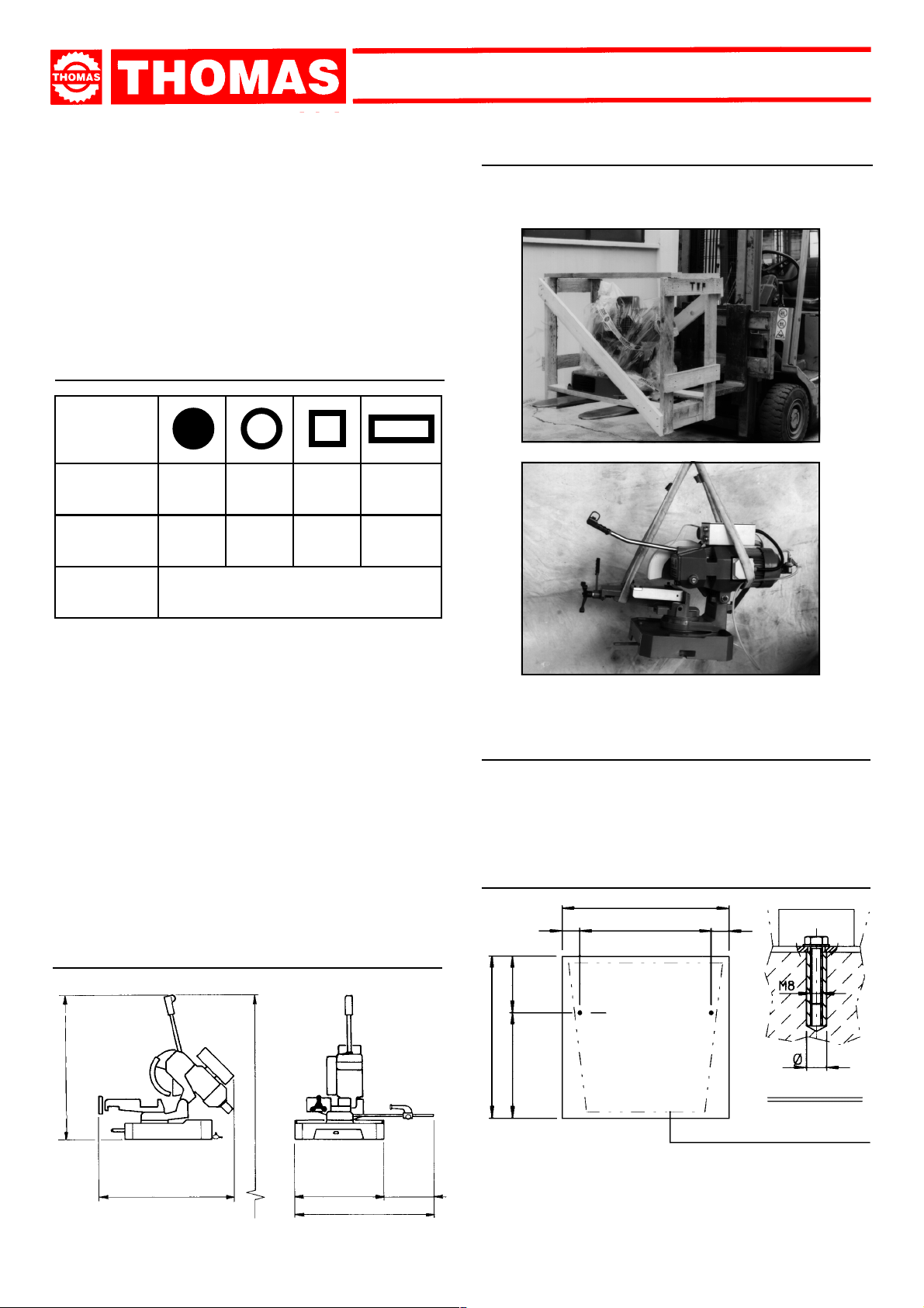
4.2 - Transport and handling of the machine
If the machine has to be shifted in its own packing, use a fork-lift
truck or sling it with straps as illustrated.
- Three-phase el. motor for 3-speed disk
rotation kW 1.35÷1.7÷2.4
- Single-phase el. motor for 1-speed disk
rotation kW 2.2
- Reduction gear in an oil bath Ratio = 1 : 32
- Maximum disk diameter mm 350
- Disk rotation speed rpm 22÷44÷88
- Vice opening mm 170
- Machine weight kg 1 86
MACHINE DIMENSIONS
TRANSPORT
4
INST ALLATION
DISMANTLING
4.1 - Machine dimensions
1150
4.3 - Minimum requirements for the premises
housing the machine
- Mains voltage and frequency complying with the machine motor
characteristics.
- Environment temperature from -10 °C to +50 °C.
- Relative humidity not over 90%.
4.4 - Anchoring the machine
690
7055070
185
AA
630
445
M8
12
SEC. A - A
1380
PEDEST AL PROFILE
1910 WITH PEDESTAL
530
420
950
- Position the machine on a firm cement floor, maintaining, at
the rear, a minimum distance of 800 mm from the w all; anchor
it to the ground as shown in the diagram, using screws and
expansion plugs or tie rods sunk in cement, ensuring that it is
sitting level.
5
Page 6
350 SUPER TECHNICS350 SUPER TECHNICS
350 SUPER TECHNICS
350 SUPER TECHNICS350 SUPER TECHNICS
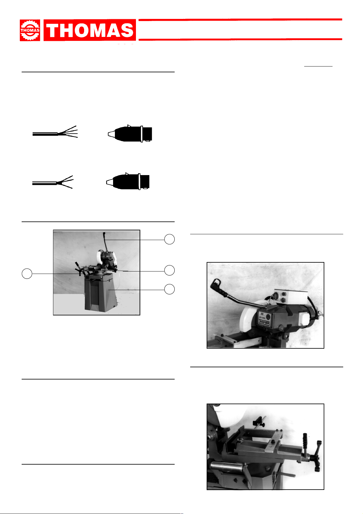
4.5 - Instructions for electrical connection
- The machine is not provided with an electric plug, so the
customer must fit a suitable one for his o wn working conditions:
1 - WIRING DIAGRAM FOR 5-WIRE SYSTEM FOR THREE-
PHASE MACHINE - SOCKET FOR A 16A PLUG
R = L1
S = L2
T = L3
PE = GND
2 - WIRING DIAGRAM FOR THE SINGLE-PHASE SYSTEM
SOCKET FOR A 16A PLUG
= L1
= L2
= PE
4.6 - Instructions for assembly of the loose parts
and accessories
1
1) Cast iron or ferrous materials, composed of metal alone, are
secondary raw materials, so they may be taken to an iron
foundry for re-smelting after having removed the contents
(classified in point 3);
2) electrical components, including the cable and electronic material (magnetic cards, etc.), fall within the category of material
classified as being assimilable to urban waste according
to the laws of the European community, so they may be set
aside for collection by the public waste disposal ser vice;
3) old mineral and synthetic and/or mixed oils, emulsified oils
and greases are special refuse, so they must be collected,
transported and subsequently disposed of by the old oil
disposal service.
NOTE: since standards and legislation concer ning refuse in
general is in a state of continuous evolution and theref ore
subject to changes and variations, the user must keep
informed of the regulations in force at the time of
disposing of the machine tool, as these may differ from
those described above, which are to be considered as
a general guide line.
MACHINE FUNCTIONAL
5
PARTS
5.1 - Operating head
- Machine par t composed of the par ts that transmit movement
(motor, reduction unit), the lubricating coolant pump and the
electrical components.
4
2
3
Fit the components supplied as indicated in the photo:
- par t. 1 Screw the lever onto the head and fix it
- par t. 2 Fit the bar holding rod
- par t. 3 Fix the pedestal firmly onto the base
- part. 4 Fit and align the roller carrying arm on the counter-
4.7 - Disactivating the machine
- If the sawing machine is to be out of use for a long period, it is
advisable to proceed as follows:
1) detach the plug from the electric supply panel
2) release the arch return spr ing
3) empty the coolant tank
4) carefully clean and grease the machine
5) if necessary, cover the machine.
vice bench.
5.2 - Vice
- System for gripping material dur ing the cutting operation, by
means of the approach handwheel and rapid manual or
pneumatic locking lever (optional).
It is provided with an anti-burr device for blocking the part that
is to be cut.
4.8 - Dismantling
(because of deterioration and/or obsolescence)
General rules
If the machine is to be permanently demolished and/or scrapped,
divide the material to be disposed of according to type and
composition, as follows:
6
Page 7
350 SUPER TECHNICS350 SUPER TECHNICS
350 SUPER TECHNICS
350 SUPER TECHNICS350 SUPER TECHNICS
5.3 - Bed
- Suppor t structure for the OPERATING HEAD (rotating ar m
for gradual cutting, with respectiv e blocking system), the VICE,
the BAR STOP, the material support R OLLER and the housing
for the cutting coolant TANK.
DESCRIPTION OF THE
6
OPERATING CYCLE
Before operating, all the main organs of the machine must
be set in optimum conditions (see the chapter on “Regulating
the machine”).
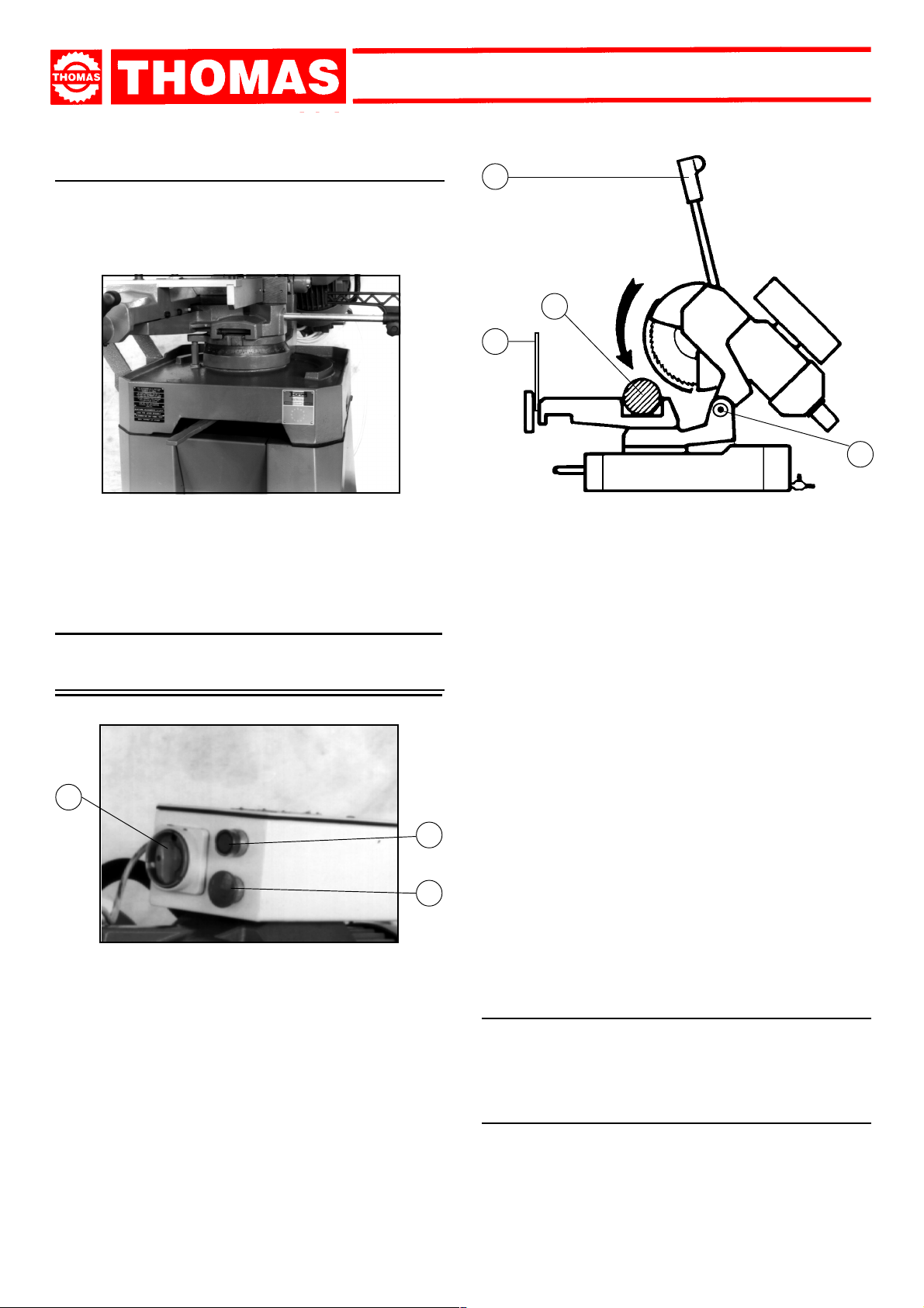
6.1 - Starting up and cutting cycle
6
4
5
7
and that sufficient coolant is coming out.
The cropper is now ready to start work, bearing in mind that the
CUTTING SPEED and the TYPE of DISC - combined with a
suitable descent of the head - are of decisive importance for
cutting quality and for machine performance (for further details
on this topic, see below in the chapter on “Material
classification and choice of disks”).
- When starting to cut with a new disk, in or der to safeguard
its life and efficiency, the first two or three cuts must be
made while exerting a slight pressure on the part, so that
the time taken to cut is about double the normal time (see
below in the chapter on “Material classification and choice
of disks” in the section on
Running in the disk
).
3
2
1
- Ensure that the machine is not in emergency stop condition;
if it is, release the red mushroom button ( 1 ).
- Select the cutting speed on the switch ( 3 ):
position 1 = 22 rpm.
position 2 = 44 rpm.
position 3 = 88 rpm.
- Press the star t/reset button ( 2 ): its green light will go on.
- Place material to be cut in the vice ( 4 ). Close jaws against
piece,keeping a distance of approx. 3 - 4 mm then clamp with
lever ( 5 ).
- Gr ip the handle ( 6 ) of the HEAD control arm and press the
button, checking that the disk is turning in the direction
indicated (if not, invert the two phase leads):
- Press the red emergency button ( 1 ) when there are conditions
of danger or malfunctions in general, so as to stop machine
operation immediately.
REGULATING
THE
7
MACHINE
7.1 - Disk head
- If excessive axial play is found on the hinge , it will be sufficient
to tighten the ring nuts ( 7 ), paying attention not to make the
joint too tight.
7.2 - Vice
- The device does not require any particular adjustment; in the
event of e xcessive play in the sliding guide, tighten the dowels
for adjusting the gib inside the slide.
7
Page 8
7.3 - Regulating arm blockage
- If there is insufficient blockage of the head arm in the desired
position, slacken the screw ( 1 ) on the lever, hold the bush
( 2 ) in position, turn the lever to the left and tighten the screw.
350 SUPER TECHNICS350 SUPER TECHNICS
350 SUPER TECHNICS
350 SUPER TECHNICS350 SUPER TECHNICS
1
2
1
BEFORE PERFORMING THE FOLLOWING OPERATIONS,
THE ELECTRIC POWER SUPPLY AND THE POWER CABLE
MUST BE COMPLETELY DISCONNECTED.
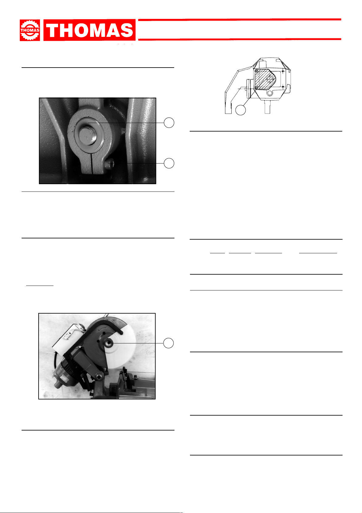
7.4 - Changing the disk
To change the disk:
- Release the mobile yellow, white or orange guard and turn it
back.
- Block a piece of wood in the vice and lean the disk on it.
- Inser t the special spanner provided and remove the screw
( 1 ), slackening it in a clockwise direction because it has a
left-handed thread, then slip off the flange that holds the disk.
- Fit the new disk, checking the cutting direction of the teeth,
then replace the flange, the screw and the mobile white, y ellow
or orange guard.
7.6 - Changing the lubricating coolant pump
- Take the pipes of the lubr icating-refrigerating system off.
- Remove the fastening screws and replace the little pump, being
careful to keep the driving system centred on the drive shaft bearing.
ANY REPLACEMENTS OF OTHER PARTS - SUCH AS THE
COMPONENTS OF THE REDUCTION GEAR, MOTOR AND
VARIOUS ELECTRIC PARTS - MUST BE CARRIED OUT BY
SKILLED OR COMPETENT PERSONNEL.
ROUTINE
AND SPECIAL
8
MAINTENANCE
THE MAINTENANCE JOBS ARE LISTED BELOW , DIVIDED
INTO
DAILY, WEEKLY, MONTHLY AND SIX-MONTHLY
INTERVALS. IF THE FOLLOWING OPERATIONS ARE
NEGLECTED, THE RESULT WILL BE PREMATURE WEAR
OF THE MACHINE AND POOR PERFORMANCE.
8.1 - Daily maintenance
- General cleaning of the machine to remove accumulated
shavings.
- Top up the level of lubricating coolant.
- Check the disk for wear.
- Lift the head into a high position to avoid yield stress on the
return spring.
- Check functionality of the shields and emergency stops.
1
7.5 - Clutch adjustment
Inside the head there is a clutch device which has already been
adjusted during assembly. If, after long use, further adjustment
is necessary, proceed as follows:
- remove the cover
- fit the template provided
- turn the motor shaft so that the ring nut ( 1 ) is in a convenient
position to allow it to be tightened or slackened enough to
calibrate the clutch system.
8
8.2 - Weekly maintenance
- More accurate general cleaning of the machine to remove
shavings, especially from the lubricant fluid tank.
- Clean the filter of the pump suction head and the suction
area.
- Clean and grease the screw and the sliding guide of the vice.
- Clean the disk housing.
- Shar pen the disk teeth.
8.3 - Monthly maintenance
- Check tightness of the screws on the motor, the pump, the
jaws and shields.
- Check that the shields are unbroken.
- Grease the head hinge pin.
8.4 - Six-monthly maintenance
- Change the oil in the reduction unit using oil type GEARCO
85W-140 by NATIONAL CHEMSERACH or MOBIL GLYCOLE
30 or KLUBER SINTHESO 460 EP or an equivalent oil,
proceeding as follows:
Page 9

350 SUPER TECHNICS350 SUPER TECHNICS
350 SUPER TECHNICS
350 SUPER TECHNICS350 SUPER TECHNICS
1
- Remove the connecting plug
from the electric box and unscrew the head moving lev er.
- Drain off the old oil from the
cap ( 1 ).
- Pour in new oil up to the
mark ( 1 ), through the lever
fixing hole, keeping the head
in upper position ( 2 ).
- Reassemble all the par ts.
- Check continuity of the equipotential protection circuit
2
8.5 - Oils for lubricating coolant
Considering the vast range of products on the market, the user
can choose the one most suited to his own requirements, using
as reference the type SHELL LUTEM OIL ECO.
THE MINIMUM PERCENTAGE OF OIL DILUTED IN WATER
IS 8 - 10 %.
8.6 - Oil disposal
The disposal of these products is controlled by strict regulations.
Please see the Chapter on “Machine dimensions - Transport
- Installation” in the section on
Dismantling
.
8.7 - Special maintenance
Special maintenance operations must be carried out by skilled
personnel. Ho wever , we advise contacting THOMAS or their dealer
and/or importer. The term special maintenance also covers the
resetting of protection and safety equipment and devices.
MATERIAL
CLASSIFICATION AND
9
CHOICE OF TOOL
Since the aim is to obtain excellent cutting quality , the various
parameters such as hardness of the material, shape and
thickness, transverse cutting section of the part to be
cut, choice of the type of cutting disk, cutting speed and
control of head descent, must be suitably combined.These
specifications must therefore be harmoniously combined in
a single operating condition according to practical
considerations and common sense, so as to achieve an
optimum condition that does not require countless operations
to prepare the machine when there are many variations in
the job to be performed.The various problems that crop up
from time to time will be solved more easily if the operator
has a good knoledge of these specifications.
WE THEREFORE ADVISE YOU ALWAYS TO CHOOSE
ORIGINAL SPARE DISKS THAT GUARANTEE SUPERIOR
QUALITY AND PERFORMANCE.
9.1 - Definition of materials
The table at the foot of the page lists the characteristics of the
materials to be cut, so as to choose the right tool to use.
USE
Construction
steels
Carbon
steels
Spring steels
Alloyed steels for
hardening and
tempering and for
nitriding
Alloyed
casehardening
steels
Steel for
bearings
Tool steel
Stainless
steel
Copper alloys
Special brass
Bronze
Cast iron
TYPES OF STEEL CHARACTERISTICS
I
UNI
Fe360
Fe430
Fe510
C20
C40
C50
C60
50CrV4
60SiCr8
35CrMo4
39NiCrMo4
41CrAlMo7
18NiCrMo7
20NiCrMo2
100Cr6 100Cr6 100C6 534 A 99 52100 207 95 690÷980
52NiCrMoKU
C100KU
X210Cr13KU
58SiMo8KU
X12Cr13
X5CrNi1810
X8CrNi1910
X8CrNiMo1713
Aluminium copper alloy G-CuAl11Fe4Ni4 UNI 5275
Special manganese/silicon brass G-CuZn36Si1Pb1 UNI5038
Manganese bronze SAE43 - SAE430
Phosphor bronze G-CuSn12 UNI 7013/2a
Gray pig iron G25
Spheroidal graphite cast iron GS600
Malleable cast iron W40-05
D
DIN
St37
St44
St52
CK20
CK40
CK50
CK60
50CrV4
60SiCr7
34CrMo4
36CrNiMo4
41CrAlMo7
----
21NiCrMo2
56NiCrMoV7
C100W1
X210Cr12
----
4001
4301
----
4401
F
AF NOR
E24
E28
E36
XC20
XC42H1
----
XC55
50CV4
----
35CD4
39NCD4
40CADG12
20NCD7
20NCD2
----
----
Z200C12
Y60SC7
----
Z5CN18.09
----
Z6CDN17.12
GB
SB
---43
50
060 A 20
060 A 40
----
060 A 62
735 A 50
----
708 A 37
----
905 M 39
En 325
805 H 20
----
BS 1
BD2 - BD3
----
----
304 C 12
----
316 S 16
USA
AISI-SAE
----
----
---1020
1040
1050
1060
6150
9262
4135
9840
---4320
4315
----
S-1
D6 - D3
S5
410
304
----
316
Hardness
BRINELL
HB
116
148
180
198
198
202
202
207
224
220
228
232
232
224
244
212
252
244
202
202
202
202
220
140
120
100
212
232
222
Hardness
ROCKWELL
HRB
67
80
88
93
93
94
94
95
98
98
99
100
100
98
102
96
103
102
94
94
94
94
98
77
69
56,5
96
100
98
R=N/mm2
360÷480
430÷560
510÷660
540÷690
700÷840
760÷900
830÷980
1140÷1330
1220÷1400
780÷930
880÷1080
930÷1130
760÷1030
690÷980
800÷1030
710÷980
820÷1060
800÷1030
670÷885
590÷685
540÷685
490÷685
620÷685
375÷440
320÷410
265÷314
245
600
420
9
Page 10

350 SUPER TECHNICS350 SUPER TECHNICS
350 SUPER TECHNICS
350 SUPER TECHNICS350 SUPER TECHNICS
9.2 - Choosing the disk
First of all the pitch of the teeth must be chosen, suitable for
thematerial to be cut, according to these criteria:
- parts with a thin and/or variable section such as profiles , pipes
and plate, need close toothing, so that the number of teeth
used simultaneously in cutting is from 3 to 6;
- par ts with large transverse sections and solid sections need
widely spaced toothing to allow for the greater volume of the
shavings and better tooth penetration;
- parts made of soft material or plastic (light alloys, mild bronze,
teflon, wood, etc.) also require widely spaced toothing.
9.3 - Teeth pitch
As already stated, this depends on the following factors:
- hardness of the material
- dimensions of the section
- thickness of the wall.
S (MM) PICTH SHAPE SPEED
B
shaped
C
solid
C
solid
C
solid
C
solid
C
solid
C
solid
3
3 - 2
2
2
2
1
1
S
SS
up to 2 4 - 6
2 ÷ 5 8
5 ÷ 10 8
over 10 8
up to 20 8
20 ÷ 50 10
50 ÷ 65 13 ÷
9.4 - Cutting and advance speed
The cutting speed (m/min) and the advance speed (cm2/min =
area travelled by the disk teeth when removing shavings) are
limited by the development of heat close to the tips of the teeth.
- The cutting speed is subordinate to the resistance of the
material (R = N/mm
dimensions of the widest section.
- Too high an advance speed (= disk descent) tends to cause
the disk to deviate from the ideal cutting path, producing non
rectilinear cuts on both the vertical and the horizontal plane.
2
), to its hardness (HRC) and to the
9.5 - Running in the disk
9.7 - Type of disks
The disks differ essentially in their constructive characteristics,
such as:
- Tooth shape
- Tooth cutting angle
Tooth shape
The profile of the toothing depends on the size, shape and
thickness of the section to be cut, either straight or at an angle.
It may also vary according to the pitch, but not so distinctly as to
make this an element for classification.
- Fine toothing is to be chosen for cutting small sections with a
profiled shape and tubular sections with thin walls (2-5 mm
depending on the material).
- Large toothing is suitable for cutting medium and large solid
sections or fairly thick profiled or tubular sections (o ver 5 mm).
"A" toothing:
normal fine toothing
"B" toothing:
normal large toothing with or
without shaving breaking incision
“C (HZ)” toothing:
large toothing with roughing
tooth with rake on both sides,
alternating with a finishing
tooth without rake. The roughing tooth is 0.15-0.30 mm
higher
Tooth cutting angle
Each tooth has two cutting angles:
αα
α : front rake angle
-
αα
γγ
-
γ : rear rake angle
γγ
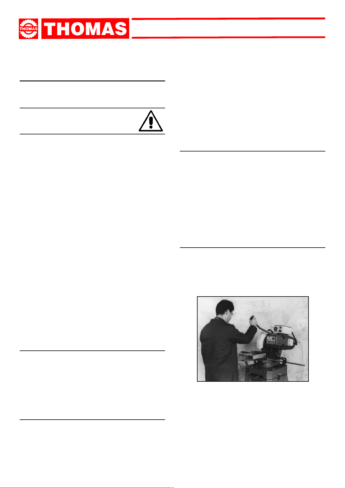
SHARPENING CIRCULAR SAWS
"AW" toothing:
fine toothing with alternate
side rake
"BW" toothing:
large toothing with alternate
side rake
Added toothing:
disks made in this way are
used for cutting non-ferrous
metals, such as light alloys,
and plastics, and above all in
wood-working. The teeth are
hard metal (HM) plates brazed
onto the body of the disk; there
are various types and shapes
and, considering the vastness
of the field, the topic is not
developed further here.
When cutting for the first time, it is good practice to run in
the tool making a series of cuts at a low advance speed
(= 30-35 cm
to the cutting capacity and solid section of normal steel with
R = 410-510 N/mm
with lubricating coolant.
2
/min on material of average dimensions with respect
2
), generously spraying the cutting area
9.6 - Disk structure
The most commonly used disks are made of extra high speed
steel (HHS) of normal quality (HHS/DMo5) or superior quality
(HHS/Mo5 + Co5) with a treated tooth, which differentiates them
from the former on account of the high value of structural
resistance, greater resistance to seizing, absence of stress in
the mass and a better holding of lubricating coolant during work.
10
αα
α
αα
γγ
γ
γγ
T
3 4 5 6 7 8 9 10 12 14 16
1,3 1,6 2,1 2,5 2,9 3,4 3,8 4,2 5,1 5,9 7,2
p
1,5 2 2,5 3 3,5 4 4,5 5 6 7 8
d
h = 0,2 mm h = 0,3 mm
The rake varies especially according to the type of material
to be cut.
Page 11

9.7.1 - RECOMMENDED CUTTING PARAMETERS
2
2
Mild steel
R = 350-500 N/mm
Semi-hard steel
R = 500-700 N/mm
CUTTING ANGLES
*T mm
Vt m/1'
Av mm/1'
*T mm
Vt m/1'
Av mm/1'
*T mm
Vt m/1'
Av mm/1'
*T mm
Vt m/1'
Av mm/1'
*T mm
Vt m/1'
Av mm/1'
SECTION TO BE CUT (IN MM)
RECOMMENDED LUBRIFICANTS Emulsion - Cutting oil
*T mm
Vt m/1'
Av mm/1'
*T mm
Vt m/1'
Av mm/1'
2
2
Extra-hard steel
Hard steel
R = 950-1000 N/mm
R = 750-950 N/mm
Heat-treated steel
2
2
Austentic stainless
steel
R = 500-800 N/mm
Martensitic stainless
R = 950-1300 N/mm
steel
2
R = 500-800 N/mm
Grey cast iron
Aluminium and alloys
R = 200-400 N/mm2Copper
Kerosene
Dry
2
Aluminium and alloys
Dry
350 SUPER TECHNICS350 SUPER TECHNICS
350 SUPER TECHNICS
350 SUPER TECHNICS350 SUPER TECHNICS
2
2
2
R = 300-300 N/mm
R = 200-350 N/mm
Phosphor bronze
R = 400-600 N/mm
Emulsion
2
Hard bronze
R = 600-900 N/mm
2
Brass
R = 200-400 N/mm2Titanium and alloys
Alloyed brass
Cutting oil Emulsion
R = 300-800 N/mm
R = 400-700 N/mm
2
2
Tubes and beams
Tubes and beams
0,025. D
0,05. D
R = 300-600 N/mm
R = 300-600 N/mm
9.7.2 - DIAGRAM OF CUTTING SPEEDS ACCORDING TO DISK DIAMETER
Vt m/min
KEY
T Tooth pitch in millimetres
Av mm/min Advance in millimetres per minute
Vt m/min Cutting speed in metres per minute
Az Tooth advance
Ng/min Number of revs per minute
Z Number of teeth on the disk
p Tooth depth
d Diameter of the tooth fillet cone distance
h Tooth protrusion
γ Front rake
α Rear rake
N/mm Ultimate tensile stress
a-f Flat parts of the cutting edge
Ø Tube diameter or profile width
n = g/min
11
Page 12

350 SUPER TECHNICS350 SUPER TECHNICS
350 SUPER TECHNICS
350 SUPER TECHNICS350 SUPER TECHNICS
10
MACHINE COMPONENTS
10.1 - List of spare parts
REFERENCE N° DESCRIPTION
1 Machine bed
2 Revolving arm
3 Revolving arm locking pin
4 Revolving arm locking bush
5 Revolving arm locking leve r
6 Screw M10
7 Countervice
8 Mobile countervice
9 Countervice jaws
10 Burr-free jaws
11 Countervice rotation
locking pin
12 Roller arm
13 Roller
14 Nut M12
15 Screw M12
16
17 Vice
18 Vice jaws
19 Vice jaw washer
20 Screw M12
21 Washer
22 Screw M12
23 Grain M8
24 Lever bush
25 Quick lock vice lever
26 Thrust bearing AX 3047
+ counter-bearing CP 3047
27 Quick lock vice lever washer
28 Vice handwheel
29 Pin Ø 6
30 Washer
31 Screw M8
32 Vice gib
33 Grain M8
34 Nut M8
35 Vice thread
36 Quick lock vice spring
37 Burr-free transverse plate
REFERENCE N° DESCRIPTION
38 Burr-free plate
39
40 Screw M8
41 Crucible
42 Screw M6
43 Bar stop rod
44 Ruler
45 Screw M2
46 Bar stop
47 Oiler Ø 8
48 Grain M8
49 Tank cover gasket
50 Ring seeger Ø 42I
51 Tank cover filter
52 Tank cover wire gauze
53 Tank cover
54 Washer
55 1/4 gas tap
56 Coolant tube
57 Extra shield
58 Spring connection
59 Head return spring
60 Nut M12
61 Screw M12
62 Head
63 3/8 gas tap
64 GUK M25x1,5 ring nut
65 Spring thrusting washer
66 Oil level and drain plug 1/2 gas
67 Hinge cylindrical pin
68 GUK M25x1,5 ring nut
69 Hinge eccentric pin
70 Eccentric bush
71 Bearing 6202
72 Nut M20
73 Head lever
74 Head lever handgrip
75 Bush
76 Bearing 32008X
12
Page 13

350 SUPER TECHNICS350 SUPER TECHNICS
350 SUPER TECHNICS
350 SUPER TECHNICS350 SUPER TECHNICS
REFERENCE N° DESCRIPTION
N° RIFERIMENTO DENOMINAZIONE
REFERENCE N° DESCRIPTION
N° RIFERIMENTO DENOMINAZIONE
77 Ring DPSM 50728
78 Cylindric pin Ø 5x12
79 Disk shaft
80 Disk
81 Disk shaft flange
82 TCCE M12x35 l.h. Screw
83 Fixed blade guard
84 Grain M8
85 Front head cover
86 Cooling distributor
87 Coolant tube
88 Grain M6
89 Mobile blade guard
90 Ring seeger Ø 60E
91 Pin
92
93 Tie rod support
94 Screw M6
95 Screw M6
96 Tie rod
97 Ring seeger Ø 10E
98 Tie rod support pin
99 Ring OR 4205
100 GUK M20x1 ring nut
101 Worm screw
102 Worm screw spacer
103 Ring seeger Ø 62I
104 Bearing 3305
105 Ring SM 32527
106 OR-Rings 4312
107 Front motor flange
108 Motor shaft (rotor)
109 Key 5x6x35
110 Washer
111 Stud bolt
112 Nut
113 Motor housing and stator
114 Switch box
115 Ring OR 3081
116 Motor rear cover
117 Ring seeger Ø 25E
118 Head cover gasket
REFERENCE N° DESCRIPTION
REFERENCE N° DESCRIPTION
119 Nilos Ring 4205 AV
120 Bearing 4205
121 Motor fan
122 Fan cover
123 Bearing 609
124 Ring seeger Ø 9E
125 Pump connection box
126 Gasket
127 Screw M4
128 Coolant pump
129 Washer
130 Screw M6
131 Clutch cone
132 Worm wheel
133 Clearance adjustment ring
134 KM8 M40x1,5 ring nut
135 Safety washer MB8
136 Cup springs 50x25 - 4x3
137 Disk shaft flange pin
13
Page 14

350 SUPER TECHNICS350 SUPER TECHNICS
350 SUPER TECHNICS
350 SUPER TECHNICS350 SUPER TECHNICS
14
Page 15

KEY
140 Auxiliary relay
141 Remote-control switch
142 Fuse carrier
143 Transformer
144 Socket connector
145 Plug connector
143
140
141
350 SUPER TECHNICS350 SUPER TECHNICS
350 SUPER TECHNICS
350 SUPER TECHNICS350 SUPER TECHNICS
142
144
145
147
146
KEY
146 Speed switch
147 Reset button
148 Emergency button
149 Electric components box
150 Box cover
151 Box gasket
148
149
151150
15
Page 16

350 SUPER TECHNICS350 SUPER TECHNICS
350 SUPER TECHNICS
350 SUPER TECHNICS350 SUPER TECHNICS
11
WIRING DIAGRAMS
SINGLE-PHASE
CIRCUIT DIAGRAM THREE-POLE
350 SUPER TECHNICS
16
V 230 / 50 Hz
CODE DESCRIPTION
SQ1 Microswitch
SB1 Mushroom button
SB2 Luminous button
HL Pilot lamp
KA Auxiliary relay
KM Remote-control switch
ST1 Thermal probe
350 SUPER TECHNICS THREE-POLE SINGLE-PHASE
CODE DESCRIPTION
M1 Disk motor
XP Socket
XS Plug
QS Isolating switch
C Condenser
FU1 Fuse cartridge
FU2 Fuse cartridge
TC1 Transformer
Page 17

350 SUPER TECHNICS350 SUPER TECHNICS
350 SUPER TECHNICS
350 SUPER TECHNICS350 SUPER TECHNICS
350 SUPER TECHNICS
CIRCUIT DIAGRAM THREE-PHASES
V 400 / 50 Hz
CODE DESCRIPTION
SQ1 Microswitch
SB1 Mushroom button
SB2 Luminous button
HL Pilot lamp
KA Auxiliary relay
KM Remote-control switch
ST1 Thermal probe
350 SUPER TECHNICS THREE-PHASES
CODE DESCRIPTION
M1 Disk motor
XP Socket
XS Plug
SA Switch
FU1 Fuse cartridge
FU2 Fuse cartridge
TC1 Transformer
17
Page 18

350 SUPER TECHNICS350 SUPER TECHNICS
350 SUPER TECHNICS
350 SUPER TECHNICS350 SUPER TECHNICS
12
This chapter lists the probable faults and malfunctions that could occur while the machine is being used and suggests possible
remedies for solving them.
The first paragraph provides diagnosis for TOOLS and CUTS, the second for ELECTRICAL COMPONENTS.
TROUBLESHOOTING
12.1 - Blade and cut diagnosis
FAULT PROBABLE CAUSE REMEDY
TOOTH BREAKAGE Too fast advance
Wrong cutting speed
Wrong tooth pitch
Low quality disk
Ineffective gripping of the part in the
vice.
Previously broken tooth left in the cut
Cutting resumed on a groove made
previously.
Insufficient lubricating refrigerant or
wrong emulsion
Sticky accumulation of material on
the disk.
Decrease advance, exer ting less cutting
pressure
Change disk speed and/or diameter.
“
See Chapter
and choice of disks”
cutting speeds according to disk diameter.
Choose a suitable disk.
See Chapter “Material classification
and choice of disks”.
Use a better quality disk.
Check the gripping of the part.
Accurately remove all the parts left in.
Make the cut elsewhere, turning the part.
Check the level of the liquid in the tank.
Increase the flow of lubricating refrigerant,
checking that the hole and the liquid outlet
pipe are not blocked.
Check the blend of lubricating coolant and
choose a better quality disk.
Material classification
and the
Table of
PREMATURE DISK WEAR Wrong running in of the disk
Wrong cutting speed
Unsuitable tooth profile
Wrong tooth pitch
Low quality disk
Insufficient lubricating refrigerant
CHIPPED DISK
Hardness, shape or flaws in the material (oxides, inclusions, lack of homogeneity, etc..)
Wrong cutting speed
Wrong tooth pitch
Vibrations
Disk incorrectly sharpened
Low quality disk
See Chapter “Material classification
and choice of disks”
Running in the disk.
on
Change disk speed and/or diameter.
See Chapter “Material classification
and choice of disks” and the
cutting speeds according to disk diameter.
Choose a suitable disk. See Chapter
“Material classification and choice of
disks” in the paragraph on
Choose a suitable disk.
See Chapter “Material classification
and choice of disks”.
Use a better quality disk.
Check the level of the liquid in the tank.
Increase the flow of lubricating refrigerant,
checking that the hole and the liquid outlet
pipe are not blocked.
Reduce the cutting pressure and/or the
advance.
Change disk speed and/or diameter. See
Chapter “Material classification and
choice of disks” and the
speeds according to disk diameter.
Choose a suitable disk.
See Chapter “Material classification
and choice of disks”.
Check gripping of the part.
Replace the disk with one that is more
suitable and correctly sharpened.
Use a better quality disk.
in the paragraph
Table of
Type of disks.
Tab le of cutting
18
Page 19

350 SUPER TECHNICS350 SUPER TECHNICS
350 SUPER TECHNICS
350 SUPER TECHNICS350 SUPER TECHNICS
FAULT PROBABLE CAUSE REMEDY
DISK VIBRATION
RIDGES ON THE CUTTING SURFACE
Incorrect emulsion of the lubricating
refrigerant
Wrong tooth pitch
Unsuitable tooth profile
Ineffective gripping of the part in the
vice.
Dimensions of the solid section too
large with respect to the maximum
admissible cutting dimensions
Disk diameter incorrect and/or too
large
Disk diameter incorrect and/or too
large
Ineffective gripping of the part in the
vice.
Too fast advance
Disk teeth are worn
Insufficient lubricating refrigerant
Toothing does not unload shavings
well
Check the percentage of water and oil in
the emulsion.
Choose a suitable disk.
See Chapter “Material classification
and choice of disks” .
Choose a suitable disk.
See Chapter
and choice of disks”
on Type of disks.
Check the gripping of the part.
Abide by the instructions.
Decrease the disk diameter, adapting it
to the dimensions of the part to be cut;
the cutting part of the disk must not be
too large for the shape of the part to be
cut.
Decrease the disk diameter, adapting it
to the dimensions of the part to be cut;
the cutting part of the disk must not be
too large for the shape of the part to be
cut. Check the gripping of the par t.
Decrease advance, exe rting less cutting
pressure.
Sharpen the tool.
Check the level of the liquid in the tank.
Increase the flow of lubricating refrigerant,
checking that the hole and the liquid outlet
pipe are not blocked.
Choose a blade with a larger tooth pitch
that allows better unloading of shavings
and that holds more lubricating
refrigerant.
“Material classification
in the paragraph
CUTS OFF THE STRAIGHT
BLADE STICKS IN THE CUT
Too fast advance
Ineffective gripping of the part in the
vice
Disk head off the straight
Disk sides differently sharpened.
Disk thinner than the commercial
standard.
Dirt on the gripping device
Too fast advance
Low cutting speed
Wrong tooth pitch
Sticky accumulation of material on
the disk.
Insufficient lubricating refrigerant
Centering the piece with the disk
Decrease advance, exe rting less cutting
pressure.
Check the gripping of the part which may
be moving sideways.
Adjust the head.
Choose tool quality carefully in every detail
as regards type and construction characteristics.
Carefully clean the laying and contact
surfaces.
Decrease advance, exe rting less cutting
pressure.
Increase speed.
Choose a suitable disk.
See Chapter “Material classification
and choice of disks” .
Check the blend of lubricating coolant and
choose a better quality disk.
Check the level of the liquid in the tank.
Increase the flow of lubricating refrigerant,
checking that the hole and the liquid outlet
pipe are not blocked.
Always adjust the counter-vice in a position
where it block the piece as perpendicular
as possible to the cutting line.
19
Page 20

350 SUPER TECHNICS350 SUPER TECHNICS
350 SUPER TECHNICS
350 SUPER TECHNICS350 SUPER TECHNICS
12.2 - Electrical components diagnosis
FAULT PROBABLE CAUSE REMEDY
THE GREEN PILOT LIGHT
“HL” DOES NOT LIGHT UP
Fused lamp
Power supply
Fuses “FU 1”
Short circuits
Speed switch “SA” in position “0”
Emergency button “SB 1” on
Cycle reset or line button “SB 2”
Thermal probe built into the stator
winding has tripped due to motor
overheating
Transformer “TC 1”
Fuse “FU 2”
Auxiliary relay “KA”
Change it.
Check: - phases
- cables
- socket
- plug
Voltage must arrive upstream from the
fuses.
Check for efficiency.
Identify and eliminate.
It must be turned to position 1 or 2.
Ensure that it is off and that its contacts
are unbroken.
Check mechanical efficiency.
Check current continuity on the two wires
in the prone after letting the motor cool
for about 10-15 minutes. If after this time
there is no current continuity in the two
wires, the motor must be changed or
rewound. Check that the supply
voltage is the same as the line voltage
and that it gives a value of 24 V at output.
Check fuse efficiency and ensure there
are no short circuits causing the protection
to trip.
Check that 24 V reach the coil terminals
when the button “SB 2” is pressed; if this
happens and the relay is not self-fed, it
must be changed.
MOTOR STOPPED WITH PILOT
LIGHT “HL” LIT
13
In accordance with point 1.7.4.f of the Machines Directive EEC 89/392
PRECISION PHONOMETER MOD. CEL-LUCAS 275-2B
INTEGRATING METER CLASS 1 IEC 651 - IEC 804 REGULATIONS
PRECISION GAUGE CEL-LUCAS 284/2 IEC 942 REGULATIONS
4 measurements with the machine operating unloaded.
- The microphone was been located close to the operator's head, at medium height.
- The weighted equivalent continuous acoustic pressure level was 81,5 dB (A).
- The maximum level of the WEIGHTED instantaneous acoustic pressure C was always less than 130 dB.
NOTE: with the machine operating, the noise level will vary according to the different materials being processed. The user must
there-fore assess the intensity and if necessary provide the operators with the necessary personal protection, as required by Law
277/1991.
NOISE TESTS
Socket and plug connecting the
electric box/ microswitch in the handle
Microswitch “SQ 1” in the handle
Remote-control switch “KM”
Motor “M 1”
Check that the plug is correctly inserted
and look for any bad connections inside
the box.
Check operation and/or efficiency; replace
if broken.
Check that phases are present at both
input and output; ensure that it is not
blocked, that it closes when fed, that it
does not cause short circuits; otherwise
change it.
Check that it is not burnt and that it turns
freely.
It may be rewound or changed.
20
Page 21

350 SUPER TECHNICS350 SUPER TECHNICS
350 SUPER TECHNICS
350 SUPER TECHNICS350 SUPER TECHNICS
14
14.1 - Pneumatic vice
- System for clamping material during the cutting operations,
14.2 - Connection to the pneumatic system
OPTIONAL
with an automated pneumatic device.
It is provided with an anti-burr device for blocking the part of
the piece that has been cut off.
2
1
1
- Connect the tube of the pneumatic system to the filter unit
part ( 1 ) and check that the pressure gauge part ( 2 ) shows
a pressure of 6 - 7 BAR, sufficient to ensure optimum
functioning of the device.
PLATES AND LABELS
- The vice opening mechanism is controlled by the valve part
( 1 ) operated only if the head is completely lifted.
- Leave a play of 3 - 4 mm between the jaw and the piece to be
clamped, then lower the head to block the piece.
21
Page 22

350 SUPER TECHNICS350 SUPER TECHNICS
350 SUPER TECHNICS
350 SUPER TECHNICS350 SUPER TECHNICS
NOTES: _________________________________________________________________________
________________________________________________________________________________
________________________________________________________________________________
________________________________________________________________________________
________________________________________________________________________________
________________________________________________________________________________
________________________________________________________________________________
________________________________________________________________________________
________________________________________________________________________________
________________________________________________________________________________
________________________________________________________________________________
________________________________________________________________________________
________________________________________________________________________________
________________________________________________________________________________
________________________________________________________________________________
________________________________________________________________________________
________________________________________________________________________________
________________________________________________________________________________
________________________________________________________________________________
________________________________________________________________________________
________________________________________________________________________________
________________________________________________________________________________
________________________________________________________________________________
________________________________________________________________________________
________________________________________________________________________________
________________________________________________________________________________
________________________________________________________________________________
________________________________________________________________________________
________________________________________________________________________________
________________________________________________________________________________
________________________________________________________________________________
________________________________________________________________________________
________________________________________________________________________________
________________________________________________________________________________
________________________________________________________________________________
________________________________________________________________________________
________________________________________________________________________________
22
Page 23

350 SUPER TECHNICS350 SUPER TECHNICS
350 SUPER TECHNICS
350 SUPER TECHNICS350 SUPER TECHNICS
________________________________________________________________________________
________________________________________________________________________________
________________________________________________________________________________
________________________________________________________________________________
________________________________________________________________________________
________________________________________________________________________________
________________________________________________________________________________
________________________________________________________________________________
________________________________________________________________________________
________________________________________________________________________________
________________________________________________________________________________
________________________________________________________________________________
________________________________________________________________________________
________________________________________________________________________________
________________________________________________________________________________
________________________________________________________________________________
________________________________________________________________________________
________________________________________________________________________________
________________________________________________________________________________
________________________________________________________________________________
________________________________________________________________________________
________________________________________________________________________________
________________________________________________________________________________
________________________________________________________________________________
________________________________________________________________________________
________________________________________________________________________________
________________________________________________________________________________
________________________________________________________________________________
________________________________________________________________________________
________________________________________________________________________________
________________________________________________________________________________
________________________________________________________________________________
________________________________________________________________________________
________________________________________________________________________________
________________________________________________________________________________
________________________________________________________________________________
________________________________________________________________________________
23
Page 24

 Loading...