

Daitsu FSTD SLIM-01, FSTD SLIM-01-4T, FSTD SLIM-02, FSTD SLIM-02-4T, FSTD SLIM-03 Installation And Maintenance Manual
...Page 1

INSTALLATION AND MAINTENANCE MANUAL
FLOOR CEILING SLIM
FSTD SLIM - EC FLEX
Serie
FSTD SLIM - EC FLEX
Edition
R00
Models
FSTD SLIM-01
FSTD SLIM-02
FSTD SLIM-03
FSTD SLIM-04
FSTD SLIM-05
FSTD SLIM-01-4T
FSTD SLIM-02-4T
FSTD SLIM-03-4T
FSTD SLIM-04-4T
FSTD SLIM-05-4T
Page 2

INVESTING IN QUALITY, RELIABILITY & PERFORMANCE
ISO 9001 QUALITY
World Leading Design and Technology
Every product is manufactured to meet
the stringent requirements of the
internationally recognized ISO 9001
standard for quality assurance in design,
development and production.
Equipped with the latest air-conditioning test rooms
and manufacturing technology, we produce over
50,000 fan coil units each year, all conforming to the
highest international standards of quality and safety.
CE SAFETY STANDARDS
The Highest Standards of Manufacturing
All products conform to the Certificate
Europe directives (Machinery Safety,
Electromagnetic Compatibility and Low
Voltage), as required throughout the
European Community, to guarantee
correct standards of safety.
In order to guarantee the very highest standards and
performance, we manage every stage in the
manufacturing of our products. Throughout the
production process we maintain strict control,
starting with our extensive resources in research and
development through to the design and
manufacture of almost every individual component,
from molded plastics to the assembly of units and
controllers.
WEEE MARK
Quality Controlled from Start to Finish
All products conform to the “WEEE”
directive to guarantee correct standards
of environmental solutions.
Our highly trained staff and strict quality control
methods enable us to produce products with an
exceptional reputation for reliability and efficiency,
maintained over many years. As well as CE
certification and ISO 9001, several products ranges
have UL / ETL safety approval in the USA and Canada,
Eurovent performance and sound certification as
well as ROHS compliance for Europe, giving you the
confidence of knowing our company is the right
choice when selecting fan coil units.
Page 1 of 71
ALWAYS MAKE SURE THIS MANUAL REMAINS WITH THE UNIT. READ THIS MANUAL BEFORE PERFORMING ANY
OPERATION ON THE UNIT.
SK2019 FSTD-SLIM-EC-FLEX-001_01
Page 3

Page 2 of 71
Table of Contents
A. Technical Data ...................................................................................................................................................................... 5
General Description ........................................................................................................................................................ 5
General Specification ..................................................................................................................................................... 6
2-Pipe Systems ........................................................................................................................................................ 6
4-Pipe Systems ........................................................................................................................................................ 7
Coil Data ........................................................................................................................................................................ 8
2-Pipe Systems ........................................................................................................................................................ 8
4-Pipe Systems ........................................................................................................................................................ 8
Sound Power Data .......................................................................................................................................................... 9
Dimensions .................................................................................................................................................................. 14
Valve Information (Optional) ........................................................................................................................................ 15
B. Installation ......................................................................................................................................................................... 18
Safety Precautions ........................................................................................................................................................ 18
Installation and Location .............................................................................................................................................. 19
Front Panel Removal .................................................................................................................................................... 20
Electrical Connection .................................................................................................................................................... 20
Piping Connections ....................................................................................................................................................... 22
Valve and External Drain Pan Installation ..................................................................................................................... 23
C. Maintenance ...................................................................................................................................................................... 25
General Maintenance ................................................................................................................................................... 25
Regular Maintenance ................................................................................................................................................... 25
Filter Installation & Cleaning ........................................................................................................................................ 25
Fan Motor Assembly Maintenance ............................................................................................................................... 26
Water Fittings Interchange ........................................................................................................................................... 26
D. Control Specifications: Complete Function PCB – TOTAL Type Control .............................................................................. 27
I/O Port Definitions ...................................................................................................................................................... 27
Wiring Diagrams .......................................................................................................................................................... 28
Standard EC-TOTAL Type Control PCB .................................................................................................................... 28
Master-Slave Networking Wiring Diagram ............................................................................................................. 29
Configuration Settings .................................................................................................................................................. 30
Control Logics for 2-Pipe System ................................................................................................................................... 32
With Valve Configuration ....................................................................................................................................... 32
Without Valve Configuration ................................................................................................................................. 35
Control Logics For 4-Pipe System .................................................................................................................................. 37
Sleep Mode .................................................................................................................................................................. 39
Auto Fan Speed ............................................................................................................................................................ 39
Modulating Valve Control Under Energy Saving Mode ................................................................................................. 39
Buzzer .......................................................................................................................................................................... 39
Auto Restart ............................................................................................................................................................... 39
On/Off Switch On The Front Panel .............................................................................................................................. 40
Electric Heater Safety Switch ...................................................................................................................................... 40
SK2019 FSTD-SLIM-EC-FLEX-001_01
Page 4

Page 3 of 71
Low Temperature Protection of Indoor Coil in Winter ................................................................................................. 40
E. Networking System ............................................................................................................................................................ 41
Master-Slave Network .................................................................................................................................................. 41
Master Unit Control Settings .................................................................................................................................. 41
Master-Slave Network Setup ................................................................................................................................. 42
Master-Slave Communication Method ................................................................................................................... 44
Open Modbus protocol ................................................................................................................................................. 45
F. Control Specifications: Flexible Function PCB – FLEXI Type Control .................................................................................... 48
Features ........................................................................................................................................................................ 48
I/O Port Definitions ....................................................................................................................................................... 48
Onboard Configuration ................................................................................................................................................. 48
Wiring Diagrams ........................................................................................................................................................... 49
Standard EC-FLEXI Type Control PCB....................................................................................................................... 49
Control Logics Specification ........................................................................................................................................... 50
Unit Power On/Off ................................................................................................................................................. 50
Alarm Protection and Error Display ........................................................................................................................ 50
Drain Pump Operation ........................................................................................................................................... 50
Modulating Signal Input ......................................................................................................................................... 50
Electrical Heater Operation .................................................................................................................................... 50
Low Temperature Protection of Indoor Coil in Winter ............................................................................................ 50
G. User Interface .................................................................................................................................................................... 51
Remote Handset for TOTAL Type Control ...................................................................................................................... 51
Wired Wall Pad Controller ............................................................................................................................................ 52
Thermostat for EC-FLEXI Type Control .......................................................................................................................... 56
LED display ............................................................................................................................................................ 56
Parameters setting ................................................................................................................................................ 57
AC/EC fan coil thermostat ............................................................................................................................................ 58
I/O table ................................................................................................................................................................ 59
Thermostat control specification ........................................................................................................................... 60
2-pipe thermostat control specification (Parameter 17=0) .................................................................................... 60
4-pipe thermostat control specification (Parameter 17=1) .................................................................................... 62
2-pipe +floor heating control specification (Parameter 17=2) ................................................................................ 64
MODBUS Communication Protocols for Thermostat ............................................................................................. 65
H. Sensor Resistance R-T Conversion Table ............................................................................................................................ 67
I. Troubleshooting .................................................................................................................................................................. 69
J. Accessories Descriptions ..................................................................................................................................................... 70
Electrical Heater ............................................................................................................................................................ 70
Auxiliary External Drain Pan .......................................................................................................................................... 71
Supporting Feet ............................................................................................................................................................. 71
SK2019 FSTD-SLIM-EC-FLEX-001_01
Page 5

Model Code Nomenclature
FSTD SLIM
-
01
-
4T
FLEX-
EC
EC
EC Motor Configuration
FLEX
Flexible function onboard PCB with zone
control functionality.
4T
Chilled/Hot Water, 4-Pipe
01 - 05
Unit Sizes. See General Specification
section A for cooling and heating
capacities
FSTD SLIM
Super Slim Universal Unit
Page 4 of 71
SK2019 FSTD-SLIM-EC-FLEX-001_01
Page 6

Page 5 of 71
SK2019 FSTD-SLIM-EC-FLEX-001_01
Technical Data
General Description
The product represents all-in-one solution for cooling, heating and dehumidification. It achieves high energy saving levels as it
can be combined with low-temperature heat generators such as heat pump, condensing boilers and solar collectors. With its
sophisticated temperature regulator, it guarantees thermal comfort in every season. It heats and cools extremely quickly and
once the desired temperature is reached it maintains it accurately and silently.
STRUCTURE
The bearing structure is made of galvanized sheet-steel with holes for attaching the structure to the wall/ceiling. The “V” type
drain pan is used in the unit which ensure the unit can be installed vertically and horizontally. Fire resistant insulation is fitted
internally to provide both thermal and acoustic insulation.
FASCIA
The RAL9010 fascia is made of steel-sheet with electrostatic coating which is resistant to rust, corrosion, chemical agents,
solvents, aliphatic compounds and alcohols.
AIR DELIVERY GRILLE
The air delivery grill is made from ABS, which color is RAL9010.
HEAT EXCHANGER
The heat exchanger is a highly efficient coil in which copper pipes and aluminum fins are fixed by mechanical expansion. Coil
connections are provided with an anti-torsion system, hand air vent and water purge valves.
Coils are tested at the pressure of 25 bar and recommended for operating at 8 bar.
Blower and Motor
The unit incorporates only specially designed and tested EC motors, allowing the blower wheel to provide optimum
performance in airflow-efficiency and quiet operation.
AIR FILTER
The air filter is made of ABS with Nylon filter. It is easy to removing and cleaning, which can be cleaned by rinsing with water
or by gently vacuuming it.
Microprocessor controls (EC-TOTAL type)
The PCB (printed circuit board) Modbus microprocessor controls functionality of the indoor fan motor, water valves (ON/OFF)
and electric heater (optional), to maintain room conditions at a user-defined set point. Temperature settings, fan speeds and
other control functions can be changed by either infrared handset or wired wall pad controller.
Electro-mechanical controls (EC-FLEXI type)
A 230VAC signal from the thermostat which working power is from L and N or from indoor room to terminal H/M/L supplies
power to limited PCB. When any of H/M/L is powered ON, the stepping motor is working and open the louver at maximum
position. When all of H/M/L is powered OFF, the stepping motor will close the louver. The condensate pump will run
continuously, as long as coil temperature is less than 15°C. Alarm notification and zone control function are available. 40VA
24vac transformer is equipped with unit optionally, which is used to supply 24Vac power to thermostat and modulating valve.
EC-TOTAL-version unit
EC-FLEXI-version unit
Thermostat-(optional)
Page 7

General Specification
FSTD SLIM-[Size]-EC
01
02
03
04
05
Unit Configuration
Configuration
2-pipe
Number Of Fan Blowers
1
2
Power Supply
(V/Ph/Hz)
230/1/50
220/1/60
Operation Control
~TOTAL: Complete function onboard PCB with integrated group control
functionality.
~FLEXI: Flexible function onboard PCB with zone control functionality.
Performance Data
Air
Air Flow
H
m3/hr
184
300
420
524
590 M 146
230
333
412
450 L 92
142
228
337
392
Cooling
Cooling
Capacity
H
kW
0.96
1.64
2.36
2.93
3.4 M 0.8
1.34
1.99
2.44
2.78
L
0.56
0.92
1.48
2.1
2.5
Sensible
Cooling
Capacity
H
0.7
1.17
1.66
2.07
2.39
M
0.57
0.94
1.38
1.71
1.92
L
0.39
0.63
1.01
1.46
1.73
FCEER
Rating
73.7
94.0
118.1
163.2
180.9
Class
D C C B B
Heating
Heating
Capacity
H
kW
1
1.66
2.34
2.93
3.36
M
0.84
1.36
1.98
2.45
2.75
L
0.58
0.94
1.47
2.1
2.47
Max. Electric Heater
Capacity
0.75
1.0
1.5
2.0
FCCOP
Rating
76.0
95.3
116.5
164.9
180.8
Class
D D C B B
Noise
Sound Pressure Level
dB(A)
39/33/28
43/37/3
1
45/41/34
47/41/35
49/45/38
Sound Power Level
48/42/37
52/46/4
0
54/50/43
56/50/44
58/54/47
Electrical
Fan Motor
Power
H
W
13
18.7
20.3
23
24 M 10
13.6
15.8
16
16.7 L 8
10
13
12
12.8
Fan Motor Running
Current @ H
A
0.13
0.162
0.176
0.2
0.21
Hydraulic
Cooling
Water Flow
Rate
H
L/h
164
281
405
501
582 M 137
229
341
418
475 L 96
157
254
360
428
Cooling
Pressure
Drop
H
kPa
2.9
9.6
22.2
12.6
18.9 M 2.2
6.8
16.6
9.3
13.4
L
1.18
3.6
10
7.2
11.25
Heating
Water Flow
Rate
L/h
170.9
284.6
401.6
501.9
576
144.3
233.2
339.2
419.7
472
100.1
161.2
252.8
359.9
423.2
Heating
Pressure
Drop
H
kPa
2.6
8.1
18.2
10.5
15.5
M
1.9
5.8
13.6
7.7
11. L 1
3.1
8.3
5.9
9.2
Water Content
L
0.44
0.73
1.03
1.32
1.61
Construction and Packing
Data
Water
Type
Socket (Threaded Female)
In
mm[in]
19.05 [3/4]
Out
Condensate Drainage
Connection
16 [5/8]
Dimensions
L
mm
740
940
1140
1340
1540
W
130
130
130
130
130 H 580
580
580
580
580
Net Weight
kg
19
22
25
28
31
a. Cooling mode (2-pipe):
b. Heating mode (2-pipe):
- Return air temperature: 27C DB/ 19C WB.
- Return air temperature: 20C.
- Inlet/ outlet water temperature: 7C/ 12C.
- Inlet/ outlet water temperature: 45C/ 40C.
2-Pipe Systems
Product range: FSTD SLIM-EC Super Slim Universal Fan Coil with EC Motor
FSTD SLIM~-EC Super Slim Universal Unit 2-pipe with EC Motor
Page 6 of 71
SK2019 FSTD-SLIM-EC-FLEX-001_01
Page 8

4-Pipe Systems
FSTD SLIM-[Size]-4T-EC
01
02
03
04
05
Unit Configuration
Configuration
4-pipe
Number Of Fan Blowers
1
2
Power Supply
(V/Ph/Hz)
230/1/50
220/1/60
Operation Control
~TOTAL: Complete function onboard PCB with integrated group control
functionality.
~FLEXI: Flexible function onboard PCB with zone control functionality.
Performance Data
Air
Air Flow
H
m3/hr
184
300
420
524
590 M 146
230
333
412
450 L 92
142
228
337
392
Cooling
Cooling Capacity
H
kW
0.95
1.6
2.27
2.85
3.3 M 0.8
1.31
1.92
2.37
2.7 L 0.56
0.89
1.43
2.04
2.43
Sensible Cooling
Capacity
H
0.68
1.12
1.6 2 2.31 M 0.56
0.9
1.33
1.65
1.87
L
0.38
0.61
0.97
1.41
1.68
FCEER
Rating
73.6
91.3
114.0
158.5
175.8
Class
D C C B B
Heating
Heating Capacity
H
kW
1.08
1.76
2.49
3.09
3.59
M
0.89
1.44
2.08
2.58
2.91 L 0.62
0.99
1.55
2.2
2.6
FCCOP
Rating
81.0
100.6
122.8
173.1
190.8
Class
D C C B B
Noise
Sound Pressure Level
dB(A)
39/33/28
43/37/31
45/41/34
47/41/35
49/45/38
Sound Power Level
48/42/37
52/46/40
54/50/43
56/50/44
58/54/47
Electrical
Fan Motor Power
H
W
13
18.7
20.3
23
24 M 10
13.6
15.8
16
16.7 L 8
10
13
12
12.8
Fan Motor Running Current @ H
A
0.13
0.162
0.176
0.2
0.21
Hydraulic
Cooling Water Flow
Rate
H
L/h
164
274
390
488
566 M 137
224
329
407
463 L 96
153
244
350
417
Cooling Pressure Drop
H
kPa
9.2
29.8
23
18.4
27.9 M 6.8
21.1
17.1
13.6
19.8 L 3.7
11.1
10.3
10.5
16.6
Hot Water Flow Rate
H
L/h
92
151
214
265
308 M 77
123
179
221
249
L
53
85
133
189
223
Heating Pressure Drop
H
kPa
8.8
28.8
67.6
17.3
26.5 M 6.4
20.3
49.9
12.7
18.5
L
3.5
10.9
30.3
9.7
15.4
Water Content – Chill Water
L
0.23
0.38
0.53
0.68
0.83
Water Content – Hot Water
0.115
0.19
0.265
0.34
0.415
Construction and
Packing Data
Water Type
Socket (Threaded Female)
Chilled Water
In
mm[in]
12.7 [1/2]
Out
Hot Water
In
Out
Condensate Drainage Connection
16 [5/8]
Dimensions
L
mm
740
940
1140
1340
1540 W 130
130
130
130
130 H 580
580
580
580
580
Net Weight
kg
19
22
25
28
31
a. Cooling mode (4-pipe)
b. Heating mode (4-pipe):
- Return air temperature: 27C DB/ 19C WB.
- Return air temperature: 20C.
- Inlet/ outlet water temperature: 7C/ 12C.
- Inlet/ outlet water temperature: 65C/ 55C.
Product range: FSTD SLIM-4T~-ECM Super Slim Universal Unit 4-pipe with EC Motor
FSTD SLIM-4T~-ECM Super Slim Universal Unit 4-pipe with EC Motor
Page 7 of 71
SK2019 FSTD-SLIM-EC-FLEX-001_01
Page 9

Coil Data
Model
Fin
height
(mm)
Fin
Length
(mm)
Fins per
Inch
No. of
Rows
Fin width
(mm)
No. of
Circuits
Tube Ø
(mm)
FSTD SLIM-01
300
301
12.7 2 44 2 9.52
FSTD SLIM-02
501
2
FSTD SLIM-03
701
2
FSTD SLIM-04
901
3
FSTD SLIM-05
1101
3
Model
Fin
height
(mm)
Fin
Length
(mm)
Fins per
Inch
No. of
Rows
Fin width
(mm)
No. of
Circuits
Tube Ø
(mm)
294
301
16.5
2
25.4 2 7
501
2
701
3
901
4
1101
4
Fin
height
(mm)
Fin Length
(mm)
Fins per
Inch
No. of
Rows
Fin width
(mm)
No. of
Circuits
Tube Ø
(mm)
294
301
16.5
1
12.7 1 7
501
1
701
1
901
2
1101
2
2-Pipe Systems
4-Pipe Systems
Cooling Coil
Page 8 of 71
FSTD SLIM-01-4T
FSTD SLIM-02-4T
FSTD SLIM-03-4T
FSTD SLIM-04-4T
FSTD SLIM-05-4T
Heating Coil
Model
FSTD SLIM-01-4T
FSTD SLIM-02-4T
FSTD SLIM-03-4T
FSTD SLIM-04-4T
FSTD SLIM-05-4T
SK2019 FSTD-SLIM-EC-FLEX-001_01
Page 10

Page 9 of 71
SK2019 FSTD-SLIM-EC-FLEX-001_01
Sound Power Data
Model
FSTD SLIM-01
Speed
H(1200
RPM)
M(1000
RPM)
L(800
RPM)
500RPM
600RPM
700RPM
800RPM
900RPM
1000RPM
1100RPM
1200RPM
1300RPM
1400RPM
Sound Power dB(A)
50.2
44.2
38.1
27.4
30.2
33.8
38.1
41.2
44.2
47
50.2
52
54.5
Sound Po
wer in 1/3 Octave
-bands under ESP:0P
(dB)
20 Hz
13.8
15.7
8.8
12
10.1
11.4
8.8
12.2
15.7
9.2
13.8
14.4
15.6
25 Hz
13.6
12
13.6
12.7
10.5 7 13.6
12.5
12
7.3
13.6
13.2
12.7
31.5 Hz
7.4
10.7
10.8
8.1
6.4
3.1
10.8
5.7
10.7
6.5
7.4 7 5.5
40 Hz
3.8
9.2
14.5
4.6
3.5
3.2
14.5
2.6
9.2 9 3.8
3.5
13.6
50 Hz
8.2 6 10.1
6.9
5.4
7.1
10.1
10.4 6 9.8
8.2
13.2
14.6
63 Hz
9.2
5.6
3.3
5.2
3.4
3.3
3.3
5.2
5.6 8 9.2
12
10.9
80 Hz
11.7
4.5
0.5
-4.1
0.4
0.1
0.5 9 4.5
8.2
11.7
14.1
15.4
100 Hz
14.2
11.6
3.1
1.7
4.1
5.4
3.1
9.8
11.6
14.3
14.2
17.8
21
125 Hz
20.2
16.1
12.1
3.7
10.2
14.5
12.1
15.2
16.1
18.6
20.2
23
26
160 Hz
24.2
21.6
19.2
7.8
10.3
13.9
19.2
19
21.6
22.4
24.2
26.2
26.6
200 Hz
27
24.6
18.2
10.5
13
14.1
18.2
21.2
24.6
26.2
27
27.7
29.8
250 Hz
36.3
32.2
26.3
17.8
22.1
24.5
26.3
30.2
32.2
34
36.3
41
40.5
315 Hz
31
26.8
20.3
15.8
17.7
19.7
20.3
26.5
26.8
28.9
31
33.2
36.9
400 Hz
36.8
31.1
27
15.7
20
25.5
27
29.8
31.1
35.4
36.8
39.7
39.5
500 Hz
39.7
35.9
33.7
16.1
21.7
25.3
33.7
34
35.9
38
39.7
40.8
42.8
630 Hz
42.4
36.6
29.3
13.2
19.7
24.8
29.3
32.4
36.6
39.3
42.4
42.2
45.2
800 Hz
40.9
35.7
29.2
12
18.1
22.7
29.2
33.2
35.7
38.6
40.9
42.9
48.1
1000 Hz
42.3
36.2
26.7
12.6
18.6
23.7
26.7
33.6
36.2
39.7
42.3
45.2
48.8
1250 Hz
40.2
33.5
24.4
12.2
16
20.8
24.4
29.8
33.5
37.6
40.2
42.7
45.4
1600 Hz
37.4
30.5
22.1
13.6
14.8
17.7
22.1
27.4
30.5
34.4
37.4
40
42.8
2000 Hz
34.2
26.7
19.3
13.2
13.6
15.8
19.3
23.8
26.7
31.2
34.2
37.3
39.4
2500 Hz
32.5
25.1
18.9
14.3
14.7
17.9
18.9
21.9
25.1
29.4
32.5
35.5
38.2
3150 Hz
32.1
23.3
15.8
13.8
14
14.1
15.8
19.9
23.3
28
32.1
35.4
38.3
4000 Hz
27.2
18.8
14.5
13.8
14.1
14.1
14.5
16.3
18.8
23.5
27.2
30.6
34.1
5000 Hz
24.5
16.5
14.3
13.8
14
13.8
14.3
15
16.5
20.7
24.5
28.6
31.8
6300 Hz
19.4
14.8
13.7
13.5
13.4
13.6
13.7
13.8
14.8
16.8
19.4
23.1
26.7
8000 Hz
16
13.2
13
12.8
12.9
13
13
12.9
13.2
14.1
16
19.4
22.7
10000 Hz
13.3
12
11.8
11.2
11.4
11.6
11.8
11.6
12
12.2
13.3
15.2
17.7
12500 Hz
7.8
7.9
7.6
7.5
7.6
8.5
7.6
7.7
7.9
7.7
7.8
8.6
9.9
16000 Hz
11.7
11.2
9.9
7.6
8.7
11.3
9.9
10.6
11.2
11.7
11.7
12
12.5
Page 11

Page 10 of 71
SK2019 FSTD-SLIM-EC-FLEX-001_01
Model
FSTD SLIM-02
Speed
H(1200
RPM)
M(1000
RPM)
L(800
RPM)
500RPM
600RPM
700RPM
800RPM
900RPM
1000RPM
1100RPM
1200RPM
1300RPM
1400RPM
Sound Power dB(A)
52.2
46.2
40.1
29.4
32.2
35.8
40.1
43.2
46.2
49.0
52.2
54.0
56.5
Sound Power in 1/3 Octave
-bands under ESP:0Pa
(dB)
20.0 Hz
15.8
17.7
10.8
14.0
12.1
13.4
10.8
14.2
17.7
11.2
15.8
16.4
17.6
25.0 Hz
15.6
14.0
15.6
14.7
12.5
9.0
15.6
14.5
14.0
9.3
15.6
15.2
14.7
31.5 Hz
9.4
12.7
12.8
10.1
8.4
5.1
12.8
7.7
12.7
8.5
9.4
9.0
7.5
40.0 Hz
5.8
11.2
16.5
6.6
5.5
5.2
16.5
4.6
11.2
11.0
5.8
5.5
15.6
50.0 Hz
10.2
8.0
12.1
8.9
7.4
9.1
12.1
12.4
8.0
11.8
10.2
15.2
16.6
63.0 Hz
11.2
7.6
5.3
7.2
5.4
5.3
5.3
7.2
7.6
10.0
11.2
14.0
12.9
80.0 Hz
13.7
6.5
2.5
-2.1
2.4
2.1
2.5
11.0
6.5
10.2
13.7
16.1
17.4
100.0 Hz
16.2
13.6
5.1
3.7
6.1
7.4
5.1
11.8
13.6
16.3
16.2
19.8
23.0
125.0 Hz
22.2
18.1
14.1
5.7
12.2
16.5
14.1
17.2
18.1
20.6
22.2
25.0
28.0
160.0 Hz
26.2
23.6
21.2
9.8
12.3
15.9
21.2
21.0
23.6
24.4
26.2
28.2
28.6
200.0 Hz
29.0
26.6
20.2
12.5
15.0
16.1
20.2
23.2
26.6
28.2
29.0
29.7
31.8
250.0 Hz
38.3
34.2
28.3
19.8
24.1
26.5
28.3
32.2
34.2
36.0
38.3
43.0
42.5
315.0 Hz
33.0
28.8
22.3
17.8
19.7
21.7
22.3
28.5
28.8
30.9
33.0
35.2
38.9
400.0 Hz
38.8
33.1
29.0
17.7
22.0
27.5
29.0
31.8
33.1
37.4
38.8
41.7
41.5
500.0 Hz
41.7
37.9
35.7
18.1
23.7
27.3
35.7
36.0
37.9
40.0
41.7
42.8
44.8
630.0 Hz
44.4
38.6
31.3
15.2
21.7
26.8
31.3
34.4
38.6
41.3
44.4
44.2
47.2
800.0 Hz
42.9
37.7
31.2
14.0
20.1
24.7
31.2
35.2
37.7
40.6
42.9
44.9
50.1
1000.0 Hz
44.3
38.2
28.7
14.6
20.6
25.7
28.7
35.6
38.2
41.7
44.3
47.2
50.8
1250.0 Hz
42.2
35.5
26.4
14.2
18.0
22.8
26.4
31.8
35.5
39.6
42.2
44.7
47.4
1600.0 Hz
39.4
32.5
24.1
15.6
16.8
19.7
24.1
29.4
32.5
36.4
39.4
42.0
44.8
2000.0 Hz
36.2
28.7
21.3
15.2
15.6
17.8
21.3
25.8
28.7
33.2
36.2
39.3
41.4
2500.0 Hz
34.5
27.1
20.9
16.3
16.7
19.9
20.9
23.9
27.1
31.4
34.5
37.5
40.2
3150.0 Hz
34.1
25.3
17.8
15.8
16.0
16.1
17.8
21.9
25.3
30.0
34.1
37.4
40.3
4000.0 Hz
29.2
20.8
16.5
15.8
16.1
16.1
16.5
18.3
20.8
25.5
29.2
32.6
36.1
5000.0 Hz
26.5
18.5
16.3
15.8
16.0
15.8
16.3
17.0
18.5
22.7
26.5
30.6
33.8
6300.0 Hz
21.4
16.8
15.7
15.5
15.4
15.6
15.7
15.8
16.8
18.8
21.4
25.1
28.7
8000.0 Hz
18.0
15.2
15.0
14.8
14.9
15.0
15.0
14.9
15.2
16.1
18.0
21.4
24.7
10000.0 Hz
15.3
14.0
13.8
13.2
13.4
13.6
13.8
13.6
14.0
14.2
15.3
17.2
19.7
12500.0 Hz
9.8
9.9
9.6
9.5
9.6
10.5
9.6
9.7
9.9
9.7
9.8
10.6
11.9
16000.0 Hz
13.7
13.2
11.9
9.6
10.7
13.3
11.9
12.6
13.2
13.7
13.7
14.0
14.5
Page 12

Page 11 of 71
SK2019 FSTD-SLIM-EC-FLEX-001_01
Model
FSTD SLIM-03
Speed
H (1200RPM)
M 1000RPM)
L (800RPM)
800RPM
900RPM
1000RPM
1100RPM
1200RPM
1300RPM
1400RPM
Sound Power dB(A)
54.7
48.9
42.3
42.3
45.8
48.9
51.8
54.7
56.6
59.0
Sound Power in 1/3 Octave
-bands under ESP:0
Pa (dB)
20.0 Hz
10.0
6.8
7.6
7.6
8.6
6.8
11.4
10.0
1.5
8.6
25.0 Hz
7.2
4.1
6.5
6.5
3.8
4.1
8.4
7.2
5.2
7.2
31.5 Hz
8.2
3.0
-0.9
-0.9
0.1
3.0
-0.4
8.2
4.5
5.4
40.0 Hz
4.6
3.2
-0.1
-0.1
1.5
3.2
3.9
4.6
5.1
5.8
50.0 Hz
6.9
3.7
5.5
5.5
4.6
3.7
8.4
6.9
6.1
10.0
63.0 Hz
12.0
4.5
3.7
3.7
2.3
4.5
7.7
12.0
12.7
13.0
80.0 Hz
11.8
7.5
3.2
3.2
7.8
7.5
12.2
11.8
12.3
17.8
100.0 Hz
19.2
14.2
9.6
9.6
10.6
14.2
16.9
19.2
20.5
22.6
125.0 Hz
22.2
20.1
15.1
15.1
18.5
20.1
22.2
22.2
26.1
28.6
160.0 Hz
28.8
25.3
22.2
22.2
22.4
25.3
25.3
28.8
29.4
32.3
200.0 Hz
31.1
29.5
21.8
21.8
22.4
29.5
32.4
31.1
30.9
33.2
250.0 Hz
45.6
36.7
34.7
34.7
34.1
36.7
38.2
45.6
42.7
46.7
315.0 Hz
36.3
33.9
28.0
28.0
31.3
33.9
34.4
36.3
37.6
41.8
400.0 Hz
40.2
35.7
30.2
30.2
34.3
35.7
39.7
40.2
42.8
44.6
500.0 Hz
43.0
39.3
34.8
34.8
37.7
39.3
40.5
43.0
44.7
48.4
630.0 Hz
44.8
40.7
32.9
32.9
36.7
40.7
43.2
44.8
46.2
47.6
800.0 Hz
46.0
39.8
33.5
33.5
37.4
39.8
42.8
46.0
48.6
52.4
1000.0 Hz
48.0
41.6
34.0
34.0
38.8
41.6
44.9
48.0
49.7
52.0
1250.0 Hz
46.3
39.9
32.8
32.8
35.8
39.9
43.3
46.3
48.6
51.2
1600.0 Hz
43.2
36.5
29.1
29.1
32.7
36.5
39.8
43.2
45.5
48.2
2000.0 Hz
40.0
33.0
25.1
25.1
29.1
33.0
36.9
40.0
42.6
45.9
2500.0 Hz
38.5
31.3
23.7
23.7
27.2
31.3
35.0
38.5
41.4
44.3
3150.0 Hz
37.5
30.0
21.3
21.3
25.1
30.0
33.3
37.5
41.0
43.3
4000.0 Hz
34.1
26.0
19.0
19.0
22.4
26.0
29.7
34.1
37.7
40.5
5000.0 Hz
31.9
23.8
19.5
19.5
21.8
23.8
27.9
31.9
35.6
38.4
6300.0 Hz
27.0
21.0
18.2
18.2
19.1
21.0
22.9
27.0
30.6
34.0
8000.0 Hz
22.8
17.9
15.7
15.7
17.0
17.9
19.5
22.8
26.4
30.4
10000.0 Hz
18.9
15.5
13.9
13.9
14.9
15.5
16.3
18.9
21.4
24.8
12500.0 Hz
12.8
11.8
10.6
10.6
11.9
11.8
12.6
12.8
14.0
16.0
16000.0 Hz
13.0
11.2
8.3
8.3
17.8
11.2
13.6
13.0
13.0
13.1
Page 13

Page 12 of 71
SK2019 FSTD-SLIM-EC-FLEX-001_01
Model
FSTD SLIM-04
Speed
H (1200RPM)
M 1000RPM)
L (800RPM)
800RPM
900RPM
1000RPM
1100RPM
1200RPM
1300RPM
1400RPM
Sound Power dB(A)
55.1
49.8
42.9
42.9
46.6
49.8
52.8
55.1
57.3
59.8
Sound Power in 1/3 Octave
-bands under ESP:0Pa
(dB)
20.0 Hz
17.9
13.0
13.5
13.5
12.0
13.0
18.3
17.9
15.7
18.8
25.0 Hz
11.2
14.5
13.8
13.8
11.3
14.5
11.8
11.2
14.0
12.2
31.5 Hz
9.9
6.3
3.2
3.2
8.3
6.3
9.8
9.9
6.3
8.2
40.0 Hz
11.8
4.8
2.7
2.7
3.2
4.8
9.0
11.8
5.9
7.7
50.0 Hz
9.1
10.3
6.2
6.2
4.3
10.3
9.1
9.1
8.9
8.4
63.0 Hz
10.6
9.0
4.3
4.3
8.5
9.0
9.0
10.6
13.5
16.0
80.0 Hz
13.4
10.7
2.8
2.8
6.1
10.7
11.3
13.4
14.0
20.2
100.0 Hz
21.6
16.2
9.7
9.7
11.0
16.2
19.2
21.6
20.2
25.3
125.0 Hz
24.5
27.3
14.6
14.6
20.2
27.3
25.4
24.5
27.7
31.3
160.0 Hz
29.4
22.6
18.9
18.9
22.2
22.6
27.3
29.4
29.2
32.3
200.0 Hz
29.6
27.8
22.2
22.2
23.5
27.8
28.6
29.6
32.2
34.3
250.0 Hz
41.2
36.1
33.1
33.1
34.0
36.1
39.1
41.2
43.7
45.0
315.0 Hz
36.5
33.9
27.9
27.9
30.6
33.9
34.2
36.5
37.4
40.0
400.0 Hz
41.4
37.3
29.8
29.8
33.7
37.3
39.0
41.4
42.0
43.2
500.0 Hz
44.5
40.9
35.8
35.8
39.6
40.9
42.3
44.5
45.7
47.3
630.0 Hz
46.5
42.4
33.7
33.7
37.4
42.4
44.4
46.5
47.5
48.0
800.0 Hz
47.4
41.2
33.6
33.6
38.0
41.2
44.5
47.4
49.3
53.8
1000.0 Hz
47.2
41.8
33.7
33.7
38.5
41.8
45.1
47.2
50.5
52.1
1250.0 Hz
47.8
41.7
33.3
33.3
37.9
41.7
45.4
47.8
50.6
52.4
1600.0 Hz
43.6
37.9
29.5
29.5
34.1
37.9
40.8
43.6
46.1
49.4
2000.0 Hz
41.2
34.8
25.3
25.3
30.5
34.8
38.2
41.2
43.6
46.8
2500.0 Hz
38.9
32.4
23.2
23.2
28.2
32.4
36.1
38.9
42.2
45.1
3150.0 Hz
38.4
30.7
21.1
21.1
25.6
30.7
34.8
38.4
41.4
44.4
4000.0 Hz
34.8
27.3
18.4
18.4
22.3
27.3
31.3
34.8
38.4
41.7
5000.0 Hz
32.1
24.2
17.1
17.1
19.8
24.2
28.3
32.1
35.5
39.1
6300.0 Hz
27.6
19.8
15.8
15.8
17.0
19.8
23.3
27.6
31.0
35.6
8000.0 Hz
23.3
16.5
14.7
14.7
15.0
16.5
19.4
23.3
27.0
31.6
10000.0 Hz
18.0
13.5
12.8
12.8
13.0
13.5
14.8
18.0
21.4
25.8
12500.0 Hz
10.8
10.2
9.4
9.4
9.6
10.2
10.8
10.8
12.7
16.3
16000.0 Hz
18.9
18.6
16.8
16.8
17.7
18.6
19.1
18.9
19.7
20.6
Page 14

Page 13 of 71
SK2019 FSTD-SLIM-EC-FLEX-001_01
Model
FSTD SLIM-05
Speed
H
(1300RPM)
M
(1100RPM)
L
(900RPM)
600RPM
700RPM
800RPM
900RPM
1000RPM
1100RPM
1200RPM
1300RPM
1400RPM
Sound Power dB(A)
56.7
51.8
45.1
35.6
39.1
42.6
45.1
48.9
51.8
54.3
56.7
58.7
Sound Power in 1/3 Octave
-bands under ESP:
0Pa (dB)
20.0 Hz
15.9
15.7
16.3
23.2
17.9
10.8
16.3
14.5
15.7
15.2
15.9
14.6
25.0 Hz
14.2
7.0
9.5
16.2
16.2
12.3
9.5
10.9
7.0
14.3
14.2
10.9
31.5 Hz
10.9
6.5
2.9
5.2
9.5
8.0
2.9
6.8
6.5
8.7
10.9
10.9
40.0 Hz
8.6
6.2
4.1
4.9
6.3
5.4
4.1
7.5
6.2
5.0
8.6
9.5
50.0 Hz
7.9
10.3
8.4
10.3
6.2
12.3
8.4
10.7
10.3
7.6
7.9
10.9
63.0 Hz
12.9
11.3
4.7
2.9
5.0
6.9
4.7
4.3
11.3
13.8
12.9
14.8
80.0 Hz
16.6
11.9
8.3
1.5
3.2
3.4
8.3
9.8
11.9
14.6
16.6
15.6
100.0 Hz
22.7
19.2
17.8
16.8
16.9
18.1
17.8
19.1
19.2
20.1
22.7
26.3
125.0 Hz
28.4
24.6
23.3
18.4
17.0
22.6
23.3
30.7
24.6
24.5
28.4
29.7
160.0 Hz
29.9
28.6
23.7
14.5
18.9
22.3
23.7
23.6
28.6
29.7
29.9
33.2
200.0 Hz
31.6
30.5
26.1
21.6
23.0
23.9
26.1
30.2
30.5
29.2
31.6
32.8
250.0 Hz
42.9
37.7
32.2
24.6
30.2
32.2
32.2
36.7
37.7
40.6
42.9
45.4
315.0 Hz
38.9
35.6
30.1
26.5
27.5
29.8
30.1
32.9
35.6
36.8
38.9
40.2
400.0 Hz
44.4
40.5
34.0
25.8
31.0
33.9
34.0
36.4
40.5
41.1
44.4
43.8
500.0 Hz
44.6
41.0
36.6
25.5
30.2
34.6
36.6
38.4
41.0
42.6
44.6
46.5
630.0 Hz
45.9
43.3
36.0
23.8
28.8
32.9
36.0
40.8
43.3
45.8
45.9
47.4
800.0 Hz
49.2
43.8
35.8
24.1
27.9
32.4
35.8
39.8
43.8
46.2
49.2
52.1
1000.0 Hz
48.9
44.3
37.1
23.9
27.6
32.7
37.1
40.8
44.3
46.5
48.9
50.6
1250.0 Hz
48.2
43.6
36.3
22.7
26.8
31.9
36.3
39.9
43.6
45.9
48.2
50.3
1600.0 Hz
45.9
40.7
33.3
21.3
24.6
28.9
33.3
37.7
40.7
43.7
45.9
48.3
2000.0 Hz
43.1
37.3
28.4
19.1
20.5
25.1
28.4
33.5
37.3
40.4
43.1
45.0
2500.0 Hz
41.5
35.3
26.8
19.8
20.7
23.7
26.8
31.7
35.3
38.5
41.5
43.5
3150.0 Hz
40.3
33.9
24.5
18.1
18.6
21.4
24.5
29.5
33.9
37.0
40.3
42.6
4000.0 Hz
36.5
29.9
20.9
17.8
17.9
18.9
20.9
25.6
29.9
33.0
36.5
38.9
5000.0 Hz
33.5
26.8
19.6
17.7
17.4
18.6
19.6
22.8
26.8
30.3
33.5
36.2
6300.0 Hz
29.1
23.1
18.7
17.8
17.7
18.3
18.7
20.7
23.1
26.1
29.1
31.7
8000.0 Hz
25.3
21.5
17.9
17.1
17.0
17.5
17.9
19.2
21.5
22.6
25.3
28.0
10000.0 Hz
21.1
19.0
17.1
16.6
16.4
16.6
17.1
18.0
19.0
20.0
21.1
23.2
12500.0 Hz
17.7
17.4
16.1
15.4
15.6
15.1
16.1
16.8
17.4
17.9
17.7
17.9
16000.0 Hz
22.4
21.4
20.4
18.1
22.7
19.6
20.4
21.2
21.4
21.9
22.4
22.6
Page 15

Dimensions
MODEL
FSTD SLIM-01
FSTD SLIM-02
FSTD SLIM-03
FSTD SLIM-04
FSTD SLIM-05
L
740
940
1140
1340
1540
M
716
916
1116
1316
1516
N
433
633
833
1033
1233
(All dimensions in mm)
Page 14 of 71
300
R5
N
SK2019 FSTD-SLIM-EC-FLEX-001_01
Page 16

Valve Information (Optional)
Valve Code
(valve body + ON/ OFF
thermoelectric actuator)
Valve Body Dimensions (mm)
DN A B C D
SGS14HFCA-23010101
D20
(G3/4”)
56
47
22
63
Valve Code
(valve body + ON/ OFF
thermoelectric actuator)
Valve Body Dimensions (mm)
DN A B C D
SGS14HFCA-23010102
D20
(G3/4”)
56
88
50
104
3/4”
2-Way 3/4” Valve Body
3-Way 3/4” Valve Body
Page 15 of 71
Differential Pressure Chart
SK2019 FSTD-SLIM-EC-FLEX-001_01
Page 17

Page 16 of 71
SK2019 FSTD-SLIM-EC-FLEX-001_01
2-Way 1/2" Valve Body
Valve Code
(valve body + ON/ OFF
thermoelectric actuator)
Valve Body Dimensions (mm)
DN A B C D
SGS14HFCA-23020101
D15
(G1/2”)
52
47
19.5
63
Differential Pressure Chart
Page 18

Actuator
Model
DR-16-230B
DR-16-24B
DR-15B-24B
Normal closed
Normal closed
Normal closed
Voltage
230Vac
24Vac
24Vac
Working force
90~125N
90~125N
90~125N
Time
4.5min
4.5min
4.5min
Power
3W
3W
3W
Full stroke
3.5mm
3.5mm
5.0mm
Imax
150mA
250mA
250mA
Wires
2-wire
2-wire
3-wire (red, blue, black)
Page 17 of 71
SK2019 FSTD-SLIM-EC-FLEX-001_01
Page 19

Page 18 of 71
SK2019 FSTD-SLIM-EC-FLEX-001_01
Installation
Safety Precautions
• When installing, performing maintenance or servicing Daitsu fan coil units observe the precautions
stated in this manual as well as those stated on the labels attached to the unit.
• Ensure all local and national safety codes, laws, regulations, as well as general electrical and
mechanical safety guidelines are followed for installation, maintenance and service.
• The appliance is for indoor use only.
• Ensure the correct power supply is provided.
• If the power supply cord is damaged, it must be replaced by qualified personnel.
• Installing and servicing fan coil unit should be performed by qualified service personnel only.
• This appliance is not intended for use by persons (including children) with reduced physical, sensory
or mental capabilities, or persons lacking in experience and knowledge of the appliance, unless they
have been given supervision or instruction concerning it.
• User of this appliance is responsible for his/her own safety.
• Warranty shall be voided if installation instructions and safety precaution stated in this manual are
not observed.
• The unit should only be switched off by using the ON-OFF button on the control interface.
CAUTIONS
Before any service or maintenance operations turn off the mains electrical supply.
DO NOT turn OFF the main power supply when the unit is operating. Turn off the
unit BEFORE turning off the main power
Page 20

Page 19 of 71
SK2019 FSTD-SLIM-EC-FLEX-001_01
Installation and Location
The unit location should be established by the installation designer, services engineer or by a technically competent person
before installation. It should take into account the technical requirements as well as the relevant current laws and
regulations. The fan coil should be installed by a qualified company, also in accordance with the relevant laws and regulations
of the country of installation.
The fan coils are designed for exposed installation. All the models are designed to be floor free standing, wall mounted or
suspended from the ceiling. Installation should allow the treated air to circulate freely throughout the room and leave
sufficient space to access the unit, in order to carry out maintenance or servicing operations.
FOR FLOOR FREE STANDING
1. Open the top left and right covers to loosen the 8 screws.
2. Lift and remove the front panel.
3. Install the unit on the wall with ABS supporting feet.
4. Complete the hydraulic connection and check for leakage.
5. Complete the electrical connection as shown in the wiring
diagrams.
6. Remount the front panel, return air grille and filter.
FOR WALL-MOUNTED WITH BOTTOM RETURN
1. Open the top left and right covers to loosen the 8 screws
2. Lift and remove the front panel.
3. Keep a minimum clearance of 80mm from the floor.
4. Secure the mounting brackets to the wall, then suspend the unit
by the mounting brackets, as shown in figure.
5. Complete the hydraulic connection and check for leakage.
6. Complete the electrical connection as shown in the wiring
diagrams.
7. Remount the front panel, return air grille and filter.
FOR CEILING-MOUNTED
1. Open the top left and right covers to loosen the 8 screws.
2. Lift and remove the cover.
3. Secure the mounting brackets to the ceiling, then suspend the
unit by the mounting brackets. To correctly position flanges
and brackets, see the dimensional data.
4. Complete the hydraulic connection and check for leakage.
5. Complete the electrical connection as shown in the wiring
diagrams Make electrical connection as shown in the wiring
diagrams.
6. Remount the front panel, return air grille and filter.
Page 21

Page 20 of 71
SK2019 FSTD-SLIM-EC-FLEX-001_01
Front Panel Removal
Step 1: Unlock grill and remove the filter.
Step 2: Lift the front panel and remove it.
Electrical Connection
The fan coil comes fully wired and only requires connecting to the mains electricity supply and to any room controls.
Remove the front panel, then control box is shown below.
Connect the wires according to wiring diagram.
Page 22

Page 21 of 71
SK2019 FSTD-SLIM-EC-FLEX-001_01
TOTAL-version unit
FLEXI-version unit
Thermostat-(optional)
Page 23

Piping Connections
1. Fan 2. Heat exchanger 3. Manual bleeds 4. Joint 5. Valve
The fan coils have been designed and made for installation in heating and air-conditioning systems.
The characteristics of the water fittings are given below:
Main pipes connection
The position of the water fittings may be reversed from left to right in the factory.
Page 22 of 71
Installation diagram of water connections
CONDENSATE DRAINAGE
For use in air-conditioning systems, the fan coils are fitted with a condensate-collecting tray to which a drainpipe can be
connected. Connect an insulated drainage pipe (inside ø 16 mm.) to the hole of the tray and direct it towards a suitable drain
Notes:
i. Check that the condensation flows out regularly into the tray.
ii. The drainage pipe should have a 2% slope towards the drain.
iii. Check all the joints for leaks.
iv. Apply heat-insulating material to the joints.
SK2019 FSTD-SLIM-EC-FLEX-001_01
Page 24

Valve and External Drain Pan Installation
3-Way 4 Port Valve 3/4”
2-Way Valve 1/2” for Cooling Coil
2-Way Valve 1/2” for Heating Coil
Hot Water Outlet 1/2”
Horizontal Drain Pan
Chilled Water Outlet 1/2”
Water Outlet 3/4”
Water Inlet 3/4”
Chilled Water Inlet 1/2”
Hot Water Inlet 1/2”
Horizontal type
Piping for 2-Pipe System
Page 23 of 71
Piping for 4-Pipe System
SK2019 FSTD-SLIM-EC-FLEX-001_01
Page 25

Page 24 of 71
SK2019 FSTD-SLIM-EC-FLEX-001_01
Vertical type
Piping for 2-Pipe System
Piping for 4-Pipe System
IMPORTANT
Gravity drainage may be converted into forced drainage by attaching the condensate drain pump available as an accessory.
Chilled Water Outlet 1/2”
Chilled Water Inlet 1/2”
Hot Water Inlet 1/2”
Vertical Drain Pan
2-Way Valve 1/2” for Heating Coil
Hot Water Outlet 1/2”
2-Way valve 1/2” for Cooling Coil
Vertical Drain Pan
Water Outlet 3/4”
Water Inlet 3/4”
3-Way 4 Port Valve 3/4”
Page 26

Page 25 of 71
Maintenance
General Maintenance
1. Installation and maintenance should be performed by qualified personnel who are familiar with local codes and regulations,
and are experienced with this type of appliance.
2. Confirm the unit has been switched OFF before installing or service.
3. Prevent damage and unexpected shutting down of the fan coil unit.
4. Check the cleanliness of the filter and replace or clean as required monthly.
5. Clean the coils with compressed air or water to remove dust, dirt or lint. They can be brushed with a soft brush or vacuumed
with a vacuum cleaner.
6. If the water coil is not being used during the winter season, it should be drained or an anti-freezing solution should be
added to the water circuit to avoid freezing.
Regular Maintenance
1. Inspect and clean the condensate drain pan to avoid any clogging of drainage by dirt, dust, etc. Inspect drainage piping to
ensure the proper condensate flow.
2. Check and clean the coil. Clean the coils with a low-pressure water jet or low pressure air.
3. Clean and tighten all the wiring connections.
4. Drain out the water in the system and check for buildup of mineral deposits.
Filter Installation & Cleaning
1. Unlock the grille, then remove the filter.
2. Clean the filter with a brush, or with warm water.
SK2019 FSTD-SLIM-EC-FLEX-001_01
Page 27

Page 26 of 71
SK2019 FSTD-SLIM-EC-FLEX-001_01
Fan Motor Assembly Maintenance
Step 1: Remove the front panel.
Step 2: Loosen screws on the mounting brackets. EC motor can be removed.
Step 3: Once finished with maintenance, remount the front panel.
Water Fittings Interchange
The unit is not easy to change water fitting position. Please make sure the side of the fitting when order. Factory will make it
according to the order instruction.
When water fitting is installed on the left (motor side), main pipes cannot be installed from bottom.
Page 28
Page 27 of 71
SK2019 FSTD-SLIM-EC-FLEX-001_01
Control Specifications: Complete Function PCB – TOTAL Type Control
Abbreviations
Ts = Setting temperature
AUX1 = Hot water free contact
Tr = Room air temperature
AUX2 = Chilled water free contact
Ti1 = Chilled water coil temperature
MTV1 = Chilled water valve
Ti2 = Hot water coil temperature
MTV2 = Hot water valve
I/O Port Definitions
I/O
Code
2-Pipe
4-Pipe
Analogue
Input
Return air sensor
AI1
Return air temperature (Tr)
2-pipe coil circuit sensor
AI2
Chilled / hot water coil circuit
(Ti1)
Chilled water coil circuit
(Ti1)
Hot water Sensor
AI3
N/A
Hot water coil circuit (Ti2)
Input
LED display / IR receiver
X-DIS 1
Digital communication port to LED display / IR receiver board.
Wired wall pad
TTL1
Digital communication port to wired wall-pad board.
Digital input
Occupancy contact
ON/OFF
Window contacts: for remote ON/OFF (when DIPB SW1=1).
Economy mode contacts: for remote activation of economy mode (when DIPB
SW1=0).
Float switch
Float
Voltage-free (NC)
Electrical heater safety
switch
EH
Voltage-free (NC). The contact is closed before the EH is turned on.
Power input
Phase
L1
Power supply to the PCB and all the loads connected to the voltage outputs.
Neutral
N1
Power supply to the PCB and all the loads connected to the voltage outputs.
Earth
PE1
Power supply to the PCB and all the loads connected to the voltage outputs.
Voltage
output
Fan 1
CN4
Fan 1 driver
Fan2
CN5
Fan 2 driver
Valve1
MTV1
2-pipe coil circuit valve output –
chilled / hot water valve.
Voltage output (L)
4-pipe coil circuit valve output –
chilled water valve.
Voltage output (L)
Valve2
MTV2
Reserved
4-pipe coil circuit valve output – hot
water valve.
Voltage output (L)
Water pump
PUMP
Power supply to condensate pump. Voltage output (L)
Voltage of electrical
heater (Live)
L-EH
Voltage output (L), maximum 30A.
[See wiring diagram, cross check with supplier].
Stepping motor
CN1-2
Power supply to louver steeping motors. Voltage output (L)
Output
Auxiliary contact 2
AUX2
Cooling mode signal relay (NO). Voltage free contact.
Auxiliary contact 1
AUX1
Heating mode signal switch (NO). Voltage free contact.
Serial BUS port
CN3
Master-slave network serial connection OR
MODBUS / local PC host network serial connection.
24VAC power input
DA1
24VAC external power supply (modulating valve applications only).
Modulating valve 1
DA2
Connection to DC modulating valve
on 2-pipe coil circuit
- chilled / hot water.
Connection to DC modulating valve
on 4-pipe coil circuit
- chilled water.
Modulating valve 2
DA3
N/A
Connection to DC modulating valve
on 4-pipe coil circuit
- hot water.
Page 29
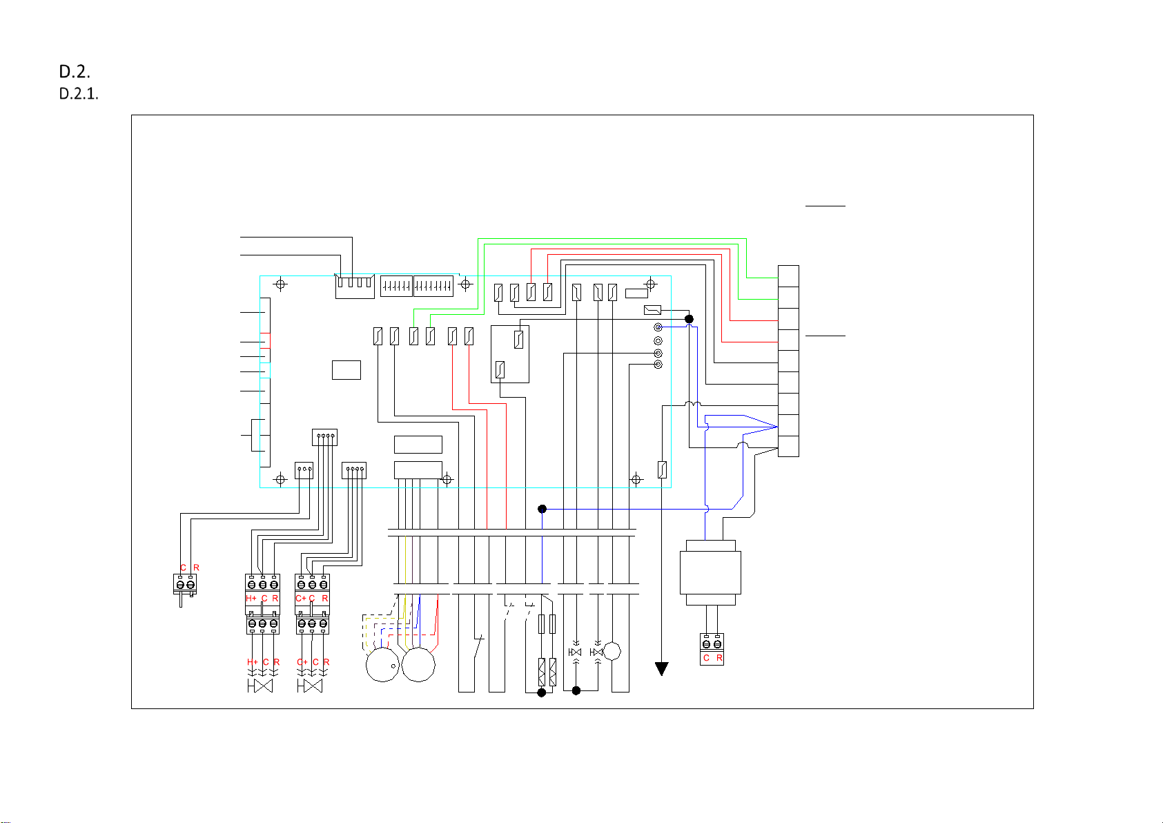
Wiring Diagrams
Standard EC-TOTAL Type Control PCB
NEXT UNIT
CN3
LED display/IR receiver
Renturn sensor (Tr)
2 pipe sensor (Ti1)
chilled /hot water
4-pipe coil circut sensor
(Ti2):hot water
Wired wall pad
Louver stepping motor
connectors
X-DISI
AI1
AI2
AI3
TTL1
CN2
CN1
24Vac Cooling/heating Modulate valve
DA3
DA1
485
A B A B
CPU
DA2
24Vac heating Modulate valve
EC-S1 Unit wiring scheme
GR
GR
RD
RD
WH
WH
YL/GR
BL
BK
24Vac/230Vac
FLOAT
CN4
CN5
EC mot r
S2
WH
GND
BLDC
BLDC
BR
OR
EC motor
VALVE1
AUX2
AUX1
AUX1
S1
ON/OFF
ON/OFF
BL
RD
RD
RY6
EH
GND
L-EH
BK/2.5
WH/2.5
OR
OR
RD
VALVE2
WH
PUMP
FUSE
L1
N
N
N
N
PE
GY
BL
BK
AUX2
BL
TR
Fuse
Fuse
Temp. switch2
Temp. switch1
PUMP
float control switch for pump
Electrical heater
IPA19-DL-EC-S1
DIPA-S1
SW1-5: set the unit address
SW6: set unit type :master or slave
Mode Configuration
SW7=0;SW8=0; unit operates in cooling/heating
PRO
SW7=0;SW8=1; unit operates in cooling/heating w/booster
EH
PRO
SW7=1;SW8=0 ; unit operates in cooling
SW7=1;SW8=1; unit operates in cooling with primary EH
A2 A2 A1 A1
DIPB-S2
SW1: Occupancy contact setting
SW2: Unit configuration setting: 0=2pipe system;
SW3:on/off valve configuration: 0= no valve 1=with valve
G
SW4:preheat setting:0=36C;1=28C
SW5: Fan1(CN4)configuration setting:0=Fan1 OFF;
N
SW6:Fan2(CN5)configuration setting: 0=Fan2 OFF;
L1
L \N----Power supply
VALVE1: 230V on/off valve output;
VALVE2: 230V on/off valve output;
WP: 230V condensate pump output;
AUX1:Voltage free contact; ON:unit in heating mode.
AUX2:Voltage free contact; ON:unit in cooling mode.
ON/OFF:Occupancy contact
CN1~2:Stepping motor output.
CN3:Serial BUS contact
CN4:Fan motor 1 output
CN5:Fan motor 2 output
TTL: Wired wall-pad.
AI1:Return air temperature sensor(Tr)
AI2:Indoor coil temperature sensor1 (Ti1)
AI3:Indoor coil temoeraturesensor 2 (Ti2)
X-DISI----LED receiver output
DA1-24VAC input for modulating valves.
DA2-modulating valve 1 output(0-10V modulating signal).
DA3-modulating valve 2 output(0-10V modulating signal).
1=4-pipe system;
1=Fan1 ON .
1=Fan1 ON .
Page 28 of 71
SK2019 FSTD-SLIM-EC-FLEX-001_01
Page 30

Master-Slave Networking Wiring Diagram
CN1
X-DISI
AI1
AI2
AI3
TTL1
wired wall-pad
4-pipe coil circuit sensor
2-pipe sensor (Ti1):
return air sensor (Tr)
LED display / IR receiver
chilled/hot water
(Ti2):hot water
louver stepping moter
connections
CN2
A B A B
S1
S2
FLOAT
EH2 EH1PR2PR1
AUX2
AUX1
HF
MF
LF
VALVE1
VALVE2
WP
CONNECT
GY
RD
WH
BK
BL
PUMP
L1N
G
A1
A1A2A2PROPRO
TERMINAL
WH
OR
BR
YL
BL
L
N
N
N
N
RY7
BK
BL
YL/GR
WH
WH
RD
RD
GR
GR
485
FUSE
FAN
cap
Electrical heater
1
N
2 3
RD
RD
FAN
cap
float control switch for pump
YL
YL
CN1
X-DISI
AI1
AI2
AI3
TTL1
wired wall-pad
4-pipe coil circuit sensor
2-pipe sensor (Ti1):
return air sensor (Tr)
LED display / IR receiver
chilled/hot water
(Ti2):hot water
louver stepping moter
connections
CN2
A B A B
S1
S2
FLOAT
EH2 EH1PR2 PR1
AUX2
AUX1
HF
MF
LF
VALVE1
VALVE2
WP
CONNECT
GY
RD
WH
BK
BL
PUMP
L1N
G
A1
A1A2A2
PROPRO
TERMINAL
WH
OR
BR
YL
BL
L
N
N
N
N
RY7
BK
BL
YL/GR
WH
WH
RD
RD
GR
GR
485
FUSE
FAN
cap
Electrical heater
1
N
2 3
RD
RD
FAN
cap
float control switch for pump
YL
YL
CN1
X-DISI
AI1
AI2
AI3
TTL1
wired wall-pad
4-pipe coil circuit sensor
2-pipe sensor (Ti1):
return air sensor (Tr)
LED display / IR receiver
chilled/hot water
(Ti2):hot water
louver stepping moter
connections
CN2
A B A B
S1
S2
FLOAT
EH2 EH1PR2PR1
AUX2
AUX1
HF
MF
LF
VALVE1
VALVE2
WP
CONNECT
GY
RD
WH
BK
BL
PUMP
L1
N
GA1
A1A2A2
PROPRO
TERMINAL
WH
OR
BR
YL
BL
L
N
N
N
N
RY7
BK
BL
YL/GR
WH
WH
RD
RD
GR
GR
485
FUSE
FAN
cap
Electrical heater
1
N
2 3
RD
RD
FAN
cap
float control switch for pump
YL
YL
B
A
Page 29 of 71
SK2019 FSTD-SLIM-EC-FLEX-001_01
Page 31

Page 30 of 71
SK2019 FSTD-SLIM-EC-FLEX-001_01
Configuration Settings
Note: 0 = OFF
1 = ON
SW1-SW5 Network address
setting
DIPA-S1
DIPB-S2
SW5/SW6 Fan Qty setting
SW5=0 Single fan application
SW6=1
SW5=1 Twin fans application
SW6=1
SW7/SW8 Operating mode
SW7=0 Cooling and heating modes available
SW8=0
SW7=0 Cooling and heating modes available,
SW8=1 with EH functioning as booster
SW7=1 Cooling mode only available
SW8=0
SW7=1 Cooling and heating modes available,
SW8=1 with EH functioning as primary
Master / Slave setting
SW6=1 Master
SW6=0 Slave
Preheat temperature setting
SW4=1 28
o
C
SW4=0 36
o
C
230VAC on/off valve setting
SW3=1 With valve
SW3=0 Without valve
2-pipe/4-pipe system configuration
SW2=1 4-pipe system
SW2=0
2-pipe system
PRO contact setting
SW1=1 Window contact (remote on/off)
When PROs closed for 10 minutes, unit
enters standby mode.
When PROs opened, unit resumes
operation.
SW1=0 Economy contact
When PROs closed, dead-band condition
is increased from “Tr=Ts+/-1” to “Tr=Ts+/-
4”.
Page 32

Page 31 of 71
SK2019 FSTD-SLIM-EC-FLEX-001_01
Fan Coil Unit ON/OFF
There are 3 ways to turn the system on or off:
a) By the ON/OFF button on the remote handset or wired wall pad;
b) By the programmable timer on the handset or wired wall pad.
c) By the manual control button on fan coil unit.
Auto Restart
The system uses a non-volatile memory to save the present operation parameters when the system is turned off
or in case of system failure or cessation of power supply.
The restored parameter data-set depends on the type of user interface.
a) Handset only user interface:
When the power ON signal is received by the fan coil unit and no wired wall-pad is installed, the Mode, Fan Speed,
Set temperature will be the same as the handset setting before the last power OFF.
b) Wall-pad only OR wall-pad and handset user interface:
When the power ON signal is received by the fan coil unit and a wired wall-pad is installed, the Mode, Fan Speed,
Set temperature and Timer ON/OFF weekly program will be the same as the wall pad setting before the last power
OFF.
Page 33

Page 32 of 71
SK2019 FSTD-SLIM-EC-FLEX-001_01
Control Logics for 2-Pipe System
With Valve Configuration
COOL MODE
a) MTV2, AUX1 and electric heater are always off.
b) If Tr ≥ Ts + 1ºC (or + 4ºC if economy contact is activated), then cool operation is activated and MTV1 and AUX2 are turned
on. Indoor fan runs at set speed.
c) If Tr < Ts, then cool operation is terminated and MTV1 and AUX2 are turned off. Indoor fan runs at set speed.
d) The range of Ts is 16 - 30ºC
e) Indoor fan speed can be adjusted to low, medium, high and auto.
f) When turned on, MTV1 requires 30 seconds before it is fully open.
g) When turned off, MTV1 requires 120 seconds before it is fully closed.
h) When the unit is turned off, the indoor fan will shut down after 5 seconds.
LOW TEMPERATURE PROTECTION OF INDOOR COIL
a) If Ti1 ≤ 2 ºC for 2 minutes, then MTV1 and AUX2 are turned off. If indoor fan is set for low speed, then it will run at
medium speed. If it is set at medium or high speed, then it will keep running at the same speed.
b) If Ti1 ≥ 5ºC for 2 minutes, then MTV1 and AUX2 are turned on. Indoor fan runs at set speed.
FAN MODE
a) Indoor fan runs at the set speed while heater, MTV1, MTV2, AUX1 and AUX2 are turned off.
b) Indoor fan speed can be adjusted to low, medium and high.
HEAT MODE
Heat mode without electrical heater
a) MTV2, AUX2 and electric heater are always off.
b) If Tr ≤ Ts - 1 ºC (or - 4ºC if economy contact is activated), then heat operation is activated and MTV1 and AUX1 are turned
on. Indoor fan runs at the set speed.
c) If Tr > Ts, then heat operation is terminated and MTV1 and AUX1 are turned off. Indoor fan runs at Modbus 310000
setting.
d) The range of Ts is 16 - 30ºC.
e) Indoor fan speed can be adjusted to low, medium, high and auto.
f) When turned on, MTV1 requires 30 seconds before it is fully open.
g) When turned off, MTV1 requires 120 seconds before it is fully closed.
Heat mode with electrical heater as booster
a) MTV2 and AUX2 are always off.
b) If Tr ≤ Ts - 1ºC (or - 4ºC if economy contact is activated), then heat operation is activated and MTV1 and AUX1 are turned
on. Indoor fan runs at the set speed.
c) If Tr > Ts, then heat operation is terminated and MTV1 and AUX1 are turned off. Indoor fan runs at Modbus 310000
setting.
d) If Ti1 < 40ºC, then the electrical heater is turned on. If 40ºC ≤ Ti1 < 45ºC, then the electrical heater maintains its original
state. If Ti1 ≥ 45ºC, then the electrical heater is turned off.
e) The range of Ts is 16 - 30ºC
f) Indoor fan speed can be adjusted to low, medium, high and auto.
g) When turned on, MTV1 requires 30 seconds before it is fully open.
h) When turned off, MTV1 requires 120 seconds before it is fully closed.
Page 34

Page 33 of 71
SK2019 FSTD-SLIM-EC-FLEX-001_01
Heat mode with electrical heater as primary heat source
a) MTV1, MTV2, and AUX2 are always off
b) If Ti2 ≤ 30ºC (or Ti2 is damaged or disconnected), AND if Tr ≤ Ts-1ºC (or -4ºC if economy contact is activated), heat
operation is activated, electrical heater and AUX1 are turned on. Indoor fan runs at set speed.
c) If Tr > Ts, then heat operation is terminated, Electrical heater and AUX 1 are turned off. Indoor fan runs at Modbus
310000 setting.
d) The range of Ts is 16-30 ºC
e) Indoor fan speed can be adjusted to low, medium, high and auto.
Over-heat protection of indoor coil in heat mode
a) If Ti1 ≥ 75 ºC, then MTV1, AUX2 and EH are turned off, indoor fan runs at high speed, even in standby mode.
b) If Ti1 < 70 ºC, then unit will maintain its original state.
c) If the indoor coil temperature sensor is damaged, the protection mode will be overridden and the pre-heat and post-heat
set times will be used instead.
PRE-HEAT
Pre-heat without electrical heater
a) If Ti1 < 36ºC [or < 28ºC is selected by DIPB-S2 position SW4], then MTV1 and AUX1 are turned on, indoor fan runs at
Modbus 310000 setting.
b) If Ti1 ≥ 38ºC [or ≥ 30ºC is selected by DIPB-S2 position SW4], then MTV1 and AUX1 are turned on, indoor fan runs at set
speed.
c) If the indoor coil temperature sensor is damaged, then the pre-heat time is set for 2 minutes. Indoor fan runs at set
speed.
Pre-heat with electrical heater
a) If the indoor fan speed ≥ at Modbus 310000 setting, then the electrical heater will turn on.
POST-HEAT
Post-heat without electrical heater
a) If Ti1 ≥ 38ºC, then MTV1 and AUX 1 are off, then indoor fan continues to run at set speed.
b) If 36ºC ≤ Ti1 ≤ 38ºC, then MTV1 and AUX1 are turned off. Then indoor fan maintains its original state.
c) If Ti1 < 36ºC, then MTV1 and AUX1 are turned off. Then indoor fan is turned OFF.
d) If the indoor coil temperature sensor is damaged, then the post-heat time is set for 3 minutes. Indoor fan runs at set
speed.
Post-heat with electrical heater
a) Indoor fan will run at Modbus 310000 setting before the unit turns off for 20 seconds.
Over-heat protection of indoor coil in post-heat
a) If Ti1 ≥ 75ºC, then MTV1 and AUX1 are turned off. Indoor fan remains on and runs at high speed.
b) If Ti1 < 70ºC, then MTV1 and AUX1 are turned on. Indoor fan remains on and runs at set speed.
c) If the indoor coil temperature sensor is damaged, then the protection mode will be overridden and the unit will work
according to the pre-heat and post-heat program.
DEHUMIDIFICATION MODE
a) MTV2, AUX1 and heater are always off.
b) If Tr ≥ 25ºC, then MTV1 and AUX2 will be ON for 3 minutes, and then OFF for 4 minutes.
c) If 16ºC ≤ Tr < 25ºC, then MTV1 and AUX2 will be ON for 3 minutes, and then OFF for 6 minutes.
d) If Tr < 16ºC, then MTV1 and AUX2 will be turned off for 4 minutes.
e) At the end of the above dehumidification cycle, the system will decide the next dehumidification control option. Indoor
fan will run at low speed throughout the dehumidification process.
Page 35

Page 34 of 71
SK2019 FSTD-SLIM-EC-FLEX-001_01
AUTOMODE
Auto cool/heat/heat with electric heater as booster
Every time the unit is turned on, MTV1 is on, AUX1, AUX2 and fan are off. MTV2 and heater are always off.
After 120secs, the subsequent operation mode is decided according to the following programs:
a) If the coil temperature sensor (Ti1) ≥ 36ºC, then MTV1, AUX1 and fan turn on or off according to HEAT mode.
b) If Ti1 < 36ºC, then MTV1, then AUX2 and fan turn on or off according to COOL mode.
Unit remains in AUTO COOL or AUTO HEAT mode throughout the operating cycle until the user changes the mode manually or
restarts the unit.
Should the Ti1 sensor be damaged, auto mode will not function.
Auto heat with electric heater as primary heat source / all configuration auto changeover
If current running mode is auto cool mode, then the control Logics will change over to auto heat mode when all the following
conditions are met:
a) Ts -Tr ≥ 1.0°C (or 4 ºC if economy contact is activated)
b) MTV1 has stop ≥ 10 min.
If current running mode is auto heat mode, then the control Logics will change over to auto cool mode when all the following
conditions are met:
a) Tr -Ts ≥ 1.0°C (or 4 ºC if economy contact is activated)
b) MTV1 has stop ≥ 10 min.
Note: Auto cool or auto heat operation are the same as cool or heat mode respectively.
Page 36

Page 35 of 71
SK2019 FSTD-SLIM-EC-FLEX-001_01
Without Valve Configuration
COOL MODE
a) Electric heater, AUX1, MTV1 and MTV2 are always off.
b) If Tr ≥ Ts + 1ºC (or + 4ºC if economy contact is activated), then cool operation is activated and AUX2 is turned on. Indoor
fan runs at set speed.
c) If Tr < Ts, then cool operation is terminated and AUX2 is turned off. Indoor fan runs at Modbus 310000 setting.
d) The range of Ts is 16 - 30ºC
e) Indoor fan speed can be adjusted to low, medium, high and auto.
Note: When the unit is turned off, the indoor fan shut down after 5 seconds.
LOW TEMPERATURE PROTECTION OF INDOOR COIL
a) If Ti1 ≤ 2ºC for 2 minutes, then AUX2 is turned off. If low speed is selected via user interface, then indoor fan runs at
medium speed. If medium or high speed is selected via user interface, then indoor fan runs at set speed.
b) If Ti1 ≥ 5ºC for 2 minutes, then AUX2 is turned on. Indoor fan runs at set speed.
FAN MODE
a) Indoor fan runs at the set speed while heater, AUX1, AUX2, MTV1 and MTV2 are turned off.
b) Indoor fan speed can be adjusted to low, medium and high.
HEAT MODE
Heat mode without electrical heater
a) MTV1, MTV2, AUX2 and heater are always off.
b) If Tr ≤ Ts - 1ºC (or - 4ºC if economy contact is activated), then heat operation is activated and AUX1 is turned on. Indoor
fan runs at the set speed.
c) If Tr > Ts, then heat operation is terminated and AUX1 is turned off. Indoor fan runs at 200rpm.
d) The range of Ts is 16 - 30ºC.
e) Indoor fan speed can be adjusted to low, medium, high and auto.
Heat mode with electrical heater as booster
a) MTV1, MTV2 and AUX2 are always off.
b) If Tr ≤ Ts - 1ºC (or - 4ºC if economy contact is activated), then heat operation is activated and AUX1 is turned on. Indoor
fan runs at the set speed.
c) If Tr > Ts, then heat operation is terminated and AUX1 is turned off. Indoor fan runs at Modbus 310000 setting.
d) If Ti1 < 40ºC, then the electrical heater is turned on. If 40ºC ≤ Ti1 < 45ºC, then the electrical heater maintains its original
state. If Ti1 ≥ 45ºC, then the electrical heater is turned off.
e) The range of Ts is 16 - 30ºC.
f) Indoor fan speed can be adjusted to low, medium, high and auto.
PRE-HEAT
Pre-heat with electrical heater
a) Indoor fan will start after the electrical heater has been turned on for 10seconds.
POST-HEAT
Post-heat with and without electrical heater
a) AUX1 is off. Electrical heater is turned off.
b) Indoor fan will stop after the unit has been turned off for 20secs.
Page 37

Page 36 of 71
SK2019 FSTD-SLIM-EC-FLEX-001_01
Over heat protection of indoor coil in post-heat
a) If Ti1 ≥ 75ºC, then AUX1 is turned off, indoor fan remains on and runs at high speed.
b) If Ti1 < 70ºC, then AUX1 is turned on, indoor fan remains on and runs at set speed.
c) If the indoor coil temperature sensor is damaged, then the protection mode will be overridden and the unit will work
according to the pre-heat and post-heat program.
DEHUMIDIFICATION MODE
a) MTV1, MTV2, AUX1 and heater are always off.
b) If Tr ≥ 25ºC, then indoor fan and AUX2 will be ON for 3 minutes, and then OFF for 4 minutes.
c) If 16ºC ≤ Tr < 25ºC, then indoor fan and AUX2 will be ON for 3 minutes, and then OFF for 6 minutes.
d) If Tr < 16ºC, then indoor fan and AUX2 will be turned off for 4 minutes.
e) At the end of the above dehumidification cycle, the system will decide the next dehumidification control option. Indoor
fan will run at low speed throughout the dehumidification process.
AUTOMODE
Not available
Page 38

Page 37 of 71
SK2019 FSTD-SLIM-EC-FLEX-001_01
Control Logics For 4-Pipe System
Note: 4-pipe system must always be equipped with 2 valves.
COOL MODE
a) MTV2, AUX1 and Electrical Heater are always off.
b) If Tr ≥ Ts + 1ºC (or + 4ºC if economy contact is activated), then cool operation is activated, MTV1 and AUX2 are turned on.
Indoor fan runs at set speed.
c) If Tr < Ts, then cool operation is terminated, MTV1 and AUX2 are turned off. Indoor fan runs at set speed.
d) The range of Ts is 16 - 30ºC
e) Indoor fan speed can be adjusted to low, medium, high and auto.
f) When turned on, MTV1 requires 30 seconds before it is fully open.
g) When turned off, MTV1 requires 120 seconds before it is fully closed.
h) When the unit is turned off, the indoor fan will shut down after 5 seconds.
LOW TEMPERATURE PROTECTION OF INDOOR COIL
a) If Ti1 ≤ 2ºC for 2 minutes, then MTV1 and AUX2 are turned off. If indoor fan is set for low speed, then it will run at
medium speed. If it is set at medium or high speed, then it will keep running at the same speed.
b) If Ti1 ≥ 5ºC for 2 minutes, then MTV1 and AUX2 are turned on. Indoor fan runs at set speed.
FAN MODE
a) Indoor fan runs at the set speed while heater, MTV1, MTV2, AUX1 and AUX2 are turned off.
b) Indoor fan speed can be adjusted to low, medium and high.
HEAT MODE
Without Electrical Heater
a) MTV1, AUX2 and are heater always off.
b) If Tr ≤ Ts - 1ºC (or - 4ºC if economy contact is activated), then heat operation is activated, MTV2 and AUX1 are turned on.
Indoor fan runs at the set speed.
c) If Tr > Ts, then heat operation is terminated, MTV2 and AUX1 are turned off. Indoor fan runs at Modbus 310000 setting.
d) The range of Ts is 16 - 30ºC.
e) Indoor fan speed can be adjusted to low, medium, high and auto.
f) When turned on, MTV2 requires 30 seconds before it is fully open.
g) When turned off, MTV2 requires 120 seconds before it is fully closed.
With Electrical Heater as Booster
a) MTV1 and AUX2 are always off.
b) If Tr ≤ Ts - 1ºC (or - 4ºC if economy contact is activated), then heat operation is activated, MTV2 and AUX1 are turned on.
Indoor fan runs at the set speed.
c) If Tr > Ts, then heat operation is terminated, MTV2 and AUX1 are turned off. Indoor fan runs at Modbus 310000 setting.
d) If Ti2 < 40ºC, then the electrical heater is turned on. If 40ºC ≤ Ti2 < 45ºC, then the electrical heater maintains its original
state. If Ti2 ≥ 45ºC, then the electrical heater is turned off.
e) The range of Ts is 16 - 30ºC
f) Indoor fan speed can be adjusted to low, medium, high and auto.
g) When turned on, MTV2 requires 30 seconds before it is fully open.
h) When turned off, MTV2 requires 120 seconds before it is full closed.
Page 39

Page 38 of 71
SK2019 FSTD-SLIM-EC-FLEX-001_01
PRE-HEAT
Without Electrical Heater
a) If Ti2 < 36ºC [or 28ºC depends on DIP setting], then MTV2 and AUX1 are on, then indoor fan remains off.
b) If Ti2 ≥ 38ºC [or 30ºC depends on DIP setting], then MTV2 and AUX1 are on, then indoor fan runs at set speed.
c) If indoor coil temperature sensor is damaged, then pre-heat time is set for 2 minutes and indoor fan runs at set speed.
With Electrical Heater
a) If indoor fan speed ≥ Modbus 310000 setting, then the electrical heater is turned on.
POST HEAT
Without Electrical Heater
a) If Ti2 ≥ 38ºC, then MTV2 and AUX 1 are turned off. Indoor fan continues to run at set speed.
b) If 36ºC ≤ Ti2 ≤ 38ºC, then MTV2and AUX1 are turned off. Indoor fan maintains its original state.
c) If Ti2 < 36ºC, then MTV2 and AUX1 are turned off. Indoor fan runs at 200 rpm.
d) If the indoor coil temperature coil is damaged, then post-heat time is set for 3 minutes. Indoor fan runs at set speed.
With Electrical Heater
a) Indoor fan will shut down after the unit has been turned off for 20 seconds.
OVER HEAT PROTECTION OF INDOOR COIL
a) If Ti2 ≥ 75ºC, then MTV2 and AUX1 are turned off, indoor fan remains on and runs at high speed.
b) If Ti2 < 70ºC, then MTV2 and AUX1 are turned on, indoor fan remains on and runs at set speed.
c) If the indoor coil temperature sensor is damaged, then the protection mode will be overridden and the unit will work
according to the pre-heat and post heat set times.
DEHUMIDIFICATION MODE
a) MTV2, AUX1 and heater are always off.
b) If Tr ≥ 25ºC, then MTV1 and AUX2 will be ON for 3 minutes, and then OFF for 4 minutes.
c) If 16ºC ≤ Tr < 25ºC, then MTV1 and AUX2 will be ON for 3 minutes, and then OFF for 6 minutes.
d) If Tr < 16ºC, then MTV1 and AUX2 will be turned off for 4 minutes.
e) At the end of the above dehumidification cycle, the system will decide the next dehumidification control option. Indoor
fan will run at low speed throughout the dehumidification process.
AUTOMODE
a) If the current running mode is AUTO COOL mode, it will change over to AUTO HEAT mode when all the following
conditions are met:
i. Ts – Tr ≥ 1ºC (or - 4ºC if economy contact is activated)
ii. MTV1 has closed ≥ 10 min.
b) If the current running mode is AUTO HEAT mode, it will change over to AUTO COOL mode when all the following
conditions are met:
iii. Tr – Ts ≥ 1ºC (or + 4ºC if economy contact is activated)
iv. MTV2 has closed ≥ 10 min.
Note: AUTO COOL or AUTO HEAT operations are the same as COOL or HEAT mode respectively.
Page 40
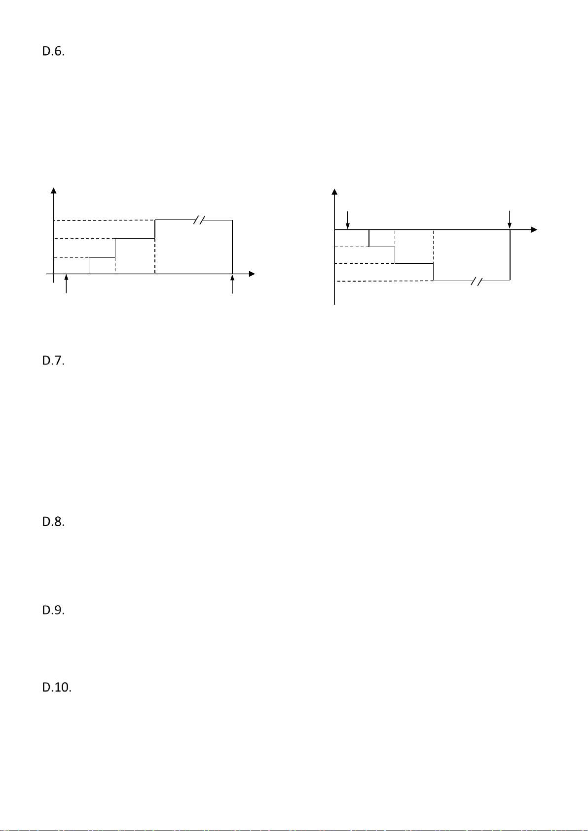
Page 39 of 71
SK2019 FSTD-SLIM-EC-FLEX-001_01
Sleep Mode
a) The sleep mode can only be set when the unit is in cool mode or heat mode.
b) If the sleep mode is activated when the unit is in cool mode, then the indoor fan will run at low speed and Ts will increase
by 2ºC over 2 hours.
c) If the sleep mode is activated when the unit is in heat mode, then the indoor fan will run at set speed and Ts will decrease
by 2ºC over 2 hours.
d) Changing the mode of operation will cancel the sleep mode.
The cool mode sleep profile is:
The heat mode sleep profile is:
Auto Fan Speed
COOL MODE
HEAT MODE
Fan speed cannot change until it has run for more than 30
seconds.
Fan speed cannot change until it has run for more than 30
seconds.
After 30 seconds the fan speed is modulated according to the difference between the room temperature and the set
temperature. The controller adjusts the motor signal input from 0 to 5VDC by PID calculation every 10 seconds. The air flow is
adjusted from 15% to100%.
Modulating Valve Control Under Energy Saving Mode
If the modulating valve is used, the water flow is adjusted from Modbus 310015 setting to 100% according to the room
temperature and set temperature. The controller adjusts the modulating valve signal input from Modbus 310015 setting to
10VDC by PID calculation for time interval according to Modbus 310007 setting.
Buzzer
If a command is received by the fan coil unit, the master unit will respond with 2 beeps for each setting, while the slave unit
will respond with 1 beep.
Auto Restart
The system uses non-volatile memory to save the present operation parameters when system is turned off or in case of
system failure or cessation of power supply. Operation parameters are mode, set temperature and the fan speed. When
power supply resumes or the system is switched on again, the same operations as previously set will function.
Hour
Sleep on
0.5
1.0
2.0
Sleep off
Set temperature
Ts
Ts+0.5
Ts+1.0
Ts+2.0
Hour
Sleep on
0.5
1.0
2.0
Sleep off
Set temperature
Ts
Ts -2.0
Ts -1.0
Ts -0.5
Page 41

Page 40 of 71
SK2019 FSTD-SLIM-EC-FLEX-001_01
On/Off Switch On The Front Panel
a) This is a TACT switch to select Cool→Heat→Off operation mode.
b) In COOL mode, the set temperature of the system is 24ºC with auto fan speed. There are no timer and sleep modes.
c) In HEAT mode, the set temperature of the system is 24ºC with auto fan speed. There are no timer and sleep modes.
d) Master unit that does not use a wall pad will globally broadcast.
Electric Heater Safety Switch
a) Before the electrical heater is turned on, the EH safety switch must be closed and EC motor RPM must be more than
Modbus 310000 setting.
b) When electrical heater is ON, electrical heater safety switch is opened for ≥ 1 second or EC motor RPM is lower than
Modbus 310000 setting, EH will be turned off immediately and report an error and fan speed is changed to high speed.
c) Once the contact is returned to the closed ≥ 180 seconds, reset the error and the heater will start again.
d) When the EH safety switch is opened ≥ 3 times within 60 minutes the heater is not allowed to start anymore.
e) Turn off the unit to reset the fault, provided that the switch has returned to the closed position.
Low Temperature Protection of Indoor Coil in Winter
This is frost protection for when the unit is off to prevent water in the coil and room from freezing.
If Unit with SW2=0 (2-pipe system), is in Standby Mode
If Tr ≦ 2 ºC for 2 minutes
1. MTV1 is turned ON
2. AUX1 is closed
3. DA2 is 10 VDC
4. If Ti1 < 5ºC for 2 minutes EH (if present) is switched on
5. Indoor fan is turned on at low speed
If Tr ≧ 5ºC for 2 minutes
1. MTV1 is turned OFF
2. AUX1 is open
3. DA2 is 0 VDC
4. Electric Heater is turned OFF
5. Indoor fan Switched OFF
If Unit with SW2=1(4-pipe system), is in Standby Mode
If Tr ≦ 2 ºC for 2 minutes
1. MTV2 is turned ON
2. AUX1 is closed
3. DA3 is 10 VDC
4. If Ti2 < 5ºC for 2 minutes EH (if present) is switched ON
5. Indoor fan is turned on at low speed
If Tr ≧ 5ºC for 2 minutes
1. MTV2 is OFF
2. AUX1 is open
3. DA3 is 0 VDC
4. Electric Heater is turned OFF
5. Indoor fan Switched OFF
NOTE
When button pressing is effective, the master unit buzzer will beep twice and the slave unit will beep once.
Page 42

Page 41 of 71
SK2019 FSTD-SLIM-EC-FLEX-001_01
Networking System
Master-Slave Network
The control PCB can be set either as a master unit or slave unit.
Mater Unit Function
a) The master unit sends data regarding its setting to the slave unit.
b) The master unit settings are unit ON/OFF, Mode, Fan Speed, Timer, Clock, Set Temperature, Louver Function, and Sleep
Function for handset operation.
c) The master unit settings are unit ON/OFF, Mode, Fan Speed, Timer, Clock, Set Temperature, Louver Function, and Sleep
Function for wall pad operation.
Slave Unit Function
a) The slave unit receives data regarding its settings from the master unit.
b) The slave unit is allowed to change to a locally desired setting by local controller as long as there are no subsequent
changes to the settings of the master unit.
c) The slave units can be set individually for timer ON/OFF function by handset or wall pad. The handset cannot override
the wall pad timer and clock setting.
Master Unit Control Settings
The control PCB can receive data from both wireless Infrared handset and wired wall pad.
Using Remote Control Handset to Set Master Control Unit:
1. Connect all the units PCBs according to the wire color and type of connector.
2. Select the master unit by setting DIPA-S1 SW6 to ON (=1) in the PCB.
3. Ensure the DIPA-S1 SW6 is set to OFF (=0) in the PCB on each slave unit.
4. Switch on the units by connecting the main power supply.
5. Using the handset, set the operation parameters for the master unit which will automatically send the settings to the
slave unit.
6. Master unit will beep twice confirming receipt of commands while the slave unit will beep once.
Using Wall pad to Set Master Control Unit:
1. Connect all the units PCBs according to the wire color and type of connector.
2. Select the master unit by setting DIPA-S1 SW6 to ON (=1) in the PCB.
3. Ensure the DIPA-S1 SW6 is set to OFF (=0) in the PCB on each slave unit.
4. Provide each slave unit with an addressable code by configuring SW1 – SW5 of DIPA-S1 according to the DIP switch
setting table.
5. Switch on the units by connecting the main power supply.
6. Using the wall pad set the operation parameters for the master unit which will send the setting to the slave units by
Global-control communication or Addressable communication methods.
7. Master unit will beep twice confirming receipt of commands while the slave unit will beep once.
Page 43

Page 42 of 71
SK2019 FSTD-SLIM-EC-FLEX-001_01
Master-Slave Network Setup
1) Disconnect the communication plug from the control box
2) Communication plug
A, B, A, B is printed on the main PCB. When you connect the wires, please ensure connection of A to A and B to B.
3) Connection wire
i. If the total length of wire is more than 1000m, please use shielded wire in order to protect the signal transmission.
ii. Complete wire connection
First unit
Middle unit
Last unit
Page 44

Page 43 of 71
SK2019 FSTD-SLIM-EC-FLEX-001_01
iii. Wire connection check
a) After the wire connection is completed, please check that the wire colours correspond.
b) Check the wire contact by using a multimeter.
c) Check 1 and 2, 3 and 4, 5 and 6 to be sure the connections are correct.
d) If the resistance between two wire contacts is too high, please check and reconnect the wire contacts.
4) Reconnect the communication plug to the control box
First unit
Middle unit
Last unit
1st
contact
2nd
contact
3rd
contact
4th
contact
5th
contact
6th
contact
Page 45

Page 44 of 71
SK2019 FSTD-SLIM-EC-FLEX-001_01
Master-Slave Communication Method
There are two modes for the master-slave structure.
Global Control communication
The master unit will broadcast the settings to all slave units. During normal operation, slave units can receive commands from
its wireless handset and wall pad control panel. Upon receiving the master global commands, all slave unit settings will be
replaced by the master settings.
Addressable communication
The master controller must be the LCD wall pad. Slave unit parameters are set as usual. Upon receiving the control commands
from the master unit, the addressed slave unit settings will be replaced by the master settings.
DIPA-S1 address setting: ON=1, OFF=0.
DIPA-S1 SW6
DIPA-S1 SW5
DIPA-S1 SW4
DIPA-S1 SW3
DIPA-S1 SW2
DIPA-S1 SW1
Unit No.
Remark
1 0 0 0 0 0 01
Master 0 0 0 0 0 1
02
Slave
0 0 0 0 1 0 03
Slave
0 0 0 0 1 1 04
Slave 0 0 0 1 0 0
05
Slave 0 0 0 1 0 1
06
Slave 0 0 0 1 1 0
07
Slave
0 0 0 1 1 1 08
Slave
0 0 1 0 0 0 09
Slave
0 0 1 0 0 1 10
Slave
0 0 1 0 1 0 11
Slave
0 0 1 0 1 1 12
Slave
0 0 1 1 0 0 13
Slave 0 0 1 1 0 1
14
Slave 0 0 1 1 1 0
15
Slave 0 0 1 1 1 1
16
Slave 0 1 0 0 0 0
17
Slave 0 1 0 0 0 1
18
Slave 0 1 0 0 1 0
19
Slave 0 1 0 0 1 1
20
Slave
0 1 0 1 0 0 21
Slave
0 1 0 1 0 1 22
Slave
0 1 0 1 1 0 23
Slave
0 1 0 1 1 1 24
Slave
0 1 1 0 0 0 25
Slave
0 1 1 0 0 1 26
Slave 0 1 1 0 1 0
27
Slave
0 1 1 0 1 1 28
Slave
0 1 1 1 0 0 29
Slave 0 1 1 1 0 1
30
Slave 0 1 1 1 1 0
31
Slave 0 1 1 1 1 1
32
Slave
If the master unit is equipped with a wireless handset only, it can only use the Global-Control communication method. If it is
equipped with a wall pad, it can use both communication methods.
Page 46
Page 45 of 71
SK2019 FSTD-SLIM-EC-FLEX-001_01
Open Modbus protocol
Transfer Mode: RTU, BAUD Rate: 9600bps, 8 data bit, 1 stop bit, None parity bit
The communications require a delay of 80ms between reading an answer and sending the next command. All temperatures
are equal to reading data*10 accuracy: 0.1 degree C.
Supported Functions:
Function Code
Function Description
01(01H)
Read Coils
02(02H)
Read Discrete Inputs
03(03H)
Read Holding Registers
04(04H)
Read Input Registers
05(05H)
Write Single Coil
06(06H)
Write Single Register
15(0FH)
Write Multiple Coils
16(10H)
Write Multiple Registers
255(FFH)
Extended Commands which are used to test unit
Valid Error code table:
Error code
Description
Definition
01 (01H)
Invalid commands
Received commands beyond valid commands
02 (02H)
Invalid data address
Data addresses beyond valid data address
03 (03H)
Invalid data
Data beyond definition range
04 (04H)
Write data not successful
Write data did not succeed
Coils table:
Description
Address
Type*
Remark
Unit ON/OFF
100000
R/W
Sleep mode
100001
R/W
Louver swing
100002
R/W
Reserved
100003 to 100015
Discrete table:
Description
Address
Type*
Remark
MTV1
200000
R MTV2
200001
R AUX1
200002
R
AUX2
200003
R
Condensate pump
200004
N/A Electrical heater
200005
R Wired wall pad
200006
R PRO
200007
R Float switch
200008
R Reserved
200009
R EH safety switch
200010
R Unit ON/OFF status
200011
R
Testing purpose only.
* R = read only, W = write only, R/W = read and write.
Page 47

Page 46 of 71
SK2019 FSTD-SLIM-EC-FLEX-001_01
Holding Register table:
Description
Address
Type*
Remark
Mode setting
300000
R/W
Cooling mode = 01(H)
Humidify mode = 02(H)
Fan mode = 04(H)
Heating mode = 08(H)
Auto mode = 10(H)
Fan speed setting
300001
R/W
Low speed = 04(H)
Medium speed = 02(H)
High speed = 01(H)
Auto fan speed = 07(H)
Louver swing setting
300002
R/W
Position 1 = 01(H)
Position 2 = 02(H)
Position 3 = 03(H)
Position 4 = 04(H)
Auto = 0F(H)
Stop = 00(H)
Setting temperature
300003
R/W
16~30 degree C (actual*10 format)
Address setting
300004
R
Set by dip-switch, reading only
Reset
300005
W
=0x33 reset error
Week
300006
W
Calibration wired wall pad and set timer
function
Hour
300007
W
Calibration wired wall pad and set timer
function
Minute
300008
W
Calibration wired wall pad and set timer
function
Second
300009
W
Calibration wired wall pad and set timer
function
Hours in Timer on
300010
R/W
Timer ON
Minute in Timer on
300011
R/W
Timer ON
Hours in Timer off
300012
R/W
Timer OFF
Minute in Timer off
300013
R/W
Timer OFF
Icon of Timer ON or OFF
300014
R/W
BIT0 = Icon of Timer ON
BIT1 = Icon of Timer OFF
1 = enable
0 = disable
Minimum valve opening
position
300015
R/W
Default: 25% (2.5 VDC)
Super low speed rpm
310000
R/W
200~1500
Low speed rpm
310001
R/W
200~1500
Medium speed rpm
310002
R/W
200~1500
High speed rpm
310003
R/W
200~1500
RPM setting
310004
R/W
0~2000 (used to test,0 = disable)
Temperature sampling time
310005
R/W
2~100, default:5S
Factor of auto fan speed
310006
R/W
2~150, default:20
Factor of modulating valve
310007
R/W
2~250, default:150
* R = read only, W = write only, R/W = read and write.
Page 48

Page 47 of 71
SK2019 FSTD-SLIM-EC-FLEX-001_01
Input Register table:
Description
Address
Type*
Remark
Dip switch 1 status
400000
R
Dip switch 2 status
400001
R
Room temperature sensor
400002
R
Ti1 temperature sensor
400003
R
Ti2 temperature sensor
400004
R
Error code
400005
R
Bit0 = Room temperature sensor error
Bit1 = Ti1 temperature sensor error
Bit2 = Ti2 temperature sensor error
Bit3 = Float switch error
Bit4 = Indoor coil low temperature protection
Bit5 = Indoor coil over heat protection
Bit6 = Reserved
Bit7 = Electrical heater failure
Bit8 = Motor1 Error
Bit9 = Motor2 Error
Bit10 = System parameters error
Bit11 = Reserved
Bit12 = Reserved
Bit13 = Reserved
Bit14 = Reserved
Bit15 = Reserved
Fan speed status
400006
R
Low = 04(H)
Medium = 02(H)
High = 01(H)
Mode status
400007
R
Cooling mode = 01(H)
Dehumidify mode = 02(H)
Fan mode = 04(H)
Heating = 08(H)
Setting temperature status
400008
R
Testing only
Room temperature in wall
pad status
400009
R
Room temperature in main
PCB status
400010
R
Unit type
400011
R
4-pipe = 03, 2-pipe = 02
This setting is configured by dip switch
EC motor 1# RPM
400012
R
EC motor 2# RPM
400013
R
DA2 signal
400014
R
DA3 signal
400015
R
* R = read only, W = write only, R/W = read and write.
Remark:
The above protocol address is in Base 0.
Page 49

Page 48 of 71
SK2019 FSTD-SLIM-EC-FLEX-001_01
Control Specifications: Flexible Function PCB – FLEXI Type Control
Features
a) Integrated fan relays for zone control applications.
b) ON/OFF thermostat input and low-voltage modulating fan speed input flexibility.
c) Simple error diagnostic and LED error display.
I/O Port Definitions
I/O
Code
2-Pipe
4-Pipe
Analogue input
Coil temperature sensor
AI1
Cooling / heating coil sensor
(Ti1)
Cooling only coil sensor
(Ti1)
Voltage input
High fan speed
H
230 VAC input signals from wired thermostat
Medium fan speed
M
Low fan speed
L
EH signal
EH
230 VAC input signals from wired thermostat
Phase
L1
External 230VAC power supply connection to the PCB
Neutral
N1, N2
Earth
GND
Signal Input
Modulating signal
+/-
Low voltage modulating signal input (standard 0~5 VDC,
S1=OPEN, optional 0~10 VDC, S1=CLOSED)
Digital input
Programming interface
TTL
Low voltage digital signal input for board programming
Float switch
Float
Voltage free (NC)
Voltage output
Water pump
PUMP
Voltage output (L)
EC motor
CN4
5-wire connection
Stepping motor
CN1, CN2
Low-voltage output
EH Relay
CN5
When EH signal input is powered on and EC motor
RPM>300 RPM, EH output is turned on
Digital output
LED display
X-DIS
Low-voltage output
Voltage-free output
Alarm
ALARM
Voltage-free alarm contact:
(a) Standard configuration is (NC).
Onboard Configuration
The PCB can be configured for different modulating signal inputs.
Refer to jumper configuration table below.
Code
State
Description
S1
Open
PCB configured for 0~5VDC modulating signal input.
S1
Closed
PCB configured for 0~10VDC modulating signal input.
S3
N/A
Reserved
S4
N/A
Reserved
Page 50

Wiring Diagrams
Standard EC-FLEXI Type Control PCB
Page 49 of 71
EC-W1B unit wiring scheme
IPA19-DL-EC-W1B
0~10Vdc from thermostat
2 pipe sensor (Ti1)
MOTOR1
MOTOR2
MOTOR3
MOTOR4
AI1
TTL
CN1
+ -
CN4
BR
OR
BR
OR
JP7,8
EC moter
L M H EH COM
S1
PROG1
RLY3
HV
BL
BL
DI
GND3
FLOAT-B
EH
FLOAT-A
EH 2.5mm2
EH
Relay
RD
RD
RD
JP6
EH 2.5mm2
JP1
Temp. switch1, 2
RD
float control switch for pump
RLY1
PUMP
NC
ALARM
PUMP
EH 2.5mm2
BK
JP2
com
NO
FUSE1
EMI1
RLY2
L1
N1
N2
PE
EMI2
BK
BL
GY
V1 V2 Lo Med. Hi N1
WH
OR
BG1
BR
YL
BL
GY
BL
BL
WH
JP3
JP4
Legend:
ALARM: Pump failure, it's opened.
PUMP: Water pump output
CN1,CN2: Stepping motor
CN4: EC motor output
C R1 R
COM
12VAC for thermostat
24VAC for thermostat
AI1: Indoor coil sensor(TI1)
AI2 0~10VDC ,EC Motor control signal.
X-DIS: Led display
TTL: Wired wallpad, used to set motor rpm.
Main power supply
230Vac 1Ph
Cooling valve signal (230Vac)
EH or heating valve signal (230Vac)
Low speed signal (230Vac)
Med speed signal (230Vac)
High speed signal (230Vac)
AI2
S4
S3
X-DIS
IC
CN2
WH
WH
SK2019 FSTD-SLIM-EC-FLEX-001_01
Page 51

Page 50 of 71
SK2019 FSTD-SLIM-EC-FLEX-001_01
Control Logics Specification
Unit Power On/Off
a) The unit is turned ON when any of the fan speed inputs (H/M/L) are ON, or modulating signal input is more than2.0 VDC.
b) The unit is turned OFF only if all of the fan speed inputs (H/M/L) are OFF and modulating signal input is less than 2.0 VDC.
Alarm Protection and Error Display
a) If the float switch is open for 5 minutes or EC motor is failed, then the (NC) voltage-free alarm contact shall be open and
the (NO) voltage free alarm contact shall be closed.
b) If the float switch is open for 10 minutes or EC motor is failed, the LED display reports a condensate management failure.
Drain Pump Operation
a) When the unit turns ON:
i. If Ti1 < 14ºC, the drain pump turns ON.
ii. If 14ºC<=Ti<16ºC, the drain pan keeps original state.
iii. If Ti1 ≥ 16 ºC, the drain pump turns OFF.
b) When the unit turns OFF , the drain pump will remain ON for 5 minutes and then turn OFF.
c) At any time:
i. If the float switch is OPEN, the drain pump will turn ON.
ii. If the float switch is OPEN and then CLOSED, the drain pump will remain ON for 5 minutes, and then turn OFF.
Modulating Signal Input
a) The standard configuration is for 0~5VDC modulating signal input.
b) The optional configuration is for 0~10VDC modulating signal. To set the PCB to the optional configuration, the S1 jumper
must be closed.
Electrical Heater Operation
a) After unit is turned on, EH relay will be ON when EH signal is power on and EC motor RPM>300
b) If EC motor failure or EC motor RPM is lower than 300RPM, EH relay is opened at once.
Low Temperature Protection of Indoor Coil in Winter
This is frost protection for when the unit is off to prevent water in the coil and room from freezing.
Unit is in Standby Mode
If Ti1≦ 2 ºC for 2 minutes, report error code and Buzzer is beeping for 3minutes.
Page 52

Page 51 of 71
SK2019 FSTD-SLIM-EC-FLEX-001_01
User Interface
Remote Handset for TOTAL Type Control
Attention
When unit with handset is the master unit, its settings
are automatically sent to the slave units;
Auto Cool-Heat operation will be applicable in 4-pipe
system only.
“Swing” and “Louver” functions are not applicable.
European version only uses degree C setting.
Swing
It is not available.
Interchange oF and oC on Display
Press up and down buttons for 3
seconds, then release.
Louver
It is not available.
Page 53

Page 52 of 71
SK2019 FSTD-SLIM-EC-FLEX-001_01
Wired Wall Pad Controller
Day display
Mode display
Temperature
display
Fan speed display
Timer display
Real Time display
Master-Slave
Button display
Network icon
Sleep icon
Key lock
Page 54

Page 53 of 71
SK2019 FSTD-SLIM-EC-FLEX-001_01
1. Buttons function
Button
Name
ONOFF
MODE
FAN
SET
DOWN
UP
Function
Switch on or off
the unit
Switch between
modes
Change Fan
Speed
Switch
interfaces
Modify
parameters
Modify
parameters
Press to change function setting: (CNT stands for pressing times)
(1) CNT=0:No function
(2) CNT=1:Real time setting
(3) CNT=2:Timer On/Off setting
(4) CNT=3:Sleep or swing settings
(5) CNT=4:Network control (Single control) mode setting
(6) CNT=5:Global control
(7) CNT=6:Parameters checking
2. Real time setting
“:” blinks for every second when real time is shown. Press once to enter Real Time setting interface. When “:” is on,
then press or to adjust the current time. Press to adjust date. Press to adjust hour or minute.
Press to confirm settings and exit. If no operation within 6 seconds, it will automatically exit and the setting will not be
saved.
3. Time On/Off setting
If the master unit is in global control mode and the ON/OFF timer setting is selected, the master unit will command the whole
network to be ON or OFF. Otherwise, the ON/OFF timer affects the local unit only. The system supports ON/OFF timer settings
for each day of the week.
Press twice to enter Timer setting interface and timer icon is on. When “ON” blinks, press to set timer date
(from Monday to Sunday). Press to set hour and minute of timer-on or timer-off alternately. “ON” blinks when timer is
set to on and “OFF” blinks when timer is set to off. Press or to set timer on/off time.
Press to confirm settings and exit. If no operation within 6 seconds, it will automatically exit and the setting will not be
saved. Timer on/off icon is on when timer on/off is set on that day.
4. Swing or Sleep setting
Press three times to enter Swing or Sleep setting interface and key lock icon blinks. Press to turn the sleep
function on or off. Sleep icon is on or off when sleep function is turned on or off.
Press to turn on or off the swing function. is on when swing function is on.
Press to select room sensor in the wall pad or in the unit. If “∩” is shown in the area of fan speed display, the senor in
the wall pad is selected. If “F” is shown in the area of fan speed display, the senor in the unit is selected.
Press to confirm settings and exit. If no operation within 6 seconds, it will automatically exit and the setting will not be
saved.
5. Temperature setting
Press or to set temperature. Set point temperature is shown on temperature display area.
Press to confirm settings and exit. If no operation within 6 seconds, it will automatically exit and the setting will not be
saved.
When DIP SW1=ON, set point temperature is fixed. In cooling mode, set point temperature is 24℃. In heating mode, set point
temperature is 21℃.
When DIP SW1=OFF, temperature can be set from 16℃ to 30℃.
When DIP SW2=ON, set point temperature is shown on temperature display area.
Page 55

Page 54 of 71
SK2019 FSTD-SLIM-EC-FLEX-001_01
When DIP SW2=OFF, room temperature is shown on temperature display area.
6. Mode setting
Press to set COOL, HEAT, FAN or DRY mode alternatively.
7. Key Lock
Press and to set key lock function. Key lock icon is on or off when key lock function is set to on or off.
8. Fan speed setting
Press to set LOW, MEDIUM, HIGH or AUTO speed.
9. ON/OFF setting
Press to turn on or off the unit.
10. Temperature unit setting
Press and at the same time to change temperature unit between Celsius and Fahrenheit.
11. Network control (Only master unit can control slave units)
Press four times to set network control and “Network” icon is on. The slave unit number is blinking in real time display
area.
Press or to select slave unit which is online. The offline slave unit number is not shown.
Press to select parameters: ON/OFF unit, temperature, mode, fan speed, swing and sleep.
Press to set the selected parameter.
1)ON/OFF unit: Press button once, “H” blinks in master-slave display area, then press to turn on unit (“H” blinks)
or turn OFF unit (“S” blinks).
2)Temperature: Press twice, temperature blinks in temperature display area, then press or to set
temperature.
3)Mode: Press three times, Mode icon blinks in mode display area, then press to select mode.
4)FAN SPEED: Press four times, fan speed icon blinks in fan speed display area, then press to set fan speed.
5)Sleep: Press five times, sleep icon blinks then press to set sleep mode.
Press to confirm settings and exit. If no operation within 6 seconds, it will automatically exit and the setting will not be
saved.
12. Global control setting
Press five times to set global control and “Network” icon blinks.
1) Press , timer on/off icon blinks and all slave units’ timer on/off function setting are cancelled.
2) Press , all slave units time are set to the same as master units.
Press , master unit sends commands to all online slave units. “Network” icon is off. If timer on/off function is set on mater
unit, “Network” icon blinks until Timer on/off disappears.
Page 56

Page 55 of 71
SK2019 FSTD-SLIM-EC-FLEX-001_01
13. Parameter checking
Press six times to enter parameter checking interface. Local unit parameter is shown in temperature display area. Unit
number is shown in real time hour area and parameter number is shown in real time minute area. For example, 2:03 stands for
No.2 unit and No.3 parameter. Press and to select the specific parameter. Press and to select
unit number. Press to exit parameter checking interface.
Parameters shown below:
Temp. area
Time area
C0
Return air temperature
C1
Indoor coil 1 temperature
C2
DIP switch setting
C3
Indoor coil 2 temperature
14. Error codes
When unit error is detected, unit number blinks on real time hour area and Error code blinks on real time minute area. The
Error codes display alternately if more than one error is detected.
If there is no slave unit online, only error code is shown in real time minute area.
Error code table:
Error reason
Error code
Indoor coil sensor 2 faulty
E2
Return air sensor faulty
E3
Indoor coil sensor 1 faulty
E4
Indoor coil low temperature protection
E5
Indoor coil over heat protection
E6
Water pump faulty
E7
Local communication error
EC0
15. EC motor RPM setting (Not available in AC motor unit)
DIP SW3 is used to set EC motor RPM.
When DIP SW3=ON, wired wall pad enters setting interface. D1/D2/D3 is shown in temperature display area and EC motor RPM
is shown in real time display area.
Press and to select motor speed (D1, D2 or D3). Press or to set EC motor RPM. After 3 seconds,
the setting is valid.
When DIP SW3=OFF, wired wall pad resumes normal operation
Page 57

Page 56 of 71
SK2019 FSTD-SLIM-EC-FLEX-001_01
Thermostat for EC-FLEXI Type Control
LED display
D.7.2 Thermostat Button
Buttons
Function
On/Off
Mode setting
UP
Down
Fan setting
1. ON/OFF button Press it to turn on; press it again to turn off.
2. Mode button With thermostat on, press the button to select working mode-- cooling, heating, fan,
dehumidifier and Auto.
3. Fan speed button With thermostat on, press the button to select fan speed-- Hi, medium, low and Auto.
4. Down button With thermostat on, press the button to reduce setting.
5. Up button With thermostat on, press the button to increase setting.
Legend:
S1: real clock time S2: Data display
S3: Relative humidity S4: Room temperature
S5: Setting temperature S6: Room PM2.5 (ug/m3)
S7: Room CO2 (ppm) S8: Room VOCs (PPb)
S9: Degree C S10: Degree F
S11: Timer ON/OFF S12: Keypad lock
S13: Sleep mode S14: Hi, Med, Lo, Auto
S15: Fan S16: Auto mode
S17: Fan mode S18: Dehumidifier mode
S19: Cooling mode S20: Heating mode
T1: Blue colour ---AQI excellent
T2: Yellow colour ---AQI good
Page 58

Page 57 of 71
SK2019 FSTD-SLIM-EC-FLEX-001_01
6. Keypad lock: Press for 5 seconds to display will be shown. Keypad lock function is working. Under
this function, any keypad is locked. Press for 5 seconds to display will disappear, keypad lock function
is not working.
7. Timer ON: With thermostat OFF, press for 5 seconds to Timer ON setting. The setting time range is from 30 to 720
minutes. Press Up button once to increase 30 min. Press Down button to reduce 30 min once.
8. Timer OFF: With thermostat ON, press for 5 seconds to Timer OFF setting. The setting time range is from 30 to
720 minutes. Press Up button once to increase 30 min. Press Down button to reduce 30 min once.
Sleep mode: With thermostat ON, press for 5 seconds to display to activate, sleep mode is working.
Parameters setting
With thermostat OFF, press + for 5s to parameters setting mode. Press once, LED number is changed
from 1 to 20. The number represents 20 parameters.
No1 stands for unit type setting:
0=Air cleaner, Mode Icon only show “Fan”. Temperature, RH, CO2, PM2.5, VOCs are shown on LED.
1=AHU unit, Mode Icon show “Cooling, heating, ventilation, dehumidifier, Auto”. Only temperature show on LED.
2=Full function unit (AHU+ Air quality). Mode Icon show “Cooling, heating, ventilation, dehumidifier, Auto”. Only temperature,
RH, CO2, PM2.5, VOCs are shown on LED.
3=Fan coil thermostat. Mode Icon show “Cooling, heating, ventilation”. Only temperature show on LED.
No2 stands for temperature unit setting:
0=degree C
1=degree F
No3 stands for temperature display setting:
0=Room temperature display on LED
1=Setting temperature display on LED
No4 stands for setting temperature range setting:
0=setting temperature range is from 16~30
1=Setting temperature range is fixed. Cooling=24°C, Heating=21°C
No5 stands for temperature band setting: 1~9, default: 1
No6 stands for PM2.5 setting: 30~200, default: 60
No7 stands for PM2.5 band setting: 10~80, default: 50
No8 stands for CO2 setting: 460~1200, default: 800
Page 59

Page 58 of 71
SK2019 FSTD-SLIM-EC-FLEX-001_01
No9 stands for CO2 band setting: 100~500, default: 200
No10 stands for VOCs setting: 460~1200, default: 800
No11 stands for VOCs band setting: 100~500, default: 200
No12 stands for VOCs setting: 30~70, default: 50
No13 stands for VOCs band setting: 10~30, default: 10
No14 stands for unit address setting: 0~31, default: 0
No15 stands for ESP setting: 0~100%, default: 40%
No16 stands for temperature sensor setting:
0=inner and external sensor are used. Inner sensor is to show room temperature. External sensor is used to show water
inlet temperature.
1=External sensor is connected, room temperature is based on external sensor. External sensor is not connected, room
temperature is based on inner sensor.
No17 stands for unit configuration setting:
0=2-pipe
1=4-pipe
2=2 pipe fan coil + floor heating
3=2 pipe fan coil + flooring cooling/heating
No18 stands for fan control setting:
0=DA, in cooling mode, fan is still on when setting temperature is arrived.
1=DB, in heating mode, fan is off when setting temperature is arrived.
No19 stands for thermostat DA1 setting:
When No.1=3,4, No.19=0, Fan control signal;
No.19=1, Modulating valve control signal
When No.1=1,2, No.19=0,Fan control signal is based on Tr, Ts PID calculation
No.19=1,Fan control signal is based on ESP PID calculation
No20 stands for dew point difference setting. 5 ~ 15; default: 7
AC/EC fan coil thermostat
Wired wall pad parameters setting:
No1 is set to 3.
No2 stands for temperature unit setting:
0=Degree C
1=Degree F
No3 stands for temperature display setting:
0=Room temperature display on LED
1=Setting temperature display on LED
No4 stands for setting temperature range setting:
0=setting temperature range is from 16~30
1=Setting temperature range is fixed. Cooling=24°C, Heating=21°C
No5 stands for temperature band setting: 1~9, default: 1
No14 stands for unit address setting: 0~31, default: 0
Page 60
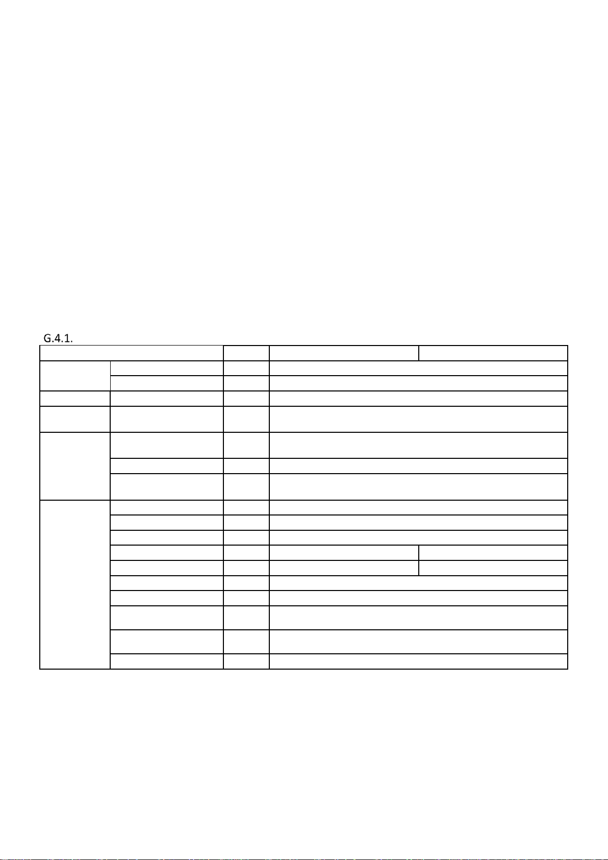
Page 59 of 71
SK2019 FSTD-SLIM-EC-FLEX-001_01
No16 stands for temperature sensor setting:
0=inner and external sensor are used. Inner sensor is to show room temperature. External sensor is used to show
water inlet temperature.
1=External sensor is connected, room temperature is based on external sensor. External sensor is not connected, room
temperature is based on inner sensor
No17 stands for unit configuration setting:
0=2-pipe
1=4-pipe
2=2pipe unit + floor heating
No18 stands for fan control setting:
0=DA, In cooling mode, fan is still on when setting temperature is reached.
1=DB, In heating mode, fan is off when setting temperature is reached.
No19 stands for DA1 setting:
0=EC fan control signal
1=Modulating valve control signal
I/O table
I/O
code
2-Pipe
4-Pipe
Power input
Power input
L
24 VAC or 24 VDC
GND
GND LED input
Wired wall pad input
TTL1
Wired wall pad
Analogue Input
External sensor(Ti1)
AI1
External sensor (Ti1)
The function is according to No16 setting.
Digital input
Occupancy contact
C1
Unit is ON. The switch is closed for 60S, the unit is OFF. It is turned ON again if
the switch is opened for 10s.
Input common wire
Com
Power input for outputs
L1
The power can be 230 VAC or 24 VAC. This is based on outputs signal
requirement.
Digital output
High speed
CN3
High speed- the power is based on L1 input.
Medium speed
CN4
Medium speed- the power is based on L1 input.
Low speed
CN5
Low speed- the power is based on L1 input.
Motorized valve1
MTV1
Chilled and hot valve for 2-pipe unit
Chilled valve
Motorized valve2
MTV2
No function
Hot valve
Auxiliary contact1
AUX1
Cooling mode signal relay (NO). Voltage free contact.
Auxiliary contact2
AUX2
Heating mode signal relay (NO). Voltage free contact.
EC fan or modulating valve
DA1
0~10VDC signal for EC fan or Modulating valve according to No.19 setting
MV modulating valve
DA2
0~10VDC signal for modulating valve
BUS ports
CN8
Modbus
Page 61

Page 60 of 71
SK2019 FSTD-SLIM-EC-FLEX-001_01
L1
GND
V1
A1
A2
Hi
Lo
DA1
Me
V2 S1
C1
L1
V1Hi
Lo
Me
V2
S1 C
A1 A2
GND DA1
24Vac
~
Legend:
L1: Hi,M,L, V1, V2 power supply;
Hi: High speed contact;
Med: Medium speed contact;
Lo: Low speed contact;
V1: Cooling valve contact;
V2: Heating valve contact;
S1: Remote on/off contact;
C1: COM
A1: Cooling status signal contact;
A2: Heating status signal contact;
A/B: RS485 port
AC/EC-S4 Thermostat Wiring scheme
A B
Thermostat control specification
Fan Coil Unit ON/OFF
There are 4 ways to turn the system on or off:
a) By the ON/OFF button wired wall pad.
b) By the programmable timer on wired wall pad.
c) By the occupancy contact.
d) By Modbus setting.
AUTO-RESTART
The system uses a non-volatile memory to save the present operation parameters when the system is turned off or in case of
system failure or cessation of power supply.
2-pipe thermostat control specification (Parameter 17=0)
1) Cooling mode
a) If Tr ≥ Ts + 1ºC (Parameter5 setting), then cool operation is activated. MTV1 and AUX1 are turned on. Indoor fan runs at
set speed.
b) If Tr < Ts, then cool operation is terminated and MTV1 and AUX2 are turned off. Indoor fan runs at set speed or stop
according to parameter18 setting.
c) The range of Ts is 16 - 30 ºC or fixed according to Parameter 4 setting.
d) Indoor fan speed can be adjusted for low, medium, high and auto.
Page 62

Page 61 of 71
SK2019 FSTD-SLIM-EC-FLEX-001_01
Low Temperature Protection of Indoor Coil (Parameter 16=0)
a) If Ti1 ≤ 2 ºC for 2 minutes, then MTV1 and AUX1 are turned off. If indoor fan is set for low speed, then it will run at medium
speed. If it is set at medium or high speed, then it will keep running at the same speed.
b) If Ti1 ≥ 5 ºC for 2 minutes, then MTV1 and AUX1 are turned on. Indoor fun runs at set speed.
2) Fan mode
a) Indoor fan runs at the set speed while heater, MTV1, MTV2, AUX1 and AUX2 are turned off.
b) Indoor fan speed can be adjusted for low, medium and high.
3) Heat mode
a) If Tr ≤ Ts- 1 ºC (Parameter 5 setting), then heat operation is activated and MTV1 and AUX2 are turned on. Indoor fan
runs at the set speed.
b) If Tr > Ts, heat operation is terminated and MTV1 and AUX2 are turned off. Indoor fan is turned off.
c) The range of Ts is 16 - 30 ºC or fixed according to Parameter 4 setting.
d) Indoor fan speed can be adjusted for low, medium, high and auto.
Anti-frozen protection in winter
If Tr<5ºC when unit is OFF, thermostat will be turned on to heating mode. When Tr>8ºC, thermostat will turned OFF.
4) SLEEP MODE
a) When sleep mode is turned ON:
Setting temperature point will increase by 0.5 ºC every 30 min in cooling mode, after 3 hours, the setting point will increase
by 3°C, the setting point is not increased.
Setting temperature point will decrease by 0.5 ºC every 30 min in heating mode, after 3 hours, the setting point will decrease
by 3°C, the setting point is not decreased.
b) When sleep mode is turned OFF, the setting point will be reset to pre-setting level.
5) Auto Fan Speed
COOL MODE
HEAT MODE
Fan speed cannot change until it has run at this
speed for more than 30 seconds.
Fan speed cannot change until it has run at this
speed for more than 30 seconds.
After 30 seconds the fan speed is modulated according to the difference between the room temperature and the set
temperature. The controller adjusts the motor signal input from 0 to 5VDC by PID calculation every 10 seconds. The air flow is
adjusted from 15% to100%
6) EC FAN CONTROL SIGNAL (Parameter 19=0)
Fan is set at high speed, DA1 output is according to Modbus address 310003 setting.
Fan is set at medium speed, DA1 output is according to Modbus address 310002 setting.
Fan is set at low speed, DA1 output is according to Modbus address 310001 setting.
Fan is set auto speed, DA1 is based on Tr, Ts PI calculation.
Minimum DA1 output is according to Modbus address 310000 setting.
Page 63

Page 62 of 71
SK2019 FSTD-SLIM-EC-FLEX-001_01
7) Modulating valve control signal (Parameter 19=1)
DA1 is based on Tr, Ts PI calculation to output 0~10 VDC.
Minimum DA1 output is according to Modbus address 310000 setting.
8) PRO1(C1) input
The unit is on. If C1 input is closed for 60s, the unit is turned OFF. If C1 input is opened for 10s, the unit will be turned ON
again.
4-pipe thermostat control specification (Parameter 17=1)
1) Cooling mode
a) If Tr ≥ Ts + 1ºC (Parameter5 setting), then cool operation is activated. MTV1 and AUX1 are turned on. Indoor fan runs at
set speed.
b) If Tr < Ts, then cool operation is terminated and MTV1 and AUX2 are turned off. Indoor fan runs at set speed or stop
according to parameter18 setting.
c) The range of Ts is 16 - 30 ºC or fixed according to Parameter 4 setting.
d) Indoor fan speed can be adjusted for low, medium, high and auto.
Low Temperature Protection of Indoor Coil (Parameter 16=0)
a) If Ti1 ≤ 2 ºC for 2 minutes, then MTV1 and AUX1 are turned off. If indoor fan is set for low speed, then it will run at medium
speed. If it is set at medium or high speed, then it will keep running at the same speed.
b) If Ti1 ≥ 5 ºC for 2 minutes, then MTV1 and AUX1 are turned on. Indoor fun runs at set speed.
2) Fan mode
a) Indoor fan runs at the set speed while heater, MTV1, MTV2, AUX1 and AUX2 are turned off.
b) Indoor fan speed can be adjusted for low, medium and high.
3) Heat mode
a) If Tr ≤ Ts- 1 ºC (Parameter 5 setting), then heat operation is activated and MTV2 and AUX2 are turned on. Indoor fan
runs at the set speed.
b) If Tr > Ts, heat operation is terminated and MTV2 and AUX2 are turned off. Indoor fan is turned off.
c) The range of Ts is 16 - 30 ºC or fixed according to Parameter 4 setting.
d) Indoor fan speed can be adjusted for low, medium, high and auto.
Anti-frozen in Winter
If Tr<5ºCwhen unit is OFF, thermostat will be turned on in heating mode. When Tr>8ºC, thermostat will turned OFF.
4) Sleep mode
When sleep mode is turned ON:
Setting temperature point will increase by 0.5 ºC every 30 min in cooling mode, after 3 hours, the setting point will increase
by 3°C, the setting point is not increased.
Setting temperature point will decrease by 0.5 ºC every 30 min in heating mode, after 3 hours, the setting point will decrease
by 3°C, the setting point is not decreased.
When sleep mode is turned OFF, the setting point will reset to pre-setting level.
Page 64

Page 63 of 71
SK2019 FSTD-SLIM-EC-FLEX-001_01
5) Auto Fan Speed
COOL MODE
HEAT MODE
Fan speed cannot change until it has run at this
speed for more than 30 seconds.
Fan speed cannot change until it has run at this
speed for more than 30 seconds.
After 30 seconds the fan speed is modulated according to the difference between the room temperature and the set
temperature. The controller adjusts the motor signal input from 0 to 5VDC by PID calculation every 10 seconds. The air flow is
adjusted from 15% to100%
6) EC fan control signal (Parameter 19=0)
Fan is set at high speed, DA1 output is according to Modbus address 310003 setting.
Fan is set at medium speed, DA1 output is according to Modbus address 310002 setting.
Fan is set at low speed, DA1 output is according to Modbus address 310001 setting.
Fan is set auto speed, DA1 is based on Tr, Ts PI calculation.
Minimum DA1 output is according to Modbus address 310000 setting.
7) Modulating valve control signal (Parameter 19=1)
DA1 is based on Tr, Ts PI calculation to output 0~10 VDC.
Minimum DA1 output is according to Modbus address 310000 setting.
8) PRO1(C1) input
While the unit is on, if C1 input is closed for 60s, the unit is turned OFF. If C1 input is opened for 10S, the unit will be turned
ON again.
Page 65

Page 64 of 71
SK2019 FSTD-SLIM-EC-FLEX-001_01
2-pipe +floor heating control specification (Parameter 17=2)
1) Cooling mode
a) If Tr ≥ Ts + 1ºC (Parameter5 setting), then cool operation is activated. MTV1 and AUX1 are turned on. Indoor fan runs at
set speed.
b) If Tr < Ts, then cool operation is terminated and MTV1 and AUX2 are turned off. Indoor fan runs at set speed or stop
according to parameter18 setting.
c) The range of Ts is 16 - 30 ºC or fixed according to Parameter 4 setting.
d) Indoor fan speed can be adjusted for low, medium, high and auto.
Low temperature protection of indoor coil (Parameter 16=0)
If Ti1 ≤ 2 ºC for 2 minutes, then MTV1 and AUX1 are turned off. If indoor fan is set for low speed, then it will run at medium
speed. If it is set at medium or high speed, then it will keep running at the same speed.
a) If Ti1 ≥ 5 ºC for 2 minutes, then MTV1 and AUX1 are turned on. Indoor fun runs at set speed.
2) Fan mode
a) Indoor fan runs at the set speed while heater, MTV1, MTV2, AUX1 and AUX2 are turned off.
b) Indoor fan speed can be adjusted for low, medium and high.
3) Heat mode
a) If Tr ≤ Ts - 1 ºC (Parameter 5 setting), then heat operation is activated and MTV2 and AUX2 are turned on. Indoor fan is
OFF.
b) If Tr > Ts, heat operation is terminated and MTV2 and AUX2 are turned off. Indoor fan is OFF.
c) The range of Ts is 16 - 30 ºC or fixed according to Parameter 4 setting.
d) Indoor fan is OFF.
Anti-frozen in Winter
If Tr<5ºC when unit is OFF, thermostat will be turned on in heating mode. When Tr>8ºC, thermostat will turned OFF.
4) Sleep mode
When sleep mode is turned ON:
Setting temperature point will increase by 0.5 ºC every 30 min in cooling mode, after 3 hours, the setting point will increase
by 3°C , the setting point is not increased.
Setting temperature point will decrease by 0.5 ºC every 30 min in heating mode, after 3 hours, the setting point will decrease
by 3°C , the setting point is not decreased.
When sleep mode is turned OFF, the setting point will be reset to pre-setting level.
5) Modulating valve control signal (Parameter 19=1)
DA1 is based on Tr, Ts PI calculation to output 0~10 VDC.
Minimum DA1 output is according to Modbus address 310000 setting.
6) PRO1 (C1) input
While the unit is on, if C1 input is closed for 60s, the unit is turned OFF. If C1 input is opened for 10S, the unit will be turned
ON again.
Page 66

Page 65 of 71
SK2019 FSTD-SLIM-EC-FLEX-001_01
MODBUS Communication Protocols for Thermostat
01 Read Coils:
02 Read Discrete Inputs:
Serial number
Specification
Protocol Specification
1
Media
RS485
2
Baud Rate
9600 BPS
3
Transmit Mode
RTU
4
Data Unit
Additional address + Function code + Data + CRC
5
Address
1-32
6
Function Code
1, 2, 3, 4, 6
7
DATA
0-255
8
CRC
CRC-16
9
Parity
Odd Parity
10
0 Address
Broadcast Address
Function Code
Outputs Register
Addresses
Protocol Specification
Data Define
01 1 Valve 1
“0” =OFF, ”1”=ON
01
5
Fan speed- High
“0”=OFF,”1”=ON
01
6
Fan speed- Med
“0”=OFF, ”1”=ON
01 7 Fan speed- low
“0”=OFF, ”1”=ON
01 8 Valve 2
“0”=OFF, ”1”=ON
01 9 Sleep mode
“0”=OFF, “1”=ON
Function Code
Discrete Inputs Register
Addresses
Protocol Specification
Data Define
02
3
Internal sensor
“0”=OK, ”1”=FAULT
02
4
External sensor
“0”=OK, ”1”=FAULT
Page 67

Page 66 of 71
SK2019 FSTD-SLIM-EC-FLEX-001_01
03 Read Holding Registers:
Function Code
Holding Register Addresses
Protocol
Specification
Data Define
03/06 3 State
“0”=OFF, ”01”=ON,
02=low temperature protection (R)
03/06 4 Mode
1=Cool, 2=Heat, 3=Ventilation
03/06
5
Set Room
Temperature
Temperature (16 - 30℃)
03/06
6
Fan Mode
00=High, 01=Med, 02=Low, 03=Auto
03 7 Model
01=DA, 02=DB, 11=FCV2
03/06
8
Frost Protection
Temperature
Temperature(8℃)
03/06
12
Enable Frost
Protection
“0”= Disable, ”01”= Enable
03/06
13
Key lock
“0”= Disable, ”01”= Enable
03/06
14
DA1 setting
0=EC fan control signal
1=Modulating valve control signal
03/06
15
Unit type
0= Fan coil thermostat
1=Floor heating thermostat
04 Read Input Registers:
Remarks:
The range of temperature: (0~80℃)
E.G: Temperature = 25.5°C, the date(255) = 00H FFH
Temperature = 5.0°C, the date(50) = 00H 32H
Function Code
Input Register Addresses
Protocol
Specification
Data Define
04
1
Room temperature
Temperature (0~+80℃)
04
2
DA1 output
0~10 VDC
Page 68

Page 67 of 71
SK2019 FSTD-SLIM-EC-FLEX-001_01
Sensor Resistance R-T Conversion Table
Resistance : R (25°C) = 10KΩ ± 1%
Beta Constant : B (25/85) = 3977 ± 1%
T
Rmin
Rnom
Rmax
T
Rmin
Rnom
Rmax
(°C)
(KΩ)
(KΩ)
(KΩ)
(°C)
(KΩ)
(KΩ)
(KΩ)
-30
174
182.7
191.8
4
26.11
26.9
27.71
-29
163.4
171.5
179.9
5
24.85
25.59
26.34
-28
153.6
161.1
168.9
6
23.65
24.35
25.05
-27
144.4
151.3
158.5
7
22.52
23.17
23.83
-26
135.8
142.2
148.9
8
21.45
22.06
22.68
-25
127.8
133.8
140
9
20.44
21.01
21.59
-24
120.3
125.8
131.6
10
19.48
20.02
20.55
-23
113.3
118.4
123.8
11
18.58
19.7
19.58
-22
106.7
111.5
116.5
12
17.71
18.18
18.65
-21
100.6
105.1
109.7
13
16.9
17.33
17.77
-20
94.9
99.03
103.3
14
16.12
16.53
16.94
-19
89.51
93.39
97.41
15
15.39
15.77
16.16
-18
84.5
88.11
91.85
16
14.69
15.05
15.41
-17
79.8
83.17
86.64
17
14.03
14.37
14.7
-16
75.39
78.53
81.76
18
13.41
13.72
14.03
-15
71.26
74.18
77.19
19
12.81
13.1
13.4
-14
67.37
70.1
72.9
20
12.24
12.52
12.79
-13
63.73
66.26
68.88
21
11.7
11.96
12.22
-12
60.3
62.67
65.1
22
11.19
11.43
11.67
-11
57.08
59.28
61.55
23
10.71
10.93
11.15
-10
54.05
56.1
58.22
24
10.24
10.45
10.66
-9
51.19
53.12
55.08
25
9.8
10
10.2
-8
48.51
50.3
52.14
26
9.374
9.57
9.765
-7
45.98
47.66
49.37
27
8.969
9.16
9.351
-6
43.61
45.17
46.77
28
8.584
8.77
8.957
-5
41.36
42.82
44.31
29
8.218
8.4
8.582
-4
39.25
40.61
42
30
7.869
8.047
8.225
-3
37.26
38.53
39.83
31
7.537
7.71
7.885
-2
35.38
36.56
37.78
32
7.221
7.39
7.56
-1
33.6
34.71
35.85
33
6.92
7.085
7.251
0
31.93
32.97
3402
34
6.633
6.794
6.956
1
30.35
31.32
32.3
35
6.36
6.517
6.675
2
28.85
29.76
30.68
36
6.099
6.252
6.407
3
27.44
28.29
29.15
37
5.85
6
6.151
Page 69

Page 68 of 71
SK2019 FSTD-SLIM-EC-FLEX-001_01
Resistance : R (25°C) = 10KΩ ± 1%
Beta Constant : B (25/85) = 3977 ± 1%
T
Rmin
Rnom
Rmax
T
Rmin
Rnom
Rmax
(°C)
(KΩ)
(KΩ)
(KΩ)
(°C)
(KΩ)
(KΩ)
(KΩ)
38
5.614
5.759
5.907
75
1.417
1.474
1.532
39
5.387
5.53
5.673
76
1.37
1.426
1.482
40
5.172
5.31
5.451
77
1.326
1.379
1.434
41
4.966
5.101
5.238
78
1.282
1.335
1.389
42
4.769
4.901
5.034
79
1.241
1.292
1.344
43
4.582
4.71
4.84
80
1.201
1.25
1.302
44
4.402
4.527
4.654
81
1.162
1.211
1.261
45
4.231
4.353
4.477
82
1.125
1.172
1.221
46
4.067
4.186
4.307
83
1.089
1.135
1.183
47
3.911
4.027
4.144
84
1.055
1.1
1.146
48
3.761
3.874
3.989
85
1.021
1.065
1.111
49
3.618
3.728
3.84
86
0.9891
1.032
1.077
50
3.481
3.588
3.697
87
0.9582
1
1.044
51
3.35
3.454
3.561
88
0.9284
0.9697
1.012
52
3.225
3.326
3.43
89
0.8998
0.9401
0.9818
53
3.105
3.204
3.305
90
0.8721
0.9115
0.9522
54
2.99
3.086
3.185
91
0.8455
0.8839
0.9237
55
2.88
2.974
3.07
92
0.8198
0.8573
0.8961
56
2.774
2.866
2.959
93
0.795
0.8316
0.8696
57
2.673
2.762
2.854
94
0.7711
0.8069
0.8439
58
2.576
2.663
2.752
95
0.748
0.783
0.8192
59
2.483
2.568
2.655
96
0.7258
0.7599
0.7953
60
2.394
2.477
2.562
97
0.7043
0.7376
0.7722
61
2.309
2.39
2.472
98
0.6836
0.7161
0.7499
62
2.227
2.306
2.386
99
0.6635
0.6953
0.7283
63
2.149
2.225
2.304
100
0.6442
0.6752
0.7075
64
2.073
2.148
2.224
101
0.6255
0.6558
0.6874
65
2.001
2.074
2.148
102
0.6075
0.6371
0.6679
66
1.931
2.002
2.075
103
0.59
0.619
0.6491
67
1.865
1.934
2.005
104
0.5732
0.6015
0.631
68
1.801
1.868
1.937
105
0.5569
0.5846
0.6134
69
1.739
1.805
1.872
70
1.68
1.744
1.81
71
1.623
1.686
1.75
72
1.569
1.63
1.692
73
1.516
1.576
1.637
74
1.466
1.524
1.583
Page 70
Page 69 of 71
SK2019 FSTD-SLIM-EC-FLEX-001_01
Troubleshooting
Symptoms
Cause
Remedy
The fan coil does not
start up
No voltage
Mains switch in the “OFF” position
Faulty room control
Faulty fan
- Check for presence of voltage
- Check fuse on board
- Place in the “ON” position
- Check the room control
- Check fan motor
Filter clogged
Air flow obstructed
Room control regulation
Incorrect water temperature
Air present
Insufficient output
- Clean the filter
- Remove obstacles
- Check the room air sensor
- Check the water source
- Check the air vent
Contact between metal parts
Loose screws
Noise and vibrations
- Check for loosening parts
- Tighten screws
Page 71

Page 70 of 71
SK2019 FSTD-SLIM-EC-FLEX-001_01
Accessories Descriptions
Electrical Heater
Electric Heater module is supplied for winter heating as an alternative to the auxiliary hot water coil.
Electric Heater is installed in the same way and same position as the Auxiliary 1 row heating coil for 4-pipe system.
Note: Airflow should not drop below the values for minimum speed.
Page 72

Page 71 of 71
SK2019 FSTD-SLIM-EC-FLEX-001_01
Auxiliary External Drain Pan
DPANPS-UNSL-RH is a painted steel drain pan for suspended ceiling installation or built-in horizontal installation with rightsided coil connections.
DPANPS-UNSL-LH is a painted steel drain pan for suspended ceiling installation or built-in horizontal installation with left-sided
coil connections.
DPANPS-UNSL-RHLH is a painted steel drain pan for floor standing installation, fixed wall installation and built-in vertical
installations. Suitable for left-side and right-side unit coil connections.
DPANPS-UNSL-RHLH
DPANPS-UNSL-RH
DPANPS-UNSL-LH
Supporting Feet
ABSFT UNISL EXP1 Metal supporting feet for floor standing applications.
Page 73

Eurofred S.A.
Marqués de Sentmenat 97
08029 Barcelona
www.eurofred.es
 Loading...