

DAITEM SH640AX Installation Instruction
2
1. Introduction
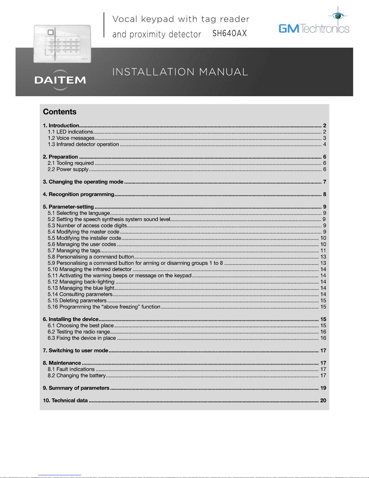
Infrared detector
Two-colour LED
Buttons
for access codes
and programming
LED and pictogram indicating tag reading zone.
Blue light
If the level of lighting is low, a key is pressed or the detector triggered (see Infrared detector operation), the buttons and
keypad are back-lit for 10 s.
The back-lighting period is repeated for 10 s when the last key is pressed.
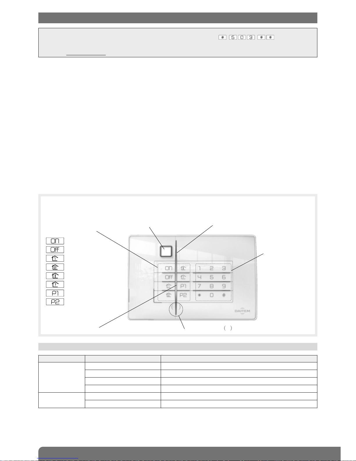
LED LED status Meaning
Red steady key pressed correctly
1 flash every 5 s keypad in test mode
2 flashes every 10 s keypad in installation mode
3 quick flashes handling or programming error, access code invalid
Green steady for 2 s correct programming
steady for 10 s access code valid (the 10 s period is repeated after each command)
1.1 LED indications
The vocal keypad with tag reader and proximity detector can be used to operate an intrusion protection system from outside
or inside the home.
The keypad commands can be accessed:
• using the master code,
• using the 8 user codes,
• using a tag (24 tags max).
Each command is confirmed with a voice message and a visual signal (LED) issued by the keypad. The keypad indicates:
• the system status,
• the status of alarms,
• the status of exit points,
• faults.
The speech synthesis system also helps with keypad use and programming.
The vocal keypad also has an infrared detector able to detect an approaching person.
The keypad is protected against:
• opening,
• removal,
• attempts to discover the access code.
8 command keys
can be personalised
Arm
Disarm
Partial 1
Partial 2
Arm Presence
System status query
Not allocated
Not allocated
IMPORTANT
• Some functions are only available with control panel versions 2.0.0 or later (enter on the control
panel keypad to check the version).
• Operational differences in relation to former ranges are described in the compatibility booklet available in the Daitem Installers
section at www.daitem.co.uk.
3
1.2 Voice messages
IMPORTANT: only the commands sent from the vocal keypad result in the following messages. Orders issued by another remote
control unit do not lead to a keypad response.
Following a command Voice message
Disarm “bip, off”
Arm “bip, armed”
Partially arm 1 “bip, armed partial one”
Partially arm 2 “bip, armed partial two”
Disarm group X (X = 1 to 8) “bip, off group X”
Arm group X (X = 1 to 8) “bip, armed, group X”
Arm presence “bip, armed presence”
System status query “bip, system status, armed”
“bip, system status, armed partial one two”
“bip, system status, off”
“bip, system status, armed group X”
“bip, system status armed presence”
Change to test mode “bip, test mode”
Change to installation mode “bip, installation mode”
Change to user mode “bip, user mode”
The keypad issues the following voice messages:
Following a command Voice message
Disarm... “bip, off ..., alarm System”
It also indicates:
• possible alarms following a Disarm command
Following a command Voice message
Disarm... “bip, off ..., fault system”
Arm... “bip, armed ..., fault system”
“bip, armed ..., exit opened”
System status query “bip, system_ status..., fault system”
“bip, system status..., exit opened”
“bip, system status..., exit inhibited”
• faults and the status of exit points following a Disarm, Arm or system status query command
Example:
The system is in Armed Partial Two mode and the keypad has a battery fault.
When a “System status query” order is sent from the vocal keypad, the keypad and control panel issue the following messages:
The keypad also indicates information feedback as shown below:
Command sent to: LED status and colour Meaning
An alarm control panel lights up steady GREEN for 1.5 s Total or group DISARMING
flashes GREEN 3 times Total or group DISARMING with alarm memory
lights up steady RED for 1.5 s Total, partial or group ARMING
flashes RED 3 times ARMING blocked (1)
A command receiver
or remote-controlled socket
lights up steady GREEN for 1.5 s Transmission of a home control command
(light, relay, etc.)
(1) Arming blocked means that the intrusion system has been unable to arm owing to a system fault.
The user must check the control panel for more information.
“Bip, System_status, Armed Partial
Two, bip, on 12/03 at 12 PM, Fault
Voltage Remote_control_unit 1”
“Bip, System_status,
Armed Partial Two, bip,
Fault System”

4
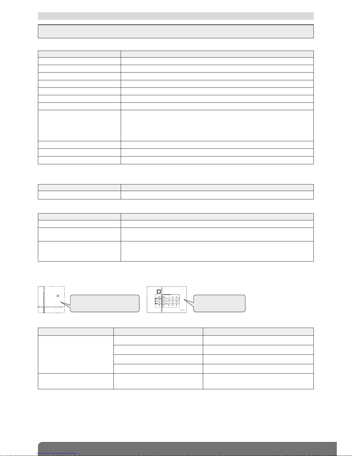
Like a conventional infrared motion detector, the keypad
detector is allocated to an intrusion group and its alarm level
can be set.
Different types of triggering are possible:
• immediate,
• delayed,
• combined.
• The distant detection zone
Top view
Side view
• The close detection zone
Top view
Side view
2 m
2 m
0,8 m
1.6 m
1.3 m
1.3 m
1.2 m
0.5 m
0.5 m
0.3 m
0.2 m
1.8 m
0.4 m
1.3 Infrared detector operation
IMPORTANT: if the infrared detector is directed at the sun it is likely to be triggered for no reason.
IMPORTANT: it is not advisable to programme the infrared
detector for immediate triggering.
Time-delayed triggering
In the event of intrusion, the alerts and deterrents are
triggered at the end of the entry time delay.
keypad
door
window
The vocal keypad has an infrared detector enabling it to detect an approaching person.
It has 2 distinct detection zones:
For an efficient close
detection, infrared
detector must not be
installed at height upper
than 1.3 m.
5
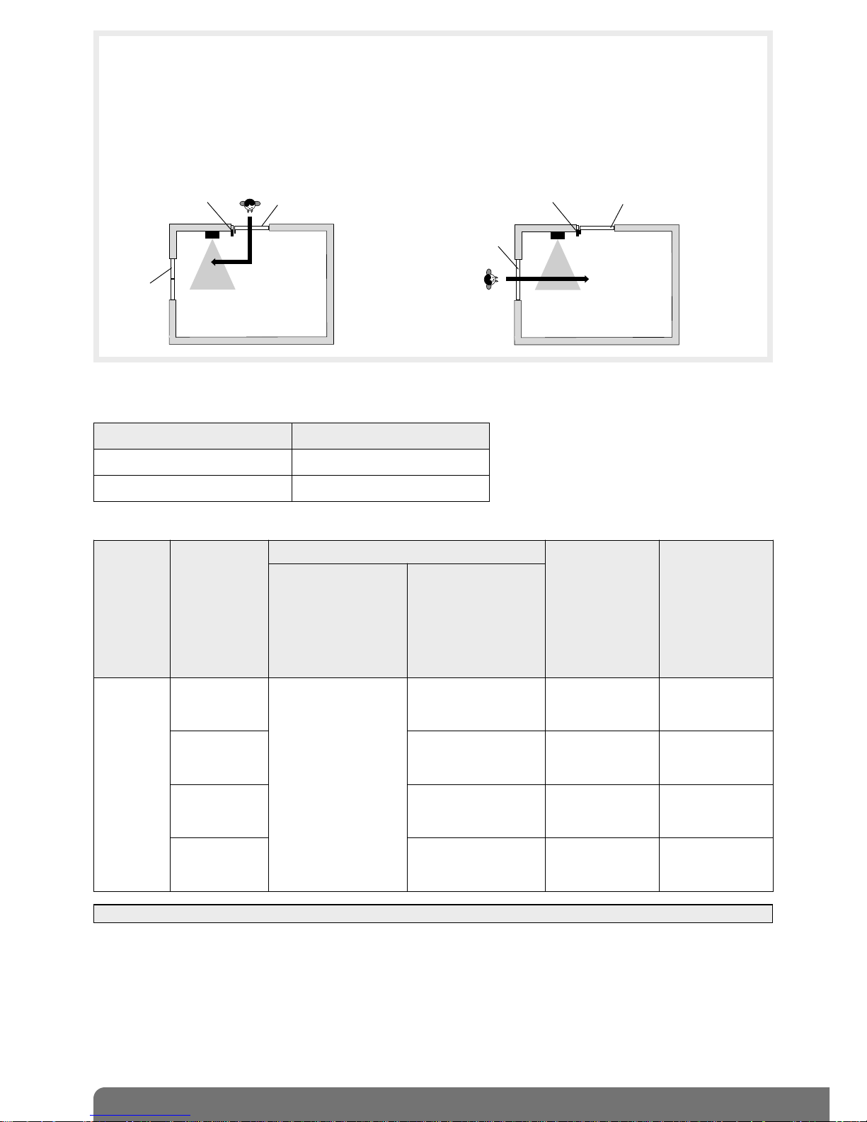
Depending on the alarm system status, the keypad will operate as follows:
1. Alarm system status: Disarmed
Detection Keypad response
Distant No response
Close Back-lighting for 10 s
(1) IMPORTANT: the message or warning beeps are issued if parameter 23 has been enabled (factory disabled).
2. Alarm system status: Totally Armed or Group to which the keypad infrared detector has been allocated Armed:
Example:
• The user enters his home:
The door/window detector detects his presence and
the keypad motion detector observes a time delay
allowing the user to reach the keypad and stop the
system.
Combined triggering
A combined detector will trigger immediately if it is the first detector to be set off. It will observe a time delay before
triggering if another time-delayed detector detects something first.
• In the event of intrusion via a window:
The door/window detector is not set off whereas the
keypad motion detector is immediately triggered
along with the other alerts and deterrents.
time-delayed
door/window
detector
keypad
keypad
door
window
time-delayed
door/window
detector
door
window
Detection
Infrared
detector
alarm level
Keypad response
Control panel
response
Siren response
Time-delayed
triggering of infrared
detector
(detector programmed
for time delay or
combined operation
and triggered 2nd)
Immediate triggering
of infrared detector
(detector programmed
for combined
operation
and triggered 1st)
Distant
or
close
Intrusion
• back-lighting
for 10 s
• warning message
“bip, bip, bip,
protection active” (1)
no response
loud sounding
for 90 s
loud sounding
for 90 s + strobe
flashing for 15 min
Prealarm
• back-lighting for 10 s
• series of 10 beeps (1)
loud sounding
for 15 s
loud sounding
for 15 s + strobe
flashing for 15 s
Deterrence
• back-lighting for 10 s
• series of 5 beeps (1)
series of beeps
for 5 s
series of beeps
for 5 s + strobe
flashing for 5 s
Warning
• back-lighting for 10 s
• series of 3 beeps (1)
series of beeps
for 2 s
series of beeps
for 2 s + strobe
flashing for 5 s
6
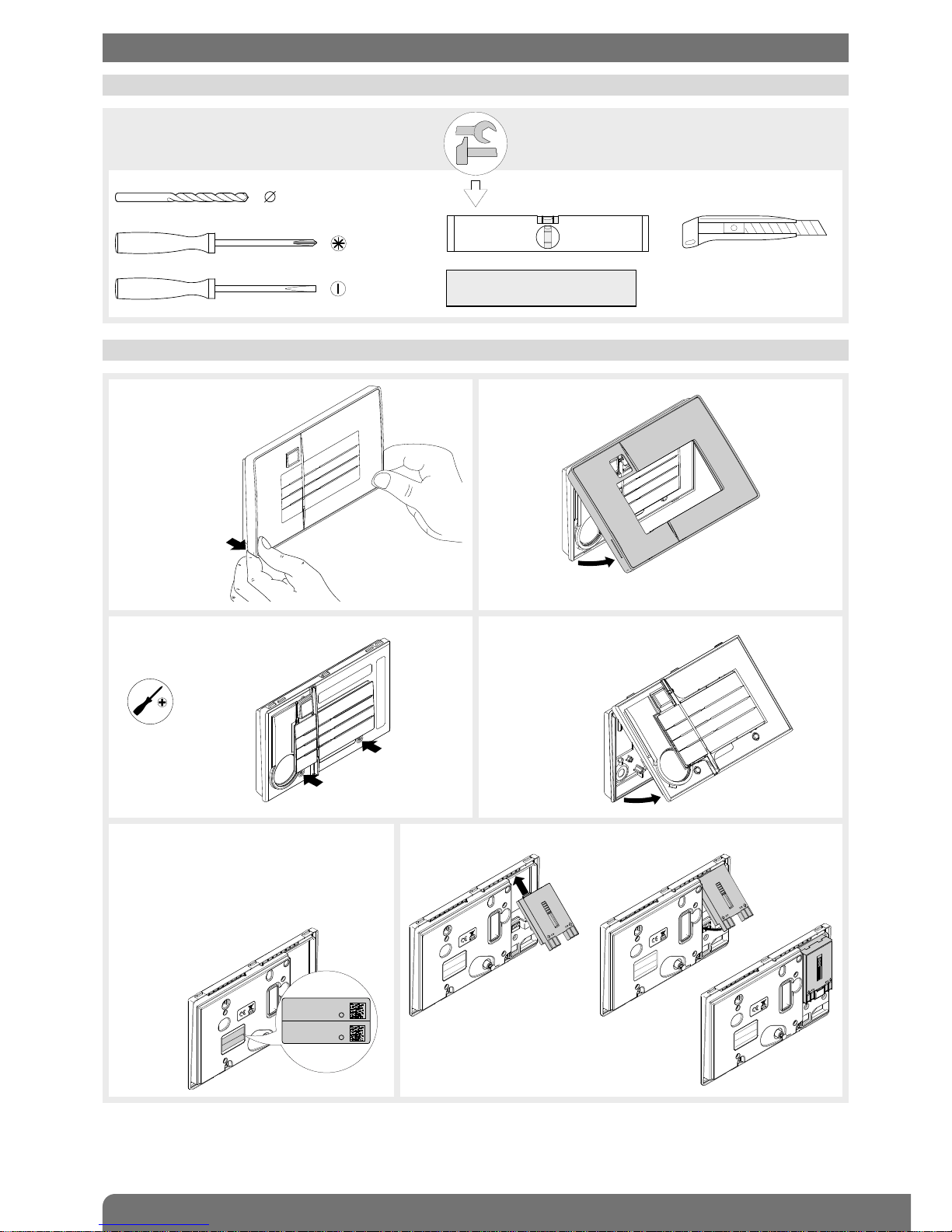
2.1 Tooling required
6 mm
2.5 mm
PH.1
2. Preparation
IMPORTANT: the fixing screws
and plugs are not provided.
1. Unclip the front panel
from the bottom.
2. Remove the front panel.
3. Loosen the 2 screws. 4. Remove the electronic part
from the base.
5. Remove the pre-cut part of the sticker and
stick it to the guarantee certificate inside
the user manual supplied with the control
panel. If you are adding to an existing
system, use the guarantee certificate
supplied with this product.
6. Connect the lithium power pack to its support.
Philips PH.1
Coller sur certif
SH640AX
A1235A04823
SH640AX
A1235A04823
2.2 Power supply
 Loading...