

DAITEM SH602AX, SJ604AX, SJ608AX Installation Manual

Contents
1. Introduction.................................... ................................. 1
2. Preparation..................................... ................................. 2
3. Recognition programming with a TwinBand
®
alarm control panel................................ ........................ 3
4. Parameter-setting (TwinBand®radio) .......................... 3
4.1 Setting a command number ....................... ............... 3
4.2 Setting a key to Arm or Disarm groups 1 to 8 ... ....... 4
5. Radio link between the remote control keyfob
and an Optwin®wireless product................................. 5
5.1 Creating and deleting the radio link
between the remote control keyfob
and an Optwin®wireless product............................... 5
5.2 Deleting the radio links of a key
on the remote control keyfob....................... .............. 5
6. Locking the remote control keyfob via a code.... ...... 6
6.1 Procedure for locking or unlocking the keyfob .. ....... 6
6.2 Personalising the locking code................. ................. 6
7. Three-colour LED operation...................... ................... 6
7.1 Information feedback........................... ....................... 6
7.2 Confirmation of receipt......................... ...................... 7
7.3 Protected or locked keys ....................... .................... 7
7.4 Remote control battery fault ................... ................... 7
8. Maintenance ..................................... .............................. 7
8.1 Changing the battery........................... ....................... 7
8.2 Returning to the factory configuration.......... ............. 8
9. Technical data.................................. ............................... 8
Recommendations
The user must not attempt to access the device’s in ternal parts, except areas described in this manual . If the user does
access these parts, the product guarantee will be c onsidered null and void and DAITEM shall not be hel d responsible for any
problems. Touching the device’s internal parts and/ or electronic components can damage the product. Furthermore, the
device is designed in such a way that these parts a nd components do not need to be accessed for operation or
maintenance purposes.
The remote control devices SJ604AX and SJ608AX comb ine two radio protocols (TwinBand®and Optwin®) allowing them to
control several product ranges.
The remote control device SH602AX operates only on the TwinBand®radio protocol, it does not operate on the Optwin
®
radio protocol.
• The keyfob can be used to control:
- the intrusion protection function of the alarm sy stem hence ensuring the protection of individuals (TwinBand®radio),
- latch/gate access points using the wireless doorp hone system (Optwin®), except for the SH602AX,
- comfort applications with external receivers or t he remote-controlled socket (TwinBand®and Optwin®.)
The keys can be personalised to adapt the commands to the user’s habits.
• Factory configuration of remote control keyfobs
The SJ608AX keyfob has a cursor (top and bottom pos ition) so that commands on each key can be doubled hence
providing up to 8 functions.
The commands allocated to keys are identical whatev er the position of the cursor (top or bottom).
1. Introduction
IMPORTANT
• Some functions are only available with control pa nel versions 2.0.0 or later (enter on the control
panel keypad to check the version).
• Operational differences in relation to former ran ges are described in the compatibility booklet avai lable in the Daitem Installers
section at www.daitem.co.uk .
INSTALLATION MANUAL
SH602AX: 2 function remote keyfob with information feedback
SJ604AX: bi-protocol 4 function remote keyfob
with information feedback
SJ608AX: 8 function 4 key remote keyfob
with information feedback
SJ608AX
SJ604AXSH602AX
2
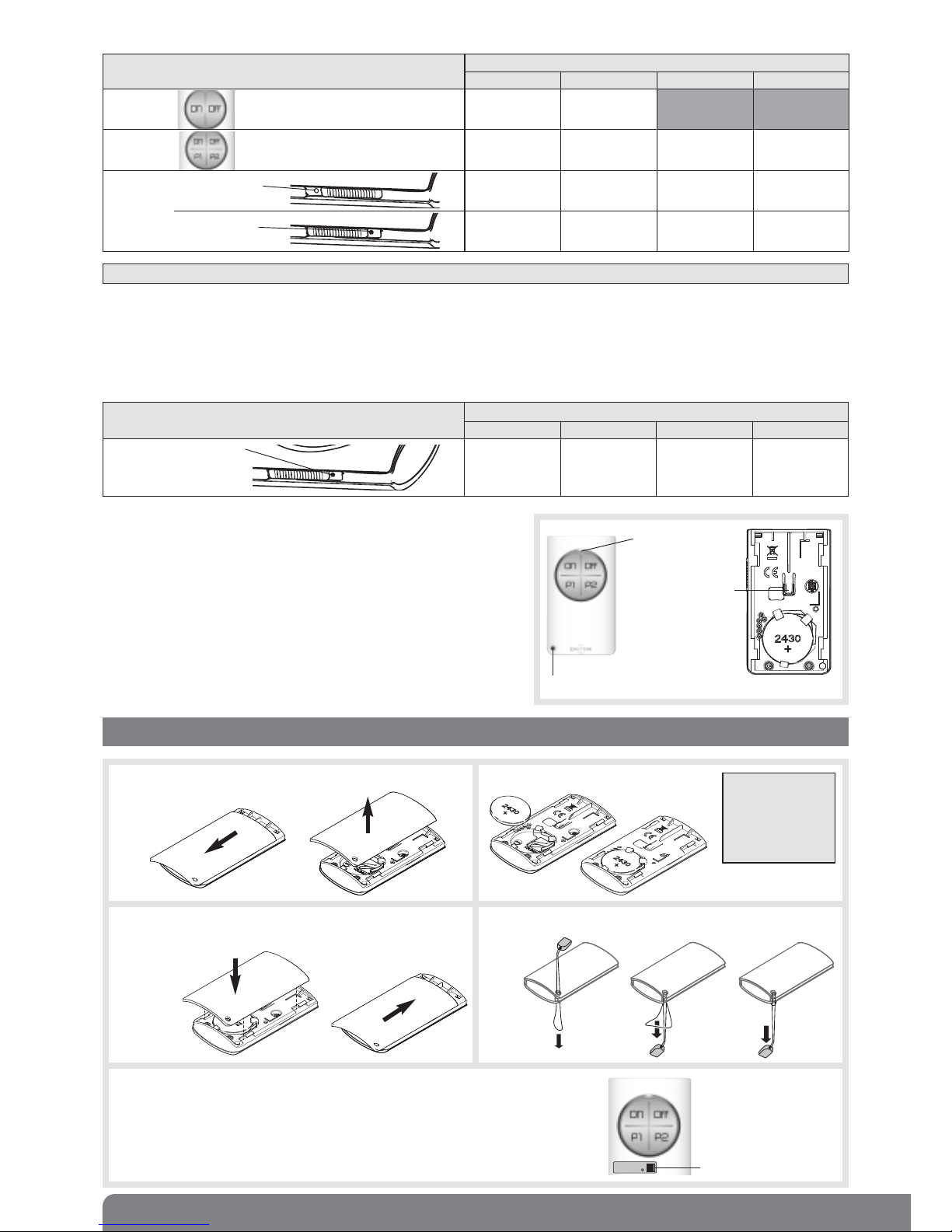
IMPORTANT: when the cursor is in the middle position, the keys are in protected mode and cannot issue radio commands.
• The keyfob has a three-colour LED on its front face indicating:
- radio transmission when a key is pressed,
- information feedback from the system being controlled or, failing
this, confirmation of receipt,
- the battery status.
This three-colour LED can also be used for different parameter
settings.
• The keyfob has a pushbutton for:
- returning to the keyfob’s factory configuration,
- creating or deleting a radio link between each key and Optwin
®
wireless devices (external receiver and doorphone).
Three-colour
LED
Pushbutton for
return to factory
configuration and
creation of radio
link (Optwin®)
Hole for cord
2. Preparation
2. Position the battery (supplied).1. To connect the battery, slide the rear base down
by about 5 mm and then pull it up.
IMPORTANT:
make sure you
position the
battery the right
way round with
the “+” facing up.
4. Insert the cord.3. Put the rear base back by sliding it upwards until it locks
into position.
5. Guarantee sticker
Remove the pre-cut part of the sticker and stick it on to the guarantee
certificate inside the user manual supplied with the control panel. If you
are adding to an existing system, use the guarantee certificate supplied
with this product.
Guarantee sticker
SJ604AX
A1042A047879
Coller sur certif
Keyfob reference
Factory configuration of keys
ON OFF P1 P2
SH602AX
Arm Disarm
SJ604AX
Arm Disarm Partially arm 1 Alert
SJ608AX
Cursor
in top
position
Arm Disarm Partially arm 1 Alert
Cursor
in bottom
position
Arm Disarm Partially arm 1 Alert
White
marker
Blue
marker
The keys are configured to issue the following commands:
• Specific feature of the SJ608AX keyfob
When a command n° has been configured (TwinBand®) and a radio link created (Optwin®) for one of the keys, then the
cursor is in the bottom position while the other keys are automatically configured to be disabled (command n° 44 for
TwinBand®radio).
Example: the cursor is in the bottom position and the P1 key parameter is set for the “Silent alarm” command. The other
three keys are disabled.
SJ608AX keyfob
Factory configuration of keys
ON OFF P1 P2
Cursor
in bottom
position
Key disabled Key disabled Silent alarm Key disabled
Blue
marker
3
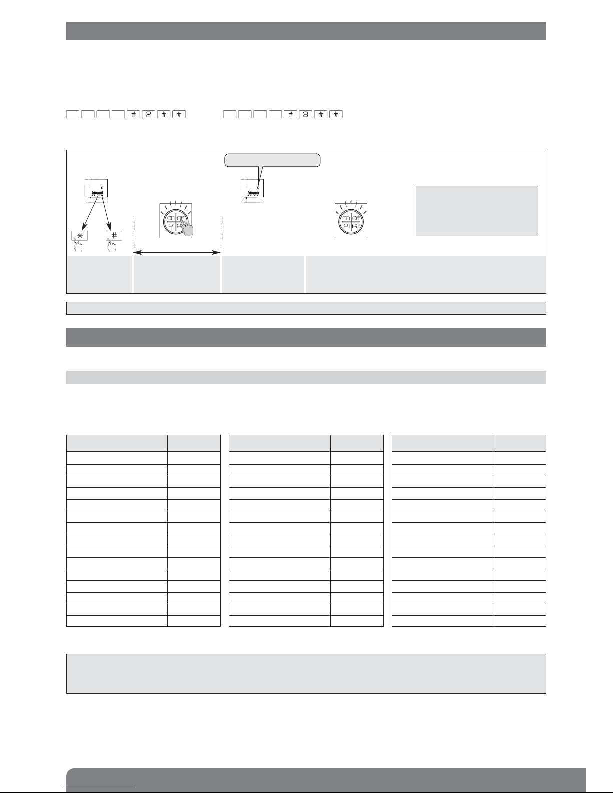
This step enables radio recognition between devices:
• the keyfob is recognised by the control panel,
• the control panel is recognised by the keyfob (for managing control panel information feedback on the keyfob).
To perform recognition programming, place the cursor in the top position for keyfob SJ608AX.
The control panel must be in installation mode. If it is not, enter:
then
3. Recognition programming with a TwinBand®alarm control panel
The keyfob’s parameters can be set in order to personalise commands in relation to the user’s needs.
4. Parameter-setting (TwinBand®radio)
IMPORTANT: the keyfob can recognise two different alarm control panels and manage information feedback from both.
master code (factory: 0000) installer code (factory: 1111)
Perform the following recognition programming sequence:
Press *then # on
the control panel
keypad.
Press and hold “Off”
(orange LED flashes)
until the control panel
responds
10 s max.
then
“Bip, remote control unit X”
The control panel issues
a voice message to
confirm keyfob
recognition
The keyfob’s LED lights up
green for 1.5 s to confirm
control panel recognition
IMPORTANT: deleting control
panel recognition on a keyfob
can only be done once the
keyfob has been put back into
its factory configuration.
4.1 Setting a command number
1. Choose the keyfob key to be personalised (ON, OFF, P1 or P2)
2. Choose a command n° (2 or 3 digits) from the table below depending on the command to be set.
3. Choose a top or bottom cursor position (only for SJ608AX).
IMPORTANT
• To use the “Alert” or “Silent alarm” command, press and hold the key for 2 seconds in order to validate radio transmission.
• A key cannot be set with a TwinBand®command n° if an Optwin®radio link has already been allocated (unless the Optwin
®
radio link is deleted).
)
)
))
)
)
)
))
)
Command description Command n°
OFF
(coded access compulsory)
21
Panic Alarm 22
Armed 23
Silent alarm 24
Armed, Partial 1 25
Armed, Partial 2 27
Fire alarm 32
Armed, Presence mode
(stay)
33
Silent command 36
Stop indications* 37
Door Bell Chime 38
Audible signal Chime 42
No command 44
Pulse light 50
Light OFF 52
Command description Command n°
Light ON 54
Light toggle switch 56
Light timer 58
Pulse relay 1 60
OFF relay 1 62
Armed relay 1 64
Toggle switch relay 1 66
Timer relay 1 68
Pulse relay 2 70
OFF relay 2 72
Armed relay 2 74
Toggle switch relay 2 76
Timer relay 2 78
Pulse relay 3 80
OFF relay 3 82
Command description Command n°
Armed relay 3 84
Toggle switch relay 3 86
Timer relay 3 88
Pulse relay 4 90
OFF relay 4 92
Armed relay 4 94
Toggle switch relay 4 96
Timer relay 4 98
Off relay control panel 1 112
On relay control panel 1 114
Off relay control panel 2 122
On relay control panel 2 124
System status 129
* Used to stop indications concerning a technical alarm, an alert or a tamper alarm without changing the system status.
Important: telephone transmissions are not interrupted.
 Loading...