

DAITEM SH601AU Installation Manual

2
Contents
Foreword................................................................................................................................................................................. 3
1. Introduction ........................................................................................................................................................................ 4
2. Operation............................................................................................................................................................................ 5
3. Preparation......................................................................................................................................................................... 6
3.1 Guarantee sticker to be returned ................................................................................................................................. 6
3.2 Product label to be kept................................................................................................................................................ 6
3.3. Activating the pendant ................................................................................................................................................. 6
4. Recognition programming ............................................................................................................................................... 7
4.1 Programming for use with the control panel................................................................................................................ 7
4.2 Programming for use with the dialler............................................................................................................................ 8
5. Main configuration operations......................................................................................................................................... 9
6. Assembly .......................................................................................................................................................................... 12
6.1 Assembling the quick-fastener and neck cord .......................................................................................................... 12
6.2 Assembling the clip holder.......................................................................................................................................... 13
7. Testing operation and radio coverage in test mode................................................................................................... 14
8. Performing a real test...................................................................................................................................................... 16
9. Advanced programming................................................................................................................................................. 17
9.1 “Comfort” type application ......................................................................................................................................... 17
9.2 Programming a pendant relayed to a control panel................................................................................................... 18
10. Battery status indication............................................................................................................................................... 19
11. Technical data ................................................................................................................................................................ 19

3
Foreword
We would like to thank you for buying an alarm pendant. To install the pendant in the best conditions, we advise
you to do the following:
1. read the precautions to be taken (below) as well as the “Introduction” and “Operation” chapters,
2. follow the chronological order of the manual, which describes the different operations to be performed step by
step.
Precautions to be taken:
• The pendant has been designed with a non-dismountable enclosure to guarantee that it is watertight. The batteries cannot be
replaced. Change the pendant at the end of its battery life.
• In its factory configuration, the pendant’s battery life is 10 years (based on 1 activation per day). Depending on its use and
possible reprogramming, the pendant’s battery life may be reduced to roughly 5 years (based on 5 activations per day).
• In normal conditions of use, the sliding part of the pendant should be kept closed to prevent premature battery wear.
• If the user has a pacemaker, s/he must check with his/her doctor whether the device used is compatible with the pendant.
The pendant’s radio characteristics are given in the chapter entitled “Technical data” at the end of this manual.
• If the pendant’s batteries are not used for long periods of time, this may stop the pendant working. To prevent this from happening, it is
strongly advisable to perform a weekly battery test, as described in the chapter entitled “Battery status indication”. The user can also test
the status of the batteries at any time to check that the pendant is working properly.
• The pendant has an average radio range with respect to the control panel (or dialler) of 200 m in free field conditions. This means that it will
not work outside of this range given that the control panel (or dialler) will not be able to receive the messages transmitted by the pendant.
Likewise, the control panel (or dialler) will not transmit alarms to the pendant user if the user is located outside of this range.
Furthermore, owing to the composition of certain types of construction materials (some of which prevent or distort the propagation of radio
waves; see control panel manual), and depending on how the pendant is activated and worn (e.g. close to the body), the radio range can be
reduced. Taking into account these requirements, and in order to guarantee the best operating conditions for the user, it is essential to test
the pendant’s radio coverage as soon as it is installed. This test is described in the chapter entitled “Testing operation and radio
coverage in test mode”).
• Alarms transmitted by the pendant are sent to the control panel (or dialler) installed in the user’s home. They are taken into account
according to the configuration chosen when the pendant is installed. The pendant is not a medical tele-assistance device. It only enables a
certain number of alarms defined in this manual to be triggered. However, whatever its configuration, it cannot guarantee that the user
will receive personal or emergency assistance. When the pendant is connected to a remotely monitored alarm system, the alarms
transmitted to the remote monitoring service will be processed according to the provisions outlined in the remote monitoring contract.
Unless the emergency calls issued by the pendant are transmitted to a remote monitoring centre fitted with a medical unit, the alarms issued
will not be treated as medical emergencies. It is therefore up to pendant users wishing to be connected to a remote monitoring company
to ensure the company offers this type of service, and notably to check whether it provides medical assistance.
4
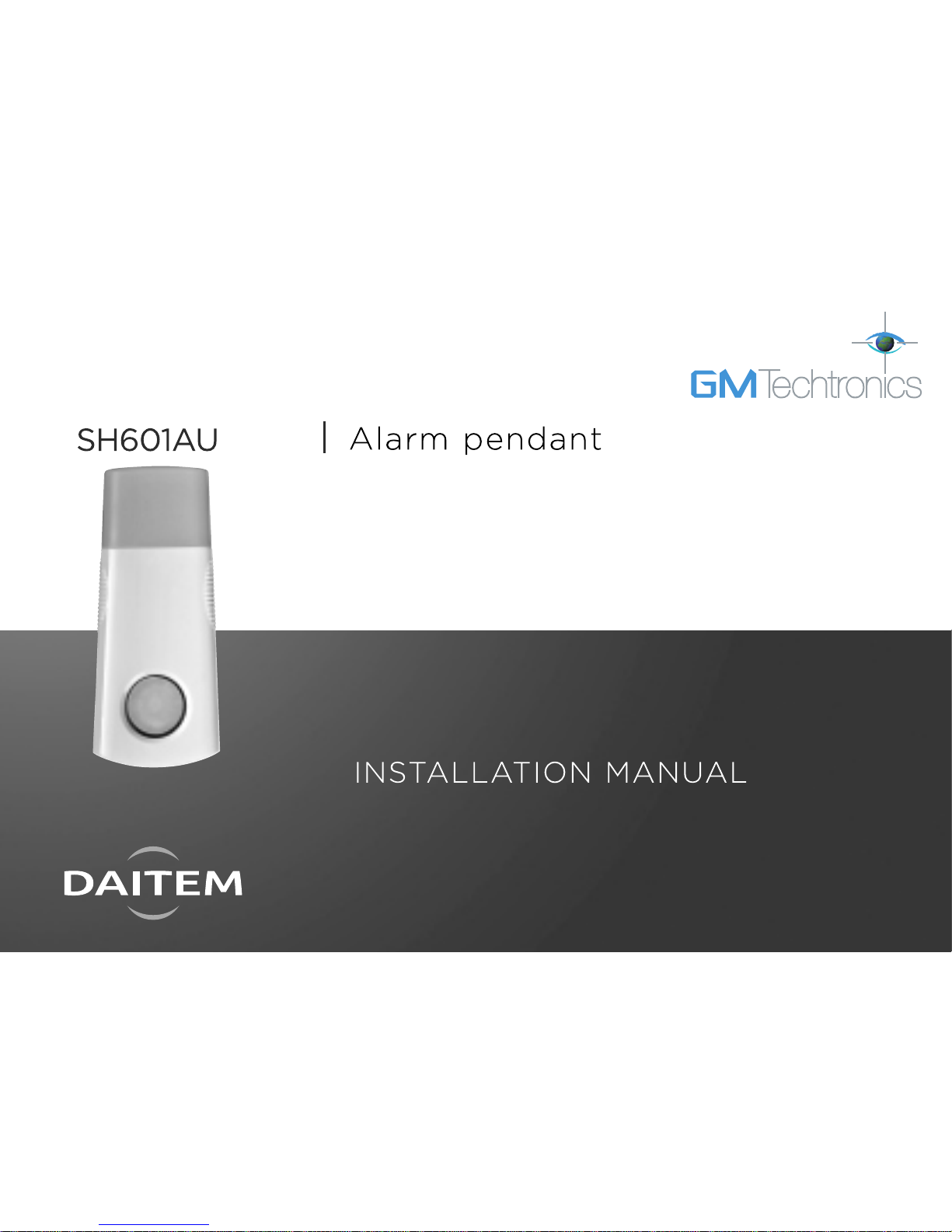
1. Introduction
● The pendant can be used to send messages 24 hours a day whether the alarm system is armed or disarmed.
Depending on its configuration, the pendant can be used to:
- transmit alarm messages to a remote monitoring service or to an individual’s phone via the telephone dialler,
- trigger an audible alarm via the system’s sirens,
- activate beeping on the alarm control panel.
● It can be worn:
- as a pendant using the neck cord,
or
- clipped to a belt using the holder. The holder can also be fixed to a wall.
● The pendant is compatible with TwinBand®alarm systems (434.5/869 MHz). It transmits radio messages to the
system (control panel or dialler) with which it has been programmed to operate:
1stconfiguration: with control panel
Control panel
or transmitting
panel
With
or without
dialler
)))))
)
)
)
)
)
2ndconfiguration:
without control panel
Dialler alone
)
)
))
)
3rdconfiguration: can be combined
with the first two and makes it
possible to use the pendant’s pushbutton to operate electrical devices or
lighting via control receivers or
remote-controlled sockets.
)))))
9 max
IMPORTANT: the pendant cannot be recognised directly by a dialler
alone SH511AX, SH512AX, SH513AX and SH514AX.
5
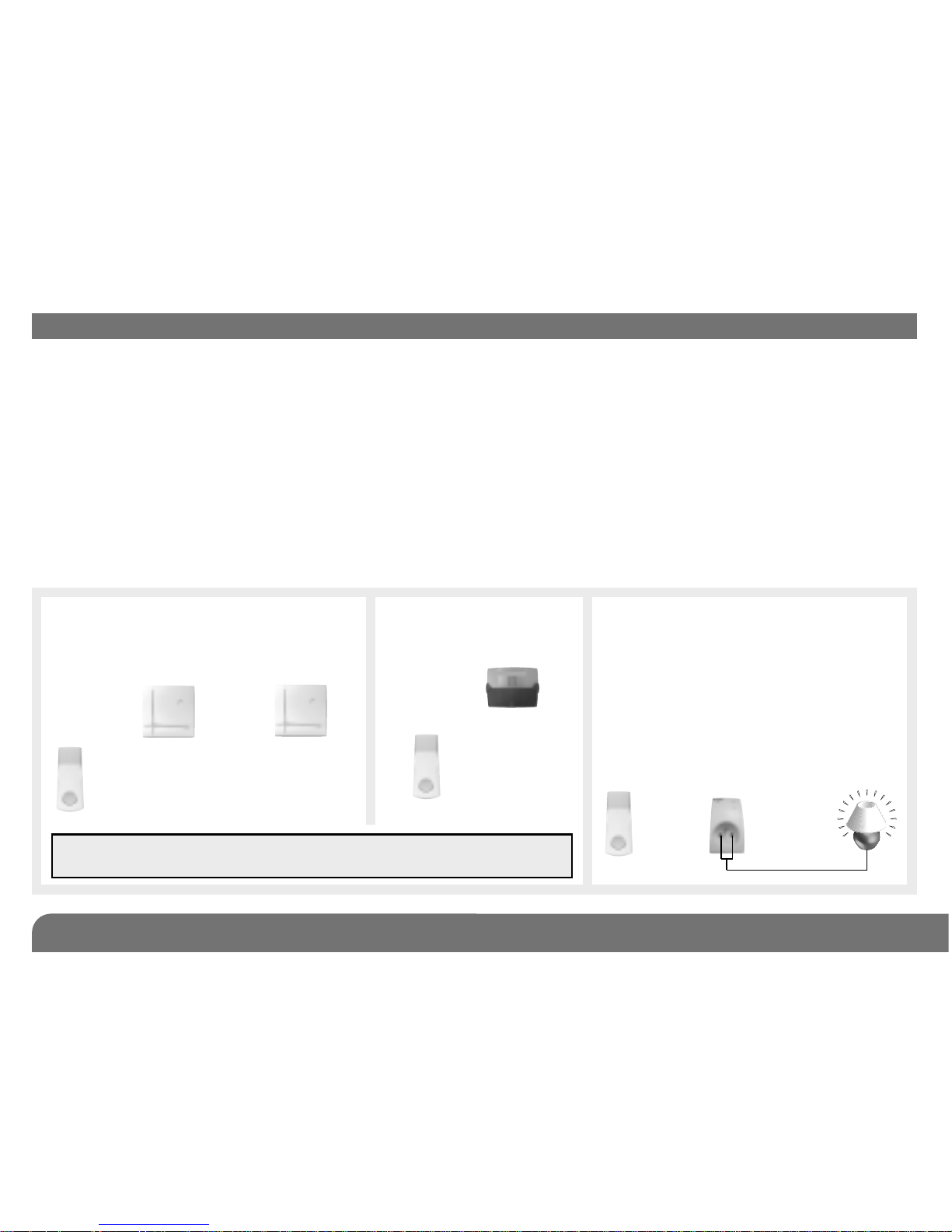
2. Operation
• The pendant can be activated by pulling
the sliding part down or by pressing on
the push-button (for more than 2 sec.). If
the sliding part stays in downward
position, the message is transmitted every
15 min.
• The pendant is factory-configured to send
the “Silent alarm” command. The sliding
part and push-button can be
programmed separately to send the
“Alarm” or “Local call” command
(see chapter on “Main configuration
operations”).
• The push-button can also be reprogrammed to send “Comfort”
type commands (see chapter on “Advanced programming”) in
order to:
- trigger a fire alarm,
- activate beeping or the door bell function on the control panel,
- operate an electrical device or lighting via external receivers or
remote-controlled sockets.
• The push-button LED shows that the pendant is working
properly:
- it indicates the battery status when the button is briefly pressed,
- it confirms the different radio commands transmitted by the
sliding part or the push-button:
* “Call” type (“Alarm”, “Silent alarm” or “Local call”): the LED
flashes red,
* “Comfort” type: the LED flashes green (push-button only).
Each command sent by pressing the push-button for longer
than 2 seconds (LED flashes green or red), is preceded by a
“battery status test” indicated by the LED briefly flashing red.
- it confirms configuration and indicates the function allocated to
the sliding part or push-button (in programming mode).
Quickfastener
Push-button
and LED
Sliding part
6
3. Preparation
3.1 Guarantee sticker to be returned
3.2 Product label to be kept
The product label, on the back page of the manual, should be kept. You
will be asked to provide it should you need to get in contact with the
technical support service regarding the pendant.
SH601AU
A1142A047879
Coller sur certif
Guarantee
sticker
Remove the pre-cut part of the
sticker and stick it to the guarantee
certificate in the user manual
supplied with the control panel. If
you are adding the siren to an
existing system, use the guarantee
sticker provided with this product.
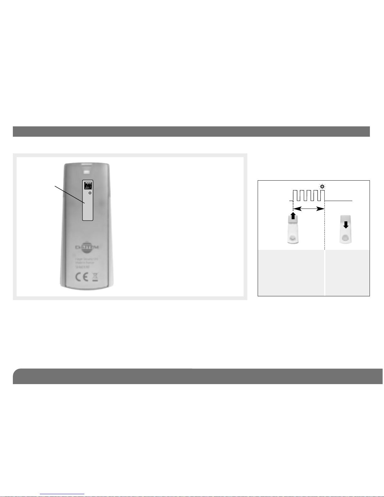
3.3. Activating the pendant
This operation should only be
performed when the pendant is first
used:
1. Pull the sliding part
down. The pendant
LED flashes for
roughly 2 seconds
and then goes out.
2 s.
LED OFF
LED ON
2. Push the
sliding part
up to close
it.
 Loading...