

DAITEM SH426AX Installation Manual


102
GB
Contents
1. Introduction ...................................... 103
2. Preparing the siren .......................... 104
2.1 Tooling required............................ 104
2.2 Opening the siren and
connecting the power supply....... 104
3. Recognition programming.............. 106
4. Setting the parameters ................... 107
4.1 Delayed alarm sounding
upon intrusion............................... 107
4.2 Setting the sounding parameters 107
4.3 Type of sounding.......................... 108
4.4 Sound level of arm and disarm
command indications................... 108
4.5 Transfer of arm and disarm
command indications................... 108
4.6 Indication of audible signals
and door bell................................. 108
4.7 Validation of radio link
in installation mode ...................... 108
4.8 Modification of speech
synthesis system language.......... 109
4.9 Triggering upon intrusion.............. 109
4.10 Protection system armed
indication .................................... 109
4.11 Alarm in armed presence
mode indication.......................... 109
4.12 Triggering following
a communication network
interruption ................................. 109
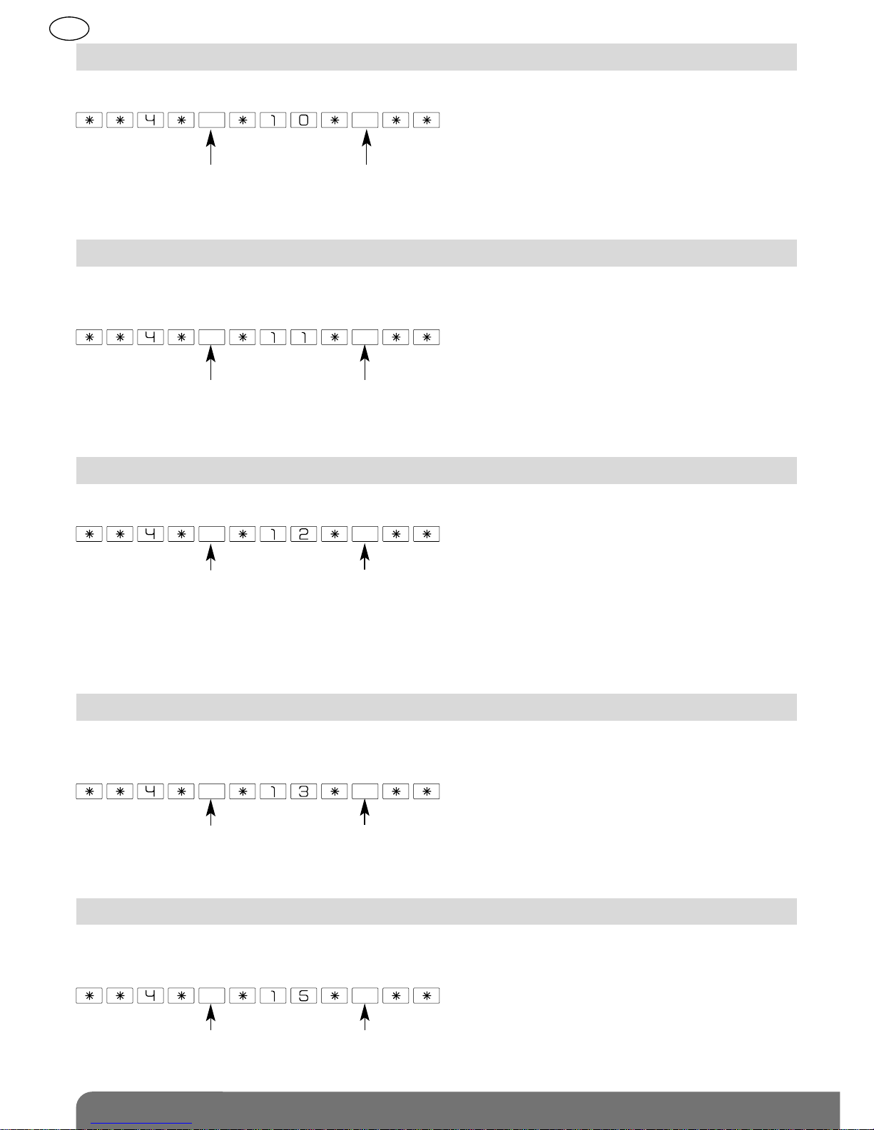
4.13 Radio tamper.............................. 110
4.14 Duration of flashing ................... 110
4.15 Indication of break-in
following intrusion ...................... 110
4.16 Visual localisation of flashing
strobe following break-in............ 110
4.17 Allocation of siren
to an alarm group ....................... 112
4.18 Type of indication ....................... 112
4.19 Anti-tamper switch triggering .... 113
4.20 Fire alarm indication................... 113
4.21 Checking..................................... 113
4.22 Deletion of parameters............... 113
5. Installing the siren............................ 114
5.1 Choosing the best place
to install the siren.......................... 114
5.2 Testing the radio range................. 114
5.3 Fixing the siren in place................ 115
6. Performing a real test...................... 116
7. Maintenance..................................... 117
7.1 Fault indications ........................... 117
7.2 Changing the battery.................... 118
8. Summary of parameters................. 118
9. Technical data .................................. 121
Recommendations
The user must not attempt to access the siren’s internal parts, except areas described in this
manual. If the user does access these parts, the product guarantee will be considered null and
void and DAITEM shall not be held responsible for any problems. Touching the siren’s internal
parts and/or electronic components can damage the product. Furthermore, the siren is designed
in such a way that these parts and components do not need to be accessed for operation or
maintenance purposes.
IMPORTANT: the siren’s sounding level can cause hearing disorders. Take the necessary
precautions before testing the product.
103
GB
1. Introduction
Following a command
Vocal message
Commands Disarm “bip, Off”
Arm “bip, Armed”
Armed Partial 1 or 2 “bip, Armed Partial 1” or “bip, Armed Partial 2”
Disarm Group “bip, Off”: if all the groups allocated to the siren are disarmed
“bip, Off Group X”: if only part of the groups allocated to the siren
are disarmed
Arm Group “bip, Armed”: if all the groups allocated to the siren are armed
“bip, Armed Group X”: if only part of the groups allocated
to the siren are armed
Arm Presence mode “bip, Armed Presence”
Door bell “ding dong”
Disarm under duress “bip, Off”
System
status query
Disarm “bip, Off”
Arm “bip, Armed”
Armed Partial 1 or 2 “bip, Armed Partial 1” or “bip, Armed Partial 2”
Disarm group “bip, Off Group X”
Arm Presence mode “bip, Armed Presence”
Alarms Intrusion when
presence mode armed
“bip, bip, bip, bip, intrusion Group X”
Entry delay “bip, bip, bip, bip, protection active”
Fire alarm loud sounding for 15 s then “Fire Alarm” (alternating)
Warning N°1 “Barking”
N° 2 “Beware, Intrusion alarm armed”
N°3 “Beware, Protected zone”
N° 4 “Intruder detected”
N° 5 “Intrusion, Alarm triggered”
Deterrence
Prealarm
Changing
siren modes
User test mode “bip, TEST_MODE”
Installation mode “bip, INSTALLATION_MODE”
User mode “bip, USER_MODE”
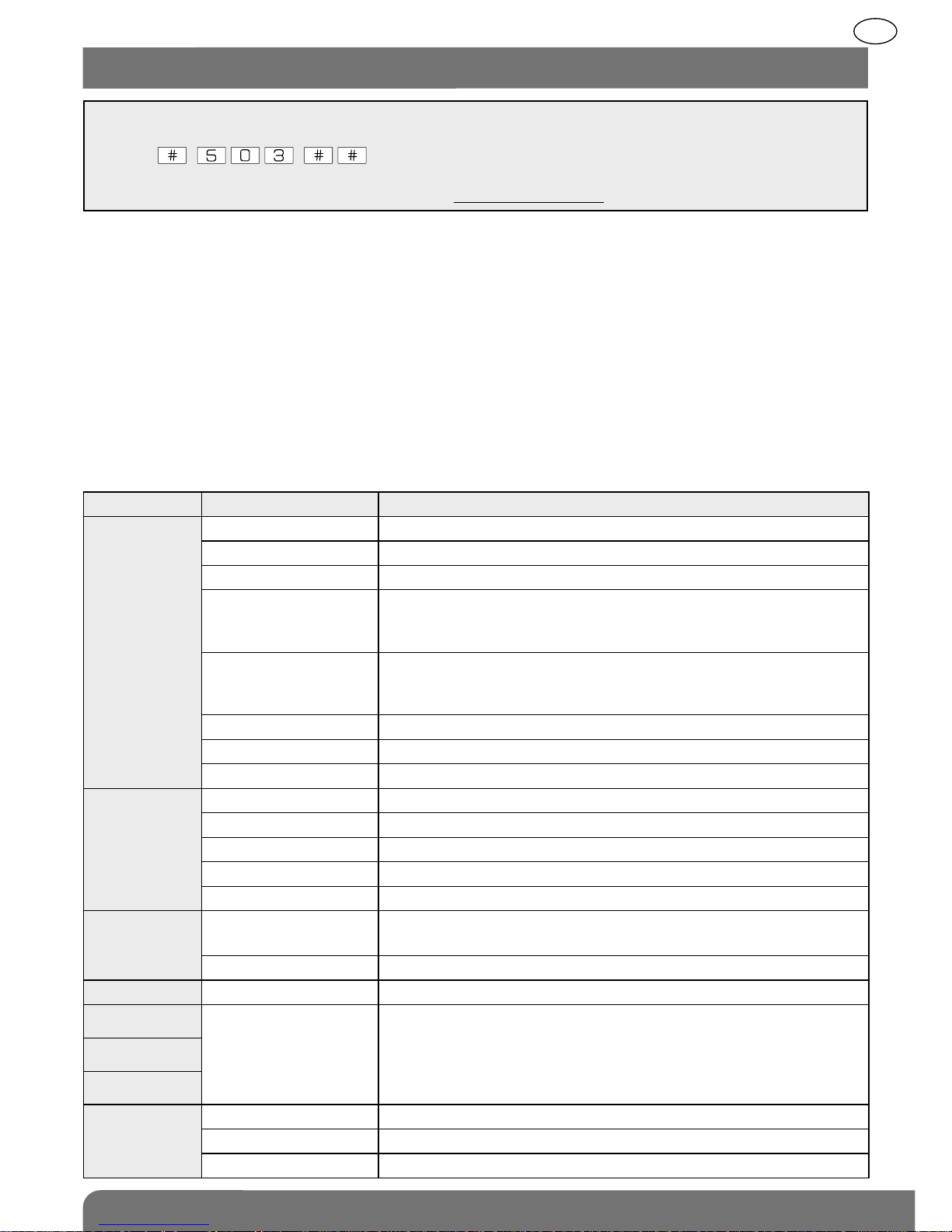
IMPORTANT
• Some functions are only available with versions 2.0.0 or later
(press on the control panel keypad to check the version).
• The operating differences with former ranges are described in the compatibility booklet
available in the Daitem installers section at www.daitem.co.uk.
depending
on chosen
parameters
}
In addition to the protection provided by the control panel with built-in siren and keypad, the
external siren with vocal messages and flashing strobe makes it possible to:
• deter intruders (vocal messages),
• alert neighbours (external sounding mode),
• easily locate the alarm (flashing strobe).
If a fire is detected, the siren is triggered for 5 minutes in fire sounding mode.
Thanks to its built-in transmitter, the siren informs the control panel when it has a battery
problem. If somebody attempts to pull the siren off the wall, it sounds and then triggers all
the alerts and deterrents via the control panel.
Vocal messages
The siren issues the following vocal messages:
104
GB
2. Preparing the siren
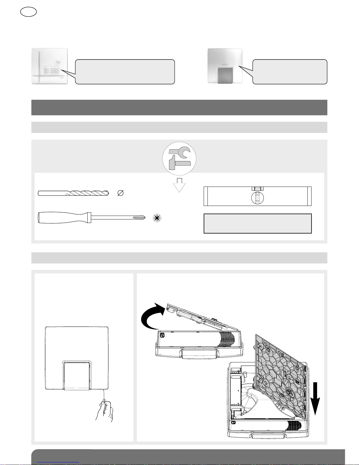
2.1 Tooling required
2.2 Opening the siren and connecting the power supply
IMPORTANT: the fixing screws
and wall plugs are not supplied.
6 mm
PZ 2
1. Insert a screwdriver into
the bottom right-hand
corner between the base
and the siren and apply
pressure to open the siren.
2. Place the siren on a flat surface, remove the base
by inclining it at a 45° angle (A)
and pull it downwards (B).
Example: The system is in Armed Partial 2 mode but the siren has a battery fault.
When the “system status query” order is sent from the keypad or remote control, the control
panel and siren issue the following vocal messages:
“Bip, Armed Partial 2,
bip, Fault, System”
“Bip, System_status, Armed
Partial 2, bip, 12/03 at 12:00, Fault,
Voltage, Remote_Control_Unit 1”
A
45°
B
105
GB
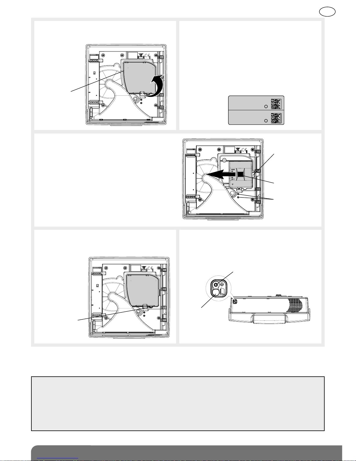
3. Lift up the screw cover and remove the
screw from its slot.
5. Position the power pack on the guide
rails.
6. Slide the power pack to the left until it
is locked into place.
8. Position the locking screw in its slot.
Coller sur certif
SH424AX
A12260A0963C
SH424AX
A12260A0963C
4. Guarantee sticker
Remove the pre-cut part of the sticker
and stick it to the guarantee certificate
in the user manual supplied with the
control panel. If you are adding the
siren to an existing system, use the
guarantee sticker provided with this
product.
Unlocking key
Locking screw
and battery
cover screw
Guarantee
sticker
Screw
cover
Bottom view of siren
Siren
opening
Locking screw slot
7. Reposition the battery cover and screw
it in place using one of the screws (A).
Screw slot
A
To remove the lithium power pack, press on the unlocking key and slide the pack towards the
right.
IMPORTANT
• When the siren is powered, it will issue a long beep and automatically switch to installation
mode (tamper mechanism disabled).
• If the siren does not respond as it should: - disconnect the power pack,
- wait for 2 minutes,
- reconnect the lithium power pack,
- check the siren issues a long beep as it should.

106
GB
IMPORTANT
• The siren does not need to be placed close to the control panel for recognition programming.
In fact, it is advisable to move it away from the panel (to a distance of at least 2 m).
• The control panel gives the siren a n° during recognition programming.
3. Recognition programming
Recognition programming allows the siren to be recognised by the control panel.
It must be done with the control panel and siren in installation mode. If they are not in
installation mode, enter:
then
master code installer code
Siren recognition programming sequence:
))))) )))))
Briefly press
the siren
“test” button
Press and hold “Off”
until the control panel
responds
The siren issues
an audible signal
to confirm
programming
The control panel
announces the siren n°.
“beeeep”“bip”
“bip, off,
control panel”
IMPORTANT: the control panel and siren issue three short beeps to indicate a programming
error. When this happens, perform recognition programming again from the start.
“bip, siren n°”
10 s max.
107
GB
4. Setting the parameters
The siren’s parameters are factory-programmed.
Each parameter can nevertheless be modified using the control panel keypad.
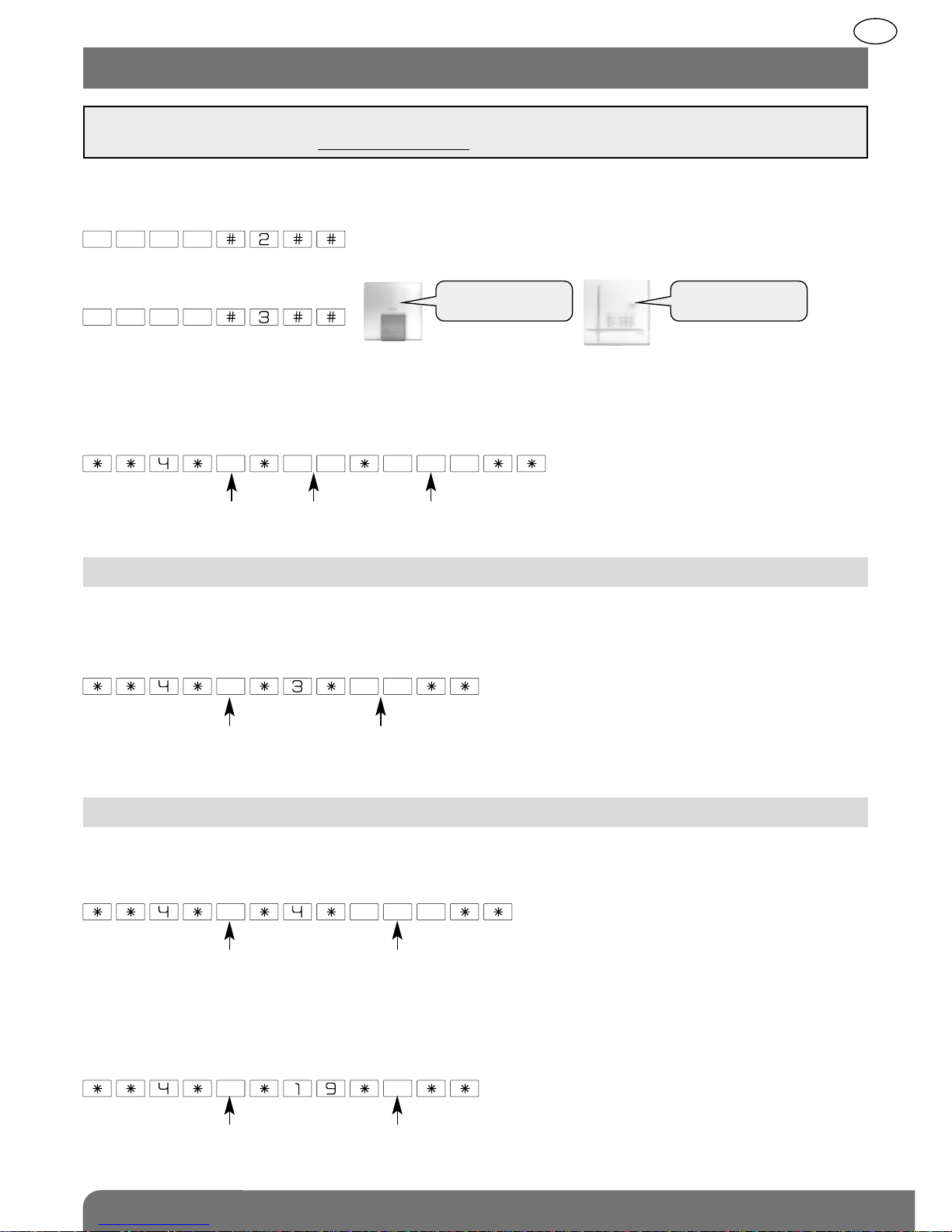
To set the siren’s parameters, first choose the parameters to be modified and then enter:
The control panel and siren must be in installation mode to set the siren’s parameters. If they
are not, enter:
then
master code
installer code
“bip, installation
mode”
Siren alarm sounding can be delayed by 60 seconds maximum. This gives users enough
time to disarm the system before the alarm siren sounds if, for instance, they have pressed
the wrong button. To delay sounding, enter:
Factory setting: 0 s
siren n° from 0 to 60 s
4.1 Delayed alarm sounding upon intrusion
parameter
n°
siren n° parameter
value
IMPORTANT: all parameter-setting must be done using TwinLoad®software available in the
Daitem installers section at www.daitem.co.uk.
4.2 Setting the sounding parameters
4.2.1 Duration of alarm sounding
To modify the duration of sounding, enter
Factory setting: 90 s
siren n° from 20 to 180 s
4.2.2 Level of sounding
To modify the level of sounding, enter:
Factory setting: 0
siren n° 0: normal
1: quiet
“bip, installation
mode”
108
GB
For greater user-friendliness, the sound level can be increased or decreased.
To do this, enter:
Factory setting: 4 = average
siren n° from 1 to 8
4.4 Sound level of disarm and arm command indications
0: internal
1: external
To modify the type of siren sounding, enter:
Factory setting: external
siren n°
4.3 Type of sounding
To modify the transfer of indications, enter:
Factory setting: 0
siren n° 0: disabled
1: sounding
2: vocal message (“bip, bip, bip, bip, Off or Armed”)
3: sounding and flashing
4: vocal message (“bip, bip, bip, bip, Off or Armed”) and flashing
5: flashing
4.5 Transfer of arm and disarm commands
This function is factory-set to be disabled. It can be enabled if required.
To do this, enter:
Factory setting: 0
siren n° 0: disabled
1: sounding
4.6 Indication of audible signals and door bell
This function is used to validate the radio link test in installation mode on 1 of the 2 radio
bands. To switch to 2 bands, enter:
Factory setting: 0
siren n° 0: validation on 1 of the 2 bands
1: validation on 2 bands
4.7 Validation of radio link in installation mode
 Loading...