

DAITEM SH320AU, SH340AU, SH380AU Installation Manual

2
Control panels manage:
• intrusion protection,
• technical protection,
• fire protection,
• tamper alerts,
• system device faults.
Protection against intrusion is ensured by intrusion detectors that have first been programmed for recognition by the control
panel.
The triggering of alarms depends on the system status and type of detectors activated.
The protection of individuals (e.g. silent alarm), and technical and fire protection devices operate 24 hours a day.
The control panel is protected against opening and removal.
If an alarm is triggered, the dialler and sirens are activated.
The control panel, which can control 2 to 8 separate protection groups (according to the type of control panel), is fitted with:
• an integral control keypad,
• a siren,
• a speech synthesis loudspeaker.
The different types of control panel are:
1. Introduction
Control panel reference Number of groups Number of detectors Number of user codes
SH320AU 2 20
SH340AU 4 40 32
SH380AU 8 80
IMPORTANT
• Some functions are only available with control panel versions 2.0.0 or later (enter on the control
panel keypad to check the version).
• Operational differences in relation to former ranges are described in the compatibility booklet available in the Daitem Installers
section at www.daitem.co.uk.
Depending on its reference, the transmission module uses
different media (see table opposite, unused media must be
declared).
When installing the product, it should be assumed that the
transmission module can have three transmission media:
PSTN, GSM/GPRS and ADSL.
The installation of an optional transmission module (not originally installed in the control panel) confers two additional
functions on the control panel.
Via its different communication networks, the transmission module makes the following possible:
1. remote alerts in case of intrusion or events occurring on the protected site.
• The control panel-dialler warns individual correspondents and/or a remote monitoring centre in the event of:
- intrusion,
- technical alarms,
- fire alarms,
- tamper alerts,
- faults in one of the system devices.
• In the event of intrusion, the control panel-dialler makes the following remote operations possible:
- listen-in and speak-out/talk-back,
- visual alarm confirmation via the transmission of images or films from the image transmission motion detectors
and/or compatible IP cameras installed on the protected site.
2. remote access to the protected site:
• alarm system operation,
• parameter-setting,
• checking.
The transmission modules are:
Module
reference
Transmission media
SH501AX PSTN -
Ethernet
(ADSL)
SH502AX - GSM/GPRS
SH503AX PSTN GSM/GPRS
SH504AX - -
GSM/
GPRS
ETHERNET
(ADSL)
fi Only concerns transmission modules using the media indicated
(example here: GSM/GPRS and Ethernet (ADSL)).
3
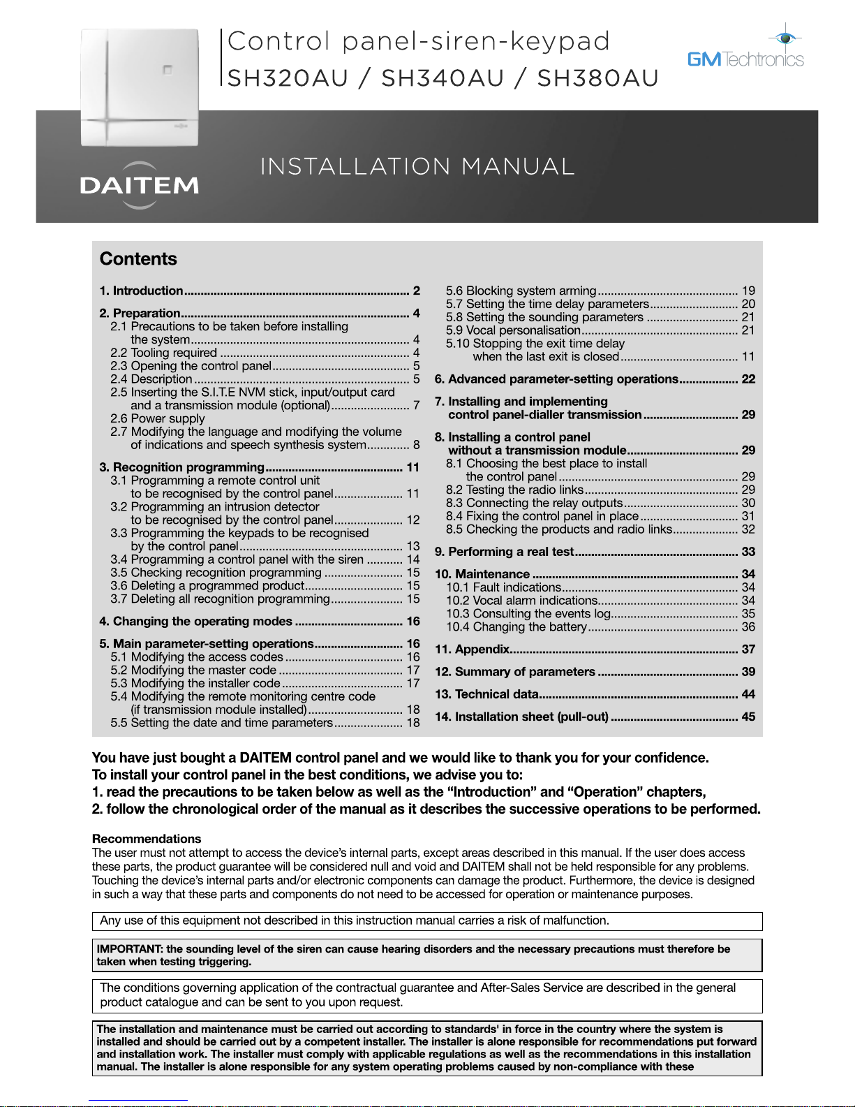
System responses:
Intr ud er ad va nc es f u r t h e r on to pre mi se s
(1) If transmission module installed.
(2) Loud triggering if Prealarm only confirmed.
Confirmation of Intrusion alarms
Intrusion alarms can be confirmed if they are preceded by a 1stevent within a specific lapse of time.
The intrusion attempt is confirmed if the intruder is detected twice leading to specific control panel messages.
IMPORTANT: confirmation is validated when 2 events in a row are detected by 2 different detectors.
Confirmation of intrusion
1
st
ev
ent
2
nd
event
Intrusion confirmed
less than 15 min
• Prealarm
• Intrusion
• Intrusion
WARNING
• Control panel: 2 s audible beeps
• External siren, 3 choices possible:
- discreet sounding triggered (2 s) + strobe flashes (5 s)
- discreet sounding triggered (2 s)
- strobe flashes (5 s)
DETERRENCE
• Control panel: 5 s audible beeps
• Telephone transmission (choice) (1)
• External siren, 3 choices possible:
- discreet sounding triggered (5 s) + strobe flashes (5 s)
- discreet sounding triggered (5 s)
- strobe flashes (5 s)
(
((
((
(
(
(
(
(
(
((
((
(
(
(
(
(
PREALARM
• Control panel: siren triggered for 15 s + telephone transmission (choice) (1)
• External siren, 3 choices possible:
- discreet or loud sounding triggered (2) + strobe flashes (15 s)
- discreet or loud sounding triggered (15 s)
- strobe flashes (15 s)
(
((
(
(
(
(
(
(
(
INTRUSION
• Control panel: siren triggered for 90 s + telephone transmission (1)
• External siren: loud sounding + strobe flashes for 15 min.
(
((
((
(
(
(
(
(
1
st
ev
ent
2
nd
event
Intrusion confirmed
less than 15 min
• Prealarm • Intrusion
4
2.1.1 Site diagnosis before installation
Before installing the system and deciding on the best place for each product, a diagnosis of the site to check its radio
transmission range must first be performed. It is especially important to carefully check a number of specific points
including those relating to the type of professional premises:
• distances or surfaces to be monitored: generally bigger on professional premises than residential sites,
• materials used: metallic materials are often used in walls and partitions,
• modifications to the internal configuration of the home or premises: these can be frequent (addition of walls or
furniture, storage of materials, etc.).
The range has been especially studied for all of these cases.
Nevertheless, system reliability does depend on the place where products are installed.
This is why we recommend performing a detailed survey of the site, with a focus on the following points:
• All metallic materials represent an obstacle to the propagation of radio transmissions and are likely to have a
considerable impact on the link between two products.
Thus, the following cases must be avoided:
- installation of products in the immediate vicinity of apparent or hidden metallic materials (reinforced concrete walls for
example), etc.,
- metal walls, shelves, frames or trellises between a product and the control panel or a radio repeater relay.
- installation of the control panel or a relay in a plant room or in the immediate vicinity of other electrical or computer
products.
If the above environments cannot be avoided, it is highly advisable to install a radio repeater relay to get around these
obstacles.
• Any modification to the internal configuration or layout of the home or premises is likely to have a considerable
impact on the link between two products:
- reorganisation of the premises (addition of walls or furniture, etc.),
- reorganisation of a workshop or storage area,
- storage areas with variable capacities (notably metallic materials),
- mobile metallic doors or partitions,
- parking of vehicles (handling trucks, vehicles in a garage).
In all cases where such variations are likely, it is highly advisable to use a radio repeater relay to reinforce the link and get
around potential obstacles between various products and the control panel.
We also advise you to draw users’ attention to this fact and to check the radio links again every time the configuration of the
premises is changed.
2.1.2 Checking radio links during installation
To ensure long-lasting reliability of the radio links, it is essential to check each one in Installation mode once all the products
have been installed (see chapter on “Checking the products and radio links” in this manual).
If the layout of the premises is likely to be changed, it is advisable to check products and links for every possible
configuration.
2.1 Precautions to be taken into account before installing the system
2. Preparation
IMPORTANT: if these instructions are not complied with, random and frequent radio link losses between the various products
may be detected.
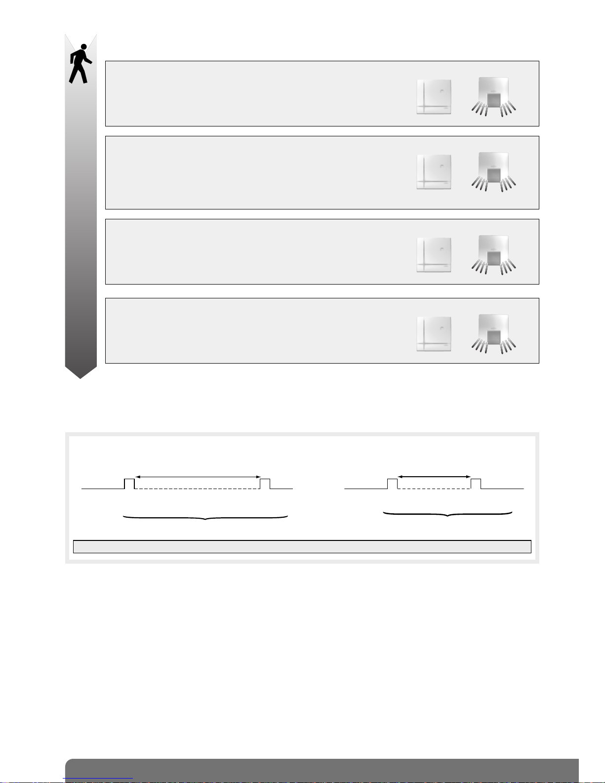
2.2 Tooling required
6 mm
3.5 mm
The fixing screws
and plugs are not supplied.
PZ 2
5
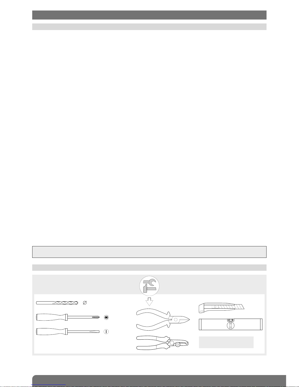
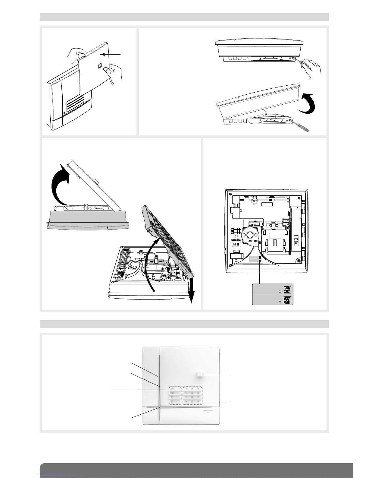
2.4 Description
Control panel
Loudspeaker
12 programming buttons
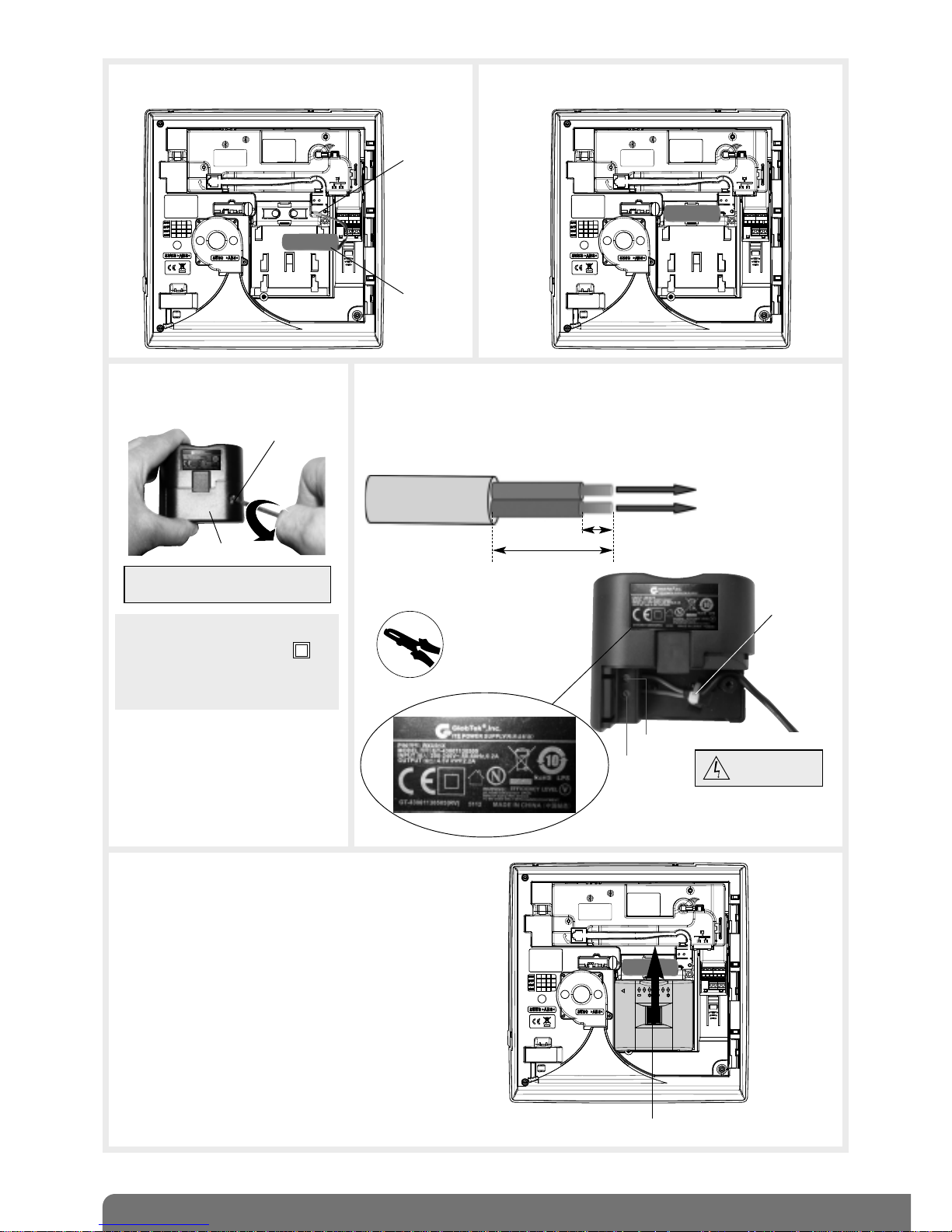
2.3 Opening the control panel
Cover
1. Remove the cover. 2. Insert a screwdriver into
the bottom right-hand side
(A) of the base and push
on it in order to open the
control panel (B).
A
B
3. Place the dialler on a flat surface and then remove the base
by inclining it an angle of 45° and pulling it downwards.
4. Guarantee sticker
Remove the pre-cut part of the guarantee
sticker and stick it to the guarantee certificate
inside the user manual supplied with the
control panel. If you are adding to an existing
system, use the guarantee certificate supplied
with this product.
Coller sur certif
SH380AF
D12250A7F00
SH380AF
D12250A7F00
45°
Side view
4 customisable command buttons:
• armed
• off
• armed partial 1
• armed partial 2
Blue light
45°
Coller sur certif
SH380AU
D12250A7F00
SH380AU
D12250A7F00
Microphone
Three-colour LED
6
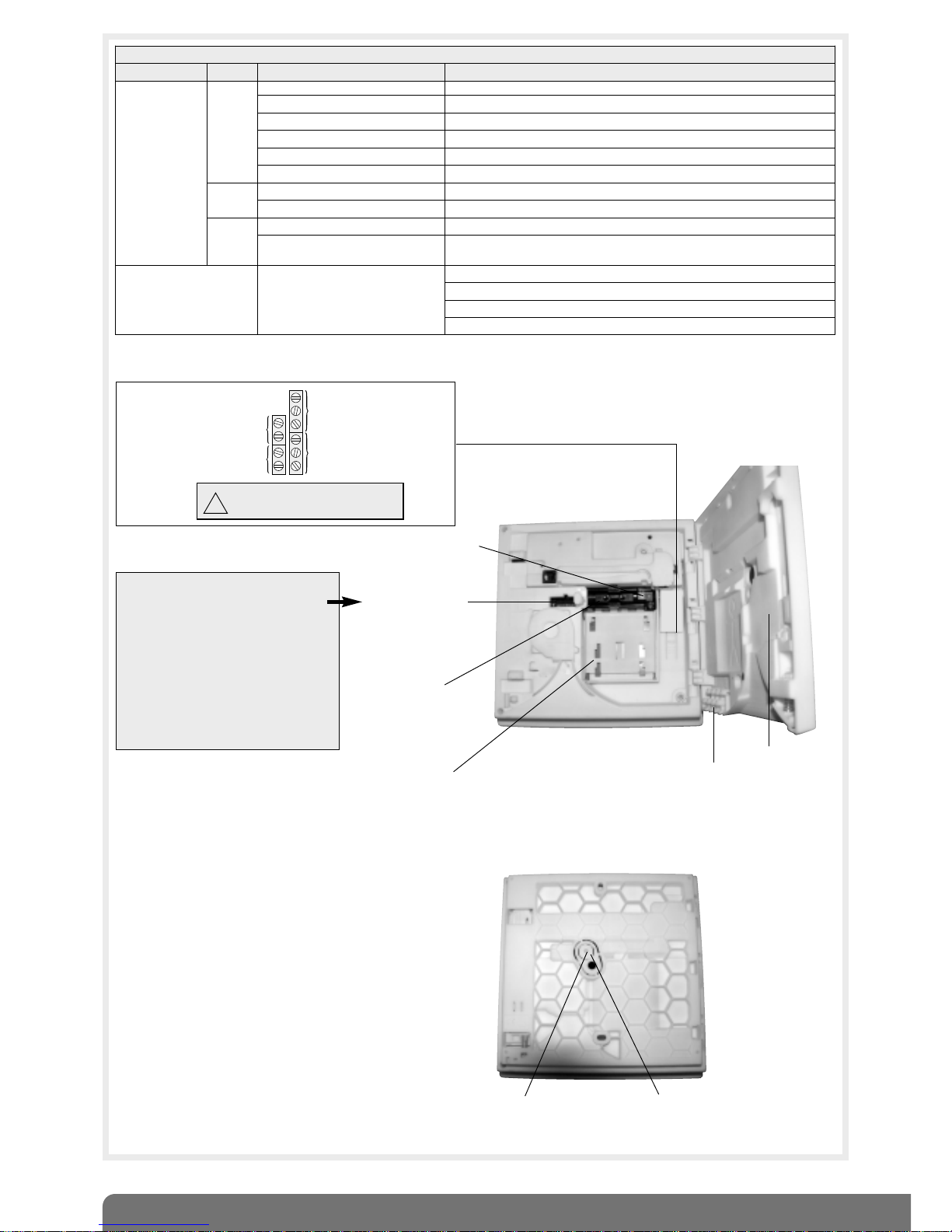
Compartment for input/output card (optional)
CAUTION: the system is sold without
S.I.T.E. module, it is an option and
allows:
• the storing of the parameters of all
the products of the system,
• the storing of the recorded vocal
messages.
IMPORTANT: connection and the
disconnection of the S.I.T.E module
must.
ONLY be done when the Control
panel is UNPOWERED !
Tamper pin
Base
Slot for cable
clamp supplied in
bag of accessories
Compartment:
- lithium power pack
or
- internal mains power module
(not supplied)
Compartment
for Li-Ion rechargeable
back-up battery
(optional)
Compartment for
S.I.T.E. NVM stick
(optional and not
compulsory)
Detachable washer
Inside view
Rear view
1 x 2-point connector
for rechargeable
back-up battery
Do not connect the 230 V
mains to relay outputs.
!
Control panel
relay 2 output
Relay output:
0.5 A 24 V AC
or 1 A 30 V DC
NC type inputs
for connecting
potential-free
conductor only
Hardwired
detector input
Tamper
input
Control panel
relay 1 output
J2
J1
J5
J6
{
}
LED indications
LEDs LED status Meaning
Three-colour LED
red
steady button pressed or line occupied
continuous rapid flashing operation blocked when powered
12 s maximum rapid flashing connection test, date and reference
1 flash every 5 s permanent indication of test mode
2 flashes every 10 s permanent indication of installation mode
3 rapid flashes error
green
steady for 10 seconds valid access code
steady recording of 10 s maximum voice message
orange
rapid flashing during message saving (1) (no other vocal personalisation possible)
1 flash every 20 s
system fault (power fault, media fault (2) or loss of product radio link)
in user mode and when system is disarmed
Blue light
modulated indication
mode change: installation, test and use
arming or disarming
system status command
one of the 4 customisable keys pressed (arm, disarm, arm partial 1 and 2)
(1) If SITE NVM stick or transmission module installed.
(2) If transmission module installed.
7
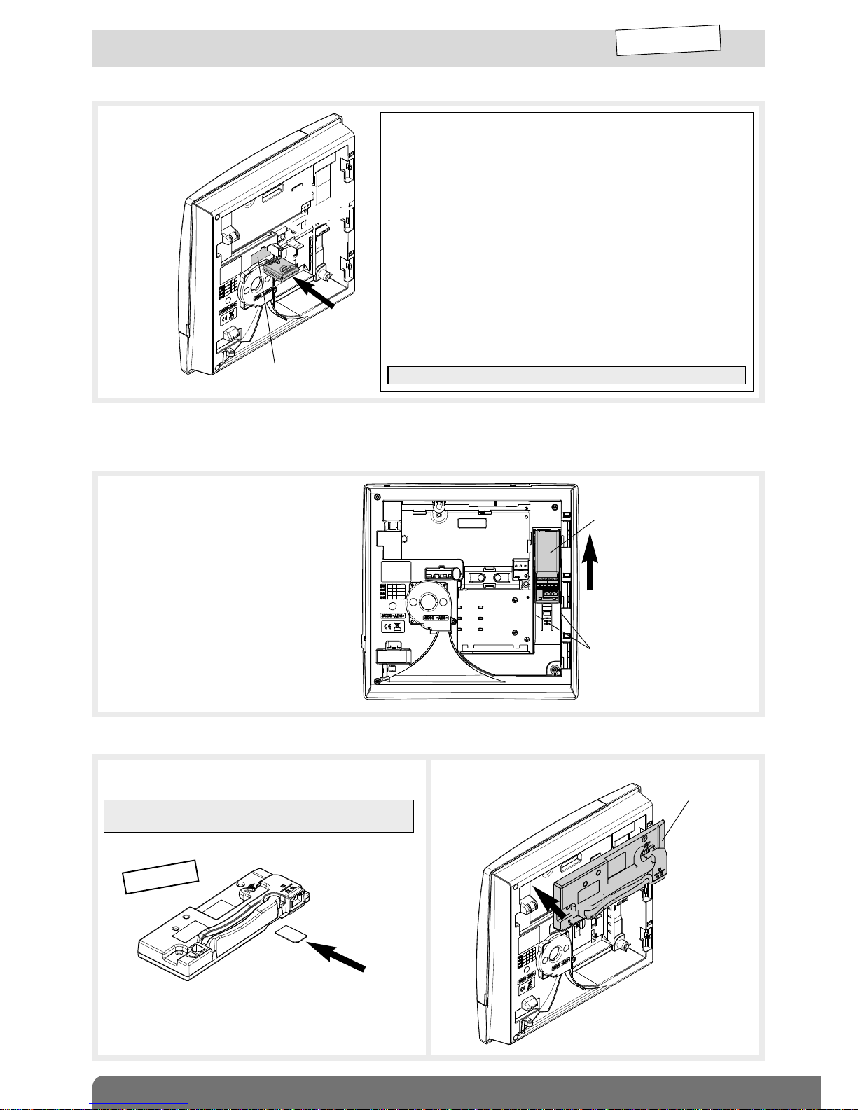
2.5 Installing the S.I.T.E. NVM stick, input/output card
and transmission module (optional)
2.5.2 Installing the input/output card (with power off)
1. Position the input/output card on the
guide rails.
2. Slide the input/output card to the top
until it is locked into position.
INSTALLATION
MODE
Input/output card
Guide rails
2.5.1 Installing the S.I.T.E. NVM stick (with power off)
2.5.3 Installing the transmission module (with power off)
2. Clip the transmission
module on to the top
part of the control
panel.
Transmission
module
1. Insert the SIM card into its compartment following the
direction indicated below the module.
GSM/GPRS
IMPORTANT: the transmission module is only compatible
with mini SIM cards.
If using an input/output card and a transmission module, the input/output card must be installed first.
Insert the S.I.T.E. stick in the
appropriate compartment
making sure it is the right
way round.
The S.I.T.E. Module allows:
• saving all the parameters and personalised vocal messages and
loading this information into the Control Panel without the need
to reprogram the system.
• the transfer of the personalized vocal messages of the Control
Panel into a separate transmitter.
If the S.I.T.E. module is virgin and the power station is already
configured, the parameter setting and the programming
information is transferred into the S.I.T.E. module.
If the Control Panel is virgin and S.I.T.E. module is full, the data
stored in the S.I.T.E. module is transferred into the Control Panel.
If the Control Panel is configured and S.I.T.E. module is also full,
and the 2 sets of data are different the system announces an
anomaly, and start-up is delayed until the S.I.T.E. module
becomes compatible by updating itself with the data from the
Control Panel. The assumption is that the Control Panel data is
correct.
CAUTION: the transfer time of the data can be long.
S.I.T.E. module
compartment
8
2.6 Power supply
INSTALLATION
MODE
Type of power supply to be installed according to media used:
• 2 x (3.6 v, 13 Ah) lithium power pack, BatLi 22
• Li-Ion = 3.7 V/1.2 Ah Li-Ion rechargeable back-up battery
• Mains power module = 200-240 VAC 50-60 Hz / 4.5 VDC 2.2 A internal mains power module
When using the transmission module card:
Accessories and power supplies to be used
The accessories and power supply(ies) needed to install the control panel-dialler depend on the type of transmission module and
media used. Before going out to the site, installers must make sure they have the additional accessories and power supply(ies)
listed in the “Appendix” chapter (besides any accessories that are supplied with control panel and transmission module).
Declaring unused media
To prevent faults from occurring due to line cuts or the absence of transmission media in user mode, unused media must be
declared. This parameter-setting operation is explained in the installation manual common to the control panel-dialler and
the stand-alone dialler: “Parameter-setting and implementation of transmission with transmission module/chapter on
“Main parameter-setting operations for the transmission module/Declaring unused media”.
Indication of power faults on power-up
Please note:
• If the main power supply has to come from the mains power module:
- a sufficiently charged Li-Ion back-up battery must be installed in case the control panel-dialler issues the voice message
“Fault, Accumulator Voltage, Control panel”, and the red LED flashes until the battery has been properly connected.
- if there is a mains power supply problem, the control-panel dialler issues the voice message “Fault, Battery Voltage, Control
panel”.
• If the main power supply comes from the BatLi22 lithium power pack:
- the Ethernet (ADSL) media will not be operational,
- the GSM/GPRS media will be operational on condition that the Li-Ion back-up battery has been installed. In this case
(powered without mains), the GSM/GPRS media will be configured by default for outgoing calls only.
If an improper power supply is used with the transmission module connected this will lead to an error indication following
power-up.
What to do if?
Red LED Voice message Solutions
Constant
rapid
flashing
“fault, power supply,
transmitter plug”
use the tables in the “Appendix/Accessories and power supplies to
be used” chapter to check compatibility between the transmission
module media and the control panel-dialler power supply.
“fault, transmitter plug” check the transmission module has been properly installed.
“fault, battery voltage,
control panel”
check the state of the main power supply: BatLi 22 lithium power
pack or mains power module depending on the case.
“fault, accumulator
voltage, control panel”
if the power supply is from the mains, check that the Li-Ion back-up
battery has been installed and is properly charged.
Media used
Control panel
without
transmission
module
Control panel with telephone transmission module/media available
SH501AX
PSTN+ Ethernet
(ADSL)
SH502AX
GSM/GPRS+
Ethernet (ADSL)
SH503AX
PSTN+GSM/GPRS+
Ethernet (ADSL)
SH504AX
Ethernet
(ADSL)
PSTN+Ethernet
(ADSL)
/
mains power
module + Li-Ion
/
mains power module + Li-Ion
/
GSM/GPRS+
Ethernet (ADSL)
/ /
mains power module
+ Li-Ion
/
PSTN+GSM/GPRS
+Ethernet (ADSL)
/ / / /
(PSTN+GSM/GPRS)
only
/ / /
• BatLi 22 + compulsory Li-Ion
or
• mains power module + Li-Ion
for GSM incoming calls
/
PSTN only /
• BatLi 22
or
• mains power
module + Li-Ion
/
• BatLi 22
or
• mains power module + Li-Ion
/
GSM/GPRS only / /
• BatLi 22 +
compulsory Li-Ion
or
• mains power module
+ Li-Ion
• BatLi 22 + compulsory Li-Ion
or
• mains power module + Li-Ion
for GSM incoming calls
/
Ethernet (ADSL) only / mains power module + Li-Ion
No remote
transmission module
BatLi 22
or mains power
module
/ / / /
9
IMPORTANT
• Use of the back-up battery is often compulsory for operation with a transmission module (see chapter 2.6 Power supply).
• the back-up battery is recharged on the control panel and is designed to back up the main power supply.
• Connect the back-up battery before the lithium power pack or internal mains power module.
• The back-up battery must be connected with the power off.
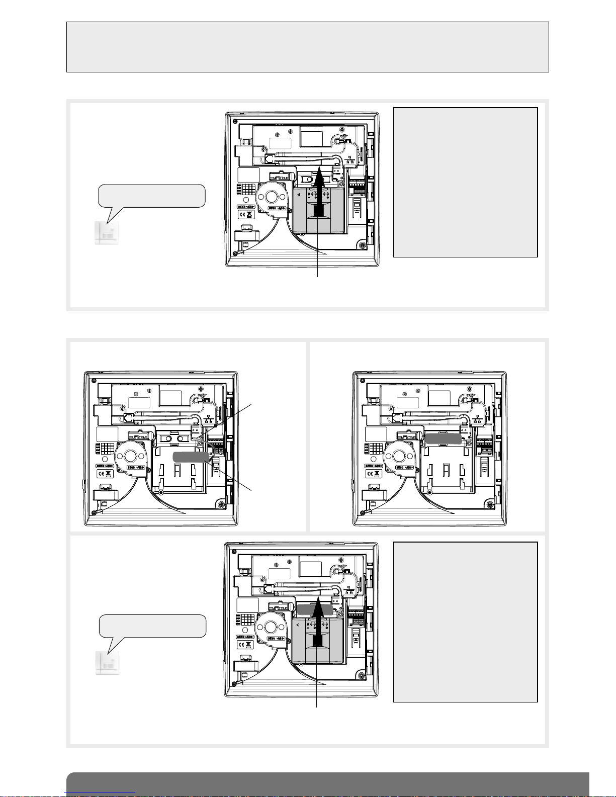
2.6.1 When using the lithium power pack (supplied)
1. Position the lithium power pack on
the guide rails.
2. Slide the lithium power pack to the
top until it locks into position.
3. After power-up you will hear the
control panel voice message:
To remove the lithium power pack,
press on the unlocking key and slide
it downwards.
IMPORTANT
• If the dialler does not respond as it
should:
- disconnect the lithium power pack
and then the back-up battery,
- wait for 2 min,
- reconnect the back-up battery
and then the lithium power pack,
- check the correct voice message
is issued.
If there is a problem, the control
panel will issue the following
message: “Fault, battery voltage,
control panel”.
• On power-up, the control panel is
automatically in installation mode.
“bip, installation mode”
Locking key
2.6.2 When using the BatLi 22 lithium power pack and the Li-Ion rechargeable back-up battery
1. Connect the rechargeable back-up battery
to the 2-point connector.
2. Clip the back-up battery into its compartment.
3. Position the lithium power pack on
the guide rails.
4. Slide the lithium power pack to the
top until it locks into position.
5. After power-up you will hear the
control panel voice message:
To remove the lithium power pack, press on the unlocking key and slide it downwards.
IMPORTANT
• If the dialler does not respond as it
should:
- disconnect the lithium power pack
and then the back-up battery,
- wait for 2 min,
- reconnect the back-up battery
and then the lithium power pack,
- check the correct voice message
is issued.
If there is a problem, the control
panel will issue one of the fault
messages (see Indication of power
faults on power-up on previous
page).
• On power-up, the control panel is
automatically in installation mode.
“bip, installation mode”
3.7 V/1.2 Ah
back-up
battery
2-point
connector
Locking key
10
2.6.3 When using with the mains power module and Li-ion rechargeable battery (not supplied)
5. Position the mains power module on the guide rails.
6. Slide the module upwards until it locks into position.
Locking key
3. Loosen the internal mains power
module locking screw.
4. • Connect the mains power cable type H05VVF 2 x 0.75 mm2,
twin with diameter between 5 mm and 7.5 mm to the terminal block.
• Install a cable clamp.
• Put the cover back and tighten the closing screw.
Cover
Locking screw
230 V
mains cable
clamp (not
supplied)
Electrical
shock hazard
1. Connect the rechargeable back-up battery
to the 2-point connector.
2. Clip the back-up battery into its compartment.
Battery
2-point
connector
IMPORTANT: only use 4.5 V DC
power module
RXU01X internal mains power module:
200-240 VAC
50-60 Hz / 4.5 VDC 2.2 A
double insulation symbol,
220 V power supply
without earth connection)
Connect to terminal “N”
of the terminal block
(blue cable)
Connect to terminal “L”
of the terminal block
7 mm +/-1
28 mm +/-2
Strip 28 mm of the outer cover, and 7 mm of insulation
from the inner cores
Terminal L
Terminal N
11
Recognition programming makes it possible for a product (remote control unit, detector, etc.) to be recognised by the control
panel. The control panel allocates a number to each product programmed for recognition in chronological order of
programming.
For products that need to be relayed, control panel recognition programming must be done via a radio repeater relay (see
Radio repeater relay installation manual).
3. Recognition programming
IMPORTANT
• To perform recognition programming operations, the control panel must be in installation mode.
• During recognition programming, the product to be programmed for recognition does not need to be close to the control
panel. In fact, it is advisable to move it at least 2 metres away from the control panel.
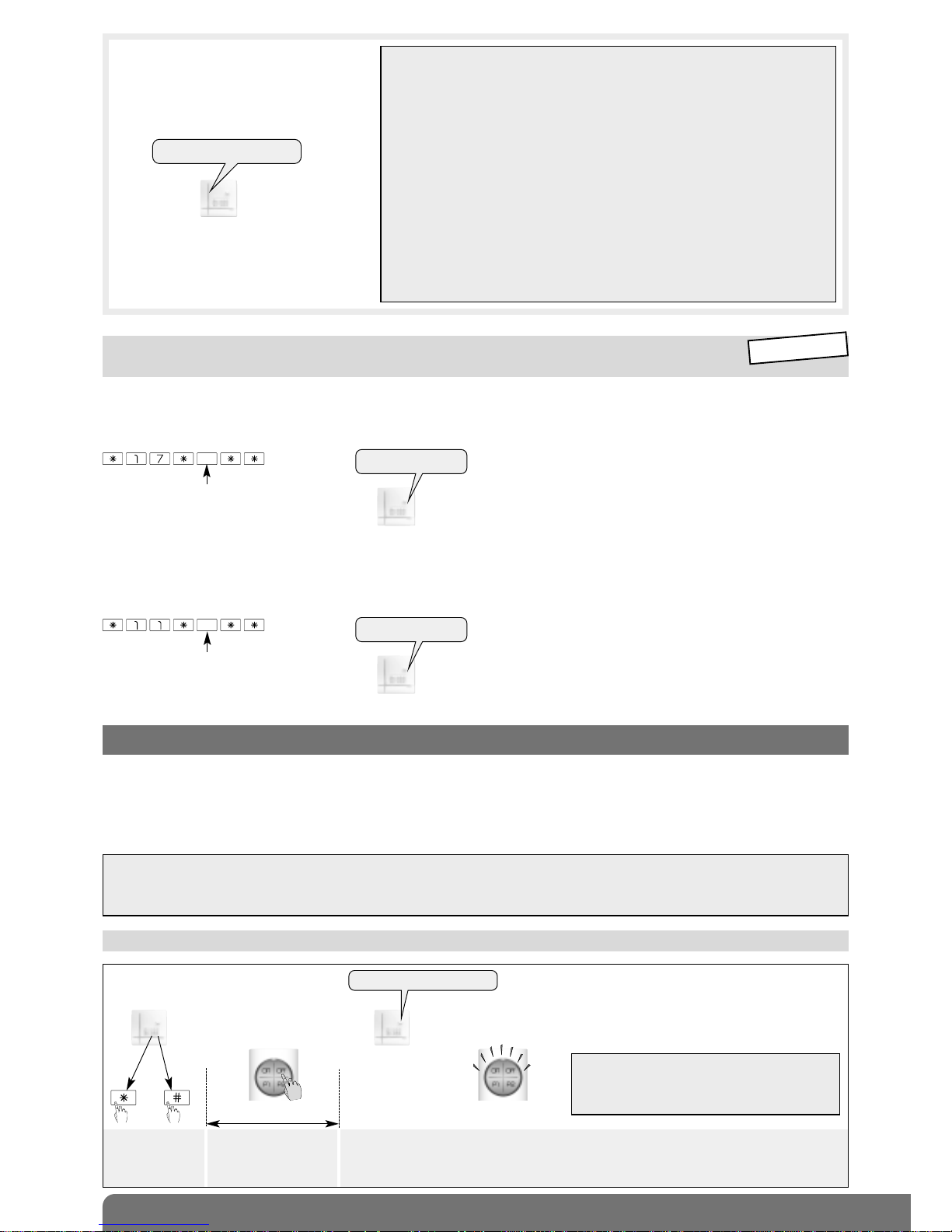
3.1 Programming a remote control unit to be recognised by the control panel
Press and hold “Off”
(orange LED flashing)
until the control panel
responds
The control panel issues a voice
message and the remote control
unit LED lights up steady green
for 1.5 s to confirm recognition
))
)
)
)
10 s max.
then
“Bip, remote control unit X”
• Language
Depending on the user, you can replace the original system language, English, with a different language:
To select the language, programme:
Factory: English
• Setting the indication and speech synthesis volume
The level can be adjusted from 1 to 8.
Factory: average sound level = 4
Sound level from 1 to 8
2.7 Modifying the language and modifying the volume of indications
and speech synthesis system
0: French
1: Italian
2: German
3: Spanish
4: Dutch
5: English
“bip + chosen
language”
“bip + chosen level”
INSTALLATION
MODE
IMPORTANT: the control panel issues three
short beeps to indicate a programming error.
When this happens, perform recognition
programming again from the start.
7. Connect the other end of the mains
cable to the mains power via an
unswitched fused connection box.
8. Following power up, the control panel
will issue the voice message:
IMPORTANT
• If the
control panel
does not respond as it should:
- disconnect the mains power supply then disconnect the power module,
- disconnect the back-up battery,
- wait for 2 min,
- reconnect the back-up battery,
- reconnect the power module and then the mains power supply,
- check the control panel message.
• On power-up, the control panel is automatically in installation mode:
- if the battery is not detected, the control panel issues the voice message
“fault, accumulator voltage, control panel”, and the red LED flashes until
the battery has been properly connected,
- if there is a mains power supply problem, the control-panel issues the
voice message “fault, battery voltage, control panel”,
- if using the Mains power supply (RX01X) and requiring to change the type
of power supply (BatLi22) this MUST be done totally UNPOWERED. It is
IMPERATIVE to disconnect the standby battery (Li-Ion 3.7 V/1.2 AH) and
wait for 2 minutes before re-connecting power.
To remove the module, press the
unlocking key and slide it downwards.
“bip, installation mode”
Press *then # on
the control panel
keypad
12
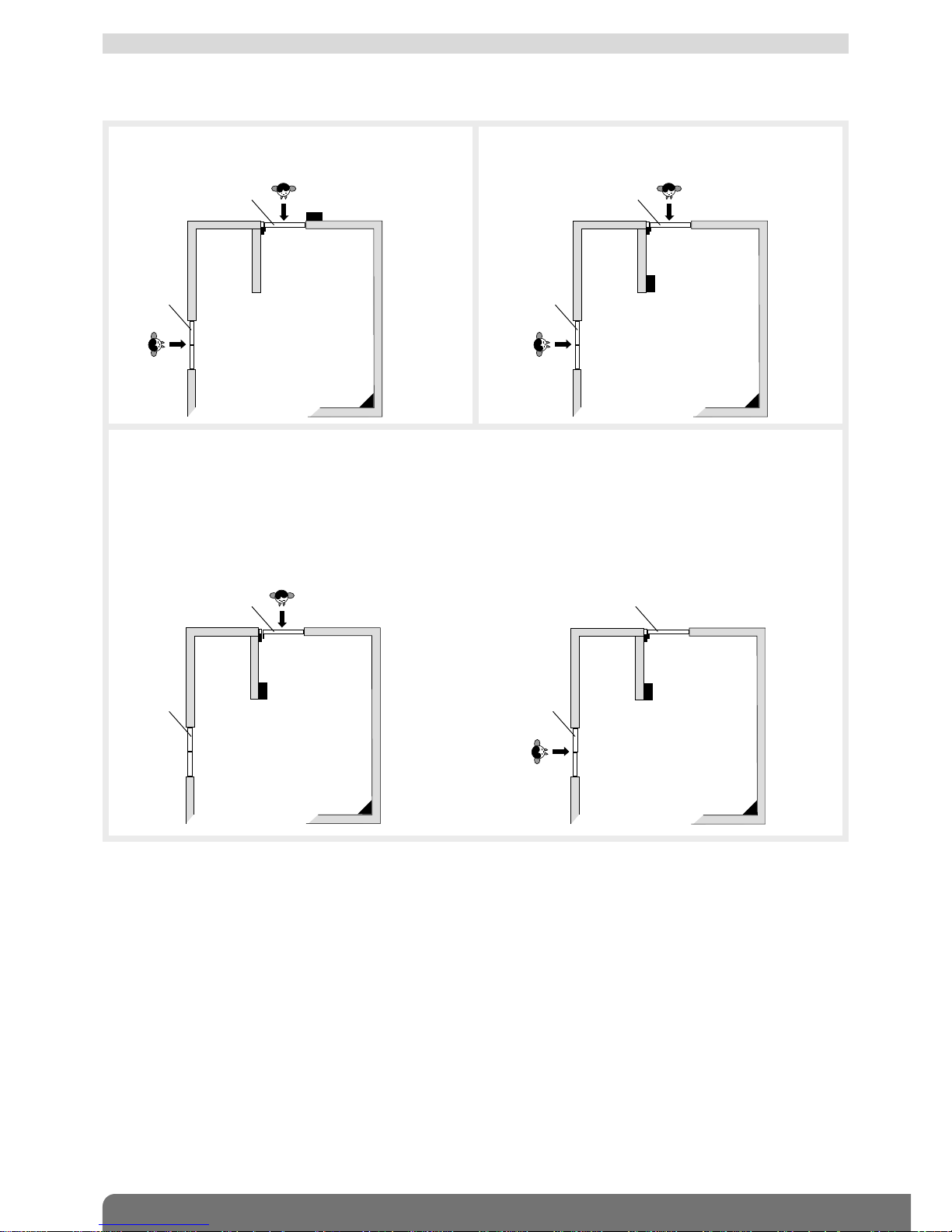
Different types of triggering possible: • immediate,
• time-delayed,
• combined.
Immediate triggering
In the event of intrusion, the alerts and deterrents are
immediately triggered.
3.2 Programming an intrusion detector to be recognised by the control panel
Door/window detector 1
GR1 immediate
Motion detector 2
GR1 immediate
keypad
door
window
Time-delayed triggering
In the event of intrusion, the alerts and deterrents are
triggered at the end of the entrance time delay.
Door/window detector 1
GR1 time-delayed
Motion detector 2
GR1 time-delayed
keypad
Example:
• The user enters his/her home:
Door/window detector 1 is activated and motion
detector 2 becomes time-delayed hence allowing the
user to reach the keypad to disarm the system.
Combined triggering
A combined detector is immediately triggered if it is activated first. Its triggering is time-delayed if another time-delayed
detector is activated first.
• In the event of intrusion via the window:
Door/window detector 1 is not activated, motion
detector 2 triggering becomes immediate and the
alerts and deterrents are immediately triggered.
Door/window detector 1
GR 1 time-delayed
Motion detector 2
GR1 combined
keypad
Door/window detector 1
GR 1 time-delayed
Motion detector 2
GR1 combined
keypad
door
window
door
window
door
window
13
“bip, detector 1,
group 2,
immediate”
)
)
)
)
)
10 s max.
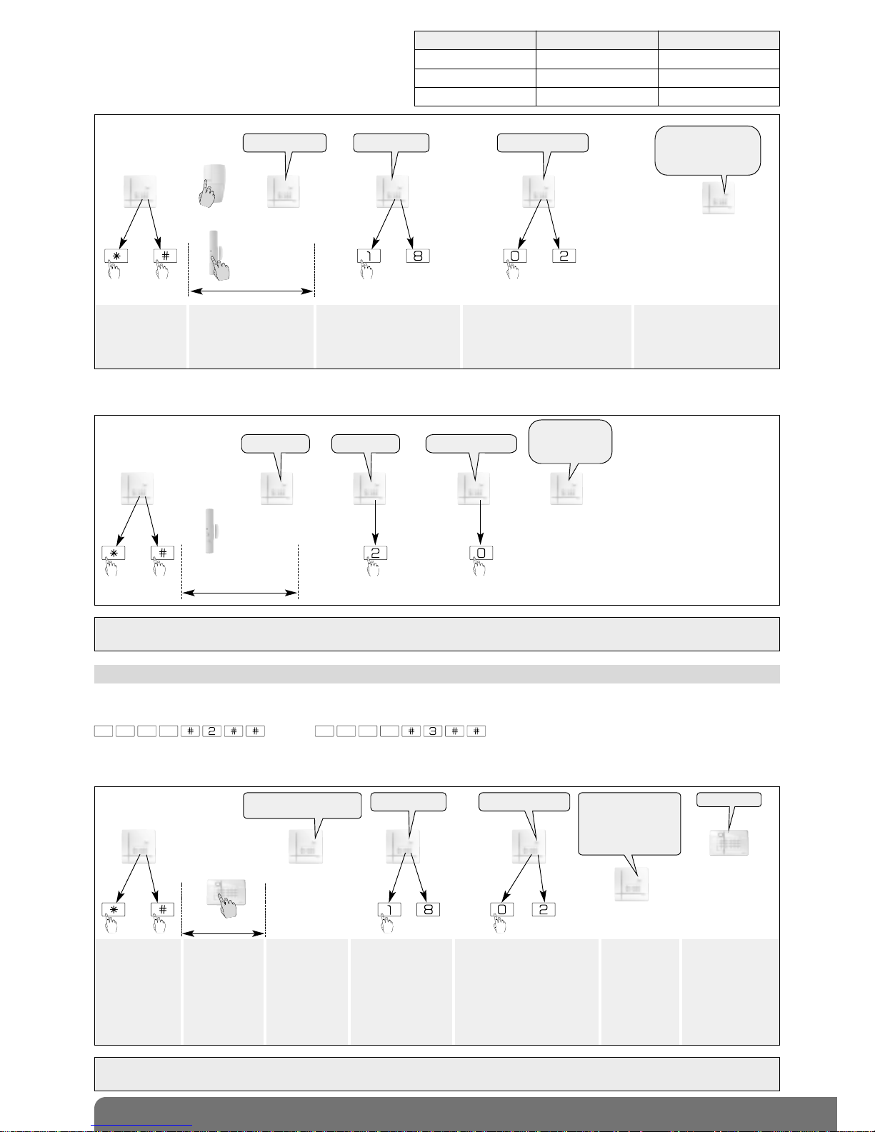
Example: programming 1st door/widow detector, allocated to group 2 and set for immediate triggering. The control panel
automatically allocates n° 1 to the first detector programmed.
“detector X” “group?” “time delay ?”
IMPORTANT: the control panel issues three short beeps to indicate a programming error. When this happens, perform
recognition programming again from the start.
then
Detector recognition programming involves selecting:
• a protection group from 1 to 8 (according to the type
of control panel),
• the type of triggering (immediate, time-delayed or
combined).
Press *then # on
the control panel
keypad
Press and hold the “test”
button until the control
panel responds
Select a group from 1 to 8*
(see table). Press the control
panel keypad to make the
selection.
Choose the type of triggering:
0: immediate • 1: time-delayed
2: combined
Press the control panel keypad to
make the selection
The control panel issues a
voice message to confirm
detector recognition
programming.
Control panel reference Number of groups Number of detectors
SH320AU 2 20
SH340AU 4 40
SH380AU 8 80
then to to
)
)
)
)
)
))
)
)
)
10 s max.
or
“detector X” “group?” “time delay ?”
“bip, detector X,
group Y, immediate
(or time-delayed
or combined)”
For recognition programming to work, the keypad must be in installation mode.
On power-up, the keypad is in user mode. To put it in installation mode, use the keypad to enter:
then
3.3 Programming the keypads to be recognised by the control panel
IMPORTANT: the control panel issues 3 short beeps to indicate a programming error. When this happens, perform recognition
programming again from the start.
• With a vocal keypad with tag reader SH640AX:
master code (factory: 0000) installer code (factory: 1111)
Press *then #
on the control
panel keypad
Press and hold
the “Off” button
until the control
panel responds
The control
panel issues a
voice message
to confirm
keypad
recognition
programming
The control panel
waits to know the
infrared detector
group (from 1 to 8
according to the
type of control
panel). Press the
control panel keypad
to select the group.
The control panel waits to
know the chosen triggering
type for the infrared detector:
0: immediate,
1: time-delayed,
2: combined.
Press the control panel
keypad to make the
selection
The control
panel issues a
voice message
to confirm
infrared
detector
recognition
programming
)
)
)
)
)
10 s max.
puis to to
“bip, remote control
unit X, bip, detector X”
“bip, remote control
unit X, bip,
detector X, group Y
(immediate, time-
delayed or combined)
“group?” “time delay?”
The keypad
issues a long
beep to
confirm
recognition
programming
“bip”
14
IMPORTANT: the control panel issues 3 short beeps to indicate a programming error. When this happens, perform recognition
programming again from the start.
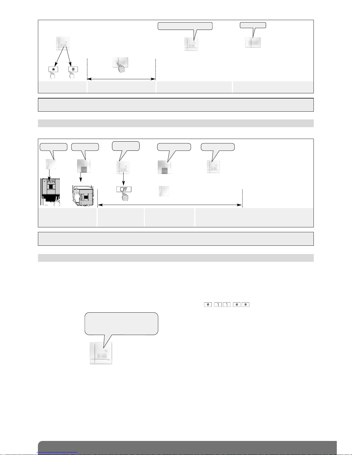
3.4 Programming a control panel with the siren
When powered, the siren is in installation mode
)))))
10 s max.
Briefly press the siren
“test” button.
Press and hold “Off”
until the control panel
responds
The siren issues an
audible signal to confirm
recognition programming
The control panel
specifies the siren n°
“bip, siren n°”“beeep”
“bip, Off,
control panel”
)))))
or
or
“bip” “bip”
• With an information and command keypad SH630AX:
IMPORTANT: the control panel issues 3 short beeps to indicate a programming error. When this happens, perform recognition
programming again from the start.
Press *then # on the
control panel keypad
Press and hold “Off” until the control
panel responds
The control panel issues a voice
message to confirm keypad recognition
The keypad issues a long beep to
confirm recognition programming
)
)
))
)
10 s max.
“beeep”
then
“bip, remote control unit X”
“bip, remote control unit 1,
bip, remote control unit 2,
bip, detector 1, group 2 immediate,
bip, siren 1”
3.5 Checking recognition programming
When checking programmed products, the control panel issues voice messages in the following order:
• remote control units,
• detectors,
• sirens,
• diallers,
• radio repeater relays or receivers.
To check all programmed products, use the control panel keypad to enter:
Example of check:

15
3.6 Deleting a programmed product
The control panel recognises 5 types of product according to their number.
To delete a programmed product, enter:
Example:
To delete the 2ndprogrammed siren, enter:
type of product product n°
3.7 Deleting all recognition programming
To delete all programmed products, enter:
press
and hold
“beeep”
IMPORTANT:
• If a radio repeater relay is deleted, all relayed products are not automatically deleted. Each product must be deleted from the
control panel.
- To delete a keypad, proceed as follows:
• put the system in installation mode using the KEYPAD to enter:
then
2. USING THE CONTROL PANEL, enter:
keypad n°
master code
installer code
Type of product Number
Detector 2
Remote control unit 3
Siren 4
Dialler 5
Radio repeater relay or receiver 7
 Loading...