

DAITEM SH271AX, SH272AX Installation Manual
(upgraded for e-Nova applications)
GB
100
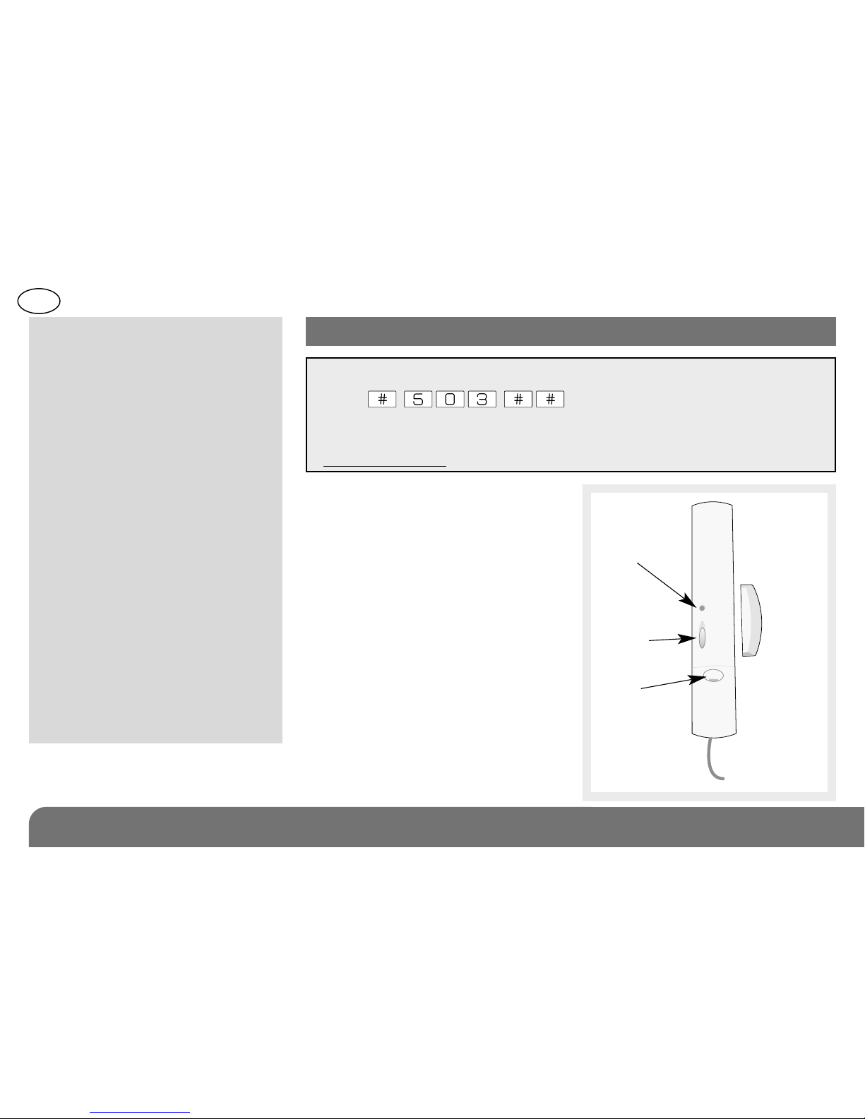
Built-in
magnetic
contact
External
contact(s)
LED
indicator
lamp
Test
button
Screw
cover
Contents
1. Introduction ........................... 100
2. Preparation ............................ 102
2.1 Opening ............................ 102
2.2 Power supply.................... 102
3. Programming......................... 103
4. Configuration......................... 104
5. Connection............................. 108
6. Installing................................. 109
6.1 Choosing the best place .. 109
6.2 Fixing method................... 109
6.3 Installing the magnet
holder ................................ 110
6.4 Connecting external
contacts............................ 112
7. Testing .................................... 114
8. Maintenance.......................... 116
8.1 Battery low indication....... 117
8.2 Changing the battery........ 117
9. Technical data ....................... 118
1. Introduction
The multicontact detector is used
to protect openings such as doors
& windows. It is fitted with:
• a built-in magnetic contact (reed
switch),
• a terminal block for connecting
external contacts such as:
- magnetic contacts (flush or
surface mounted, wide gap,
etc.),
- external roller shutter blind
sensors,
- piezo-electric glassbreak
sensors,
- shock sensors,
- pressure mats,
- other non-specific sensors.
IMPORTANT
• Some functions are only available with versions 2.0.0 or later
(press on the control panel keypad to check
the version).
• The operating differences with former ranges are described in the
compatibility booklet available in the Daitem installers section at
www.daitem.co.uk.

GB
101
Application example: a side door and garage
door protected by the same multicontact
detector.
The built-in magnetic contact
generates an intrusion alarm
The wide gap external magnetic
contact generates
an intrusion alarm
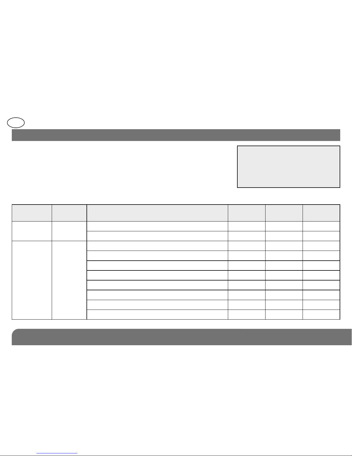
Choosing the external contact type
In the default configuration the type of contact chosen automatically pre-determines the level of alarm generated.
Nevertheless, it is possible to modify the alarm level for the built-in or external contact(s) (see § on Configuration).
Type of external contact Alarm level
Inactive (no contact connected) Normally closed contact (NC) Intrusion
Piezo-electric glassbreak sensor (NC) Intrusion
Roller shutter / blind sensor Intrusion
Normally closed contact Prealert
for roller shutter blinds
Shock sensor (NC)Prealert
Pressure mat (NO) Deterrence
Other external contacts (NC) Deterrence
NC: normally closed
NO: normally open
GB
102
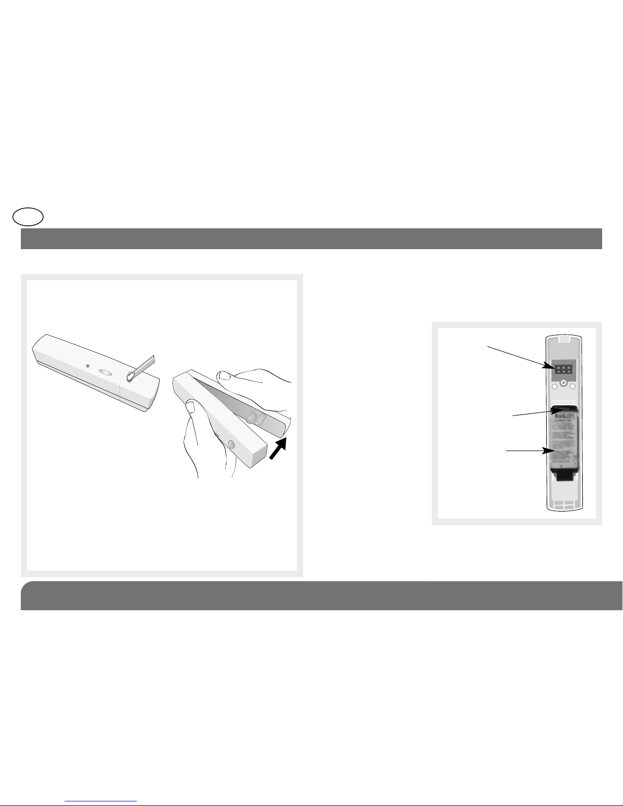
2.1 Opening
2. Preparation
1. Loosen the screws using a cross-head
screwdriver.
2. Unclip the base plate cover.
When switched on
the detector performs
a self-test. If the self-test is:
• correct, the LED indicator lamp lights up for 2 sec.,
• incorrect, the LED indicator lamp flashes every 5 sec.
Guarantee sticker:
Remove the pre-cut part of the sticker and stick it
to the guarantee certificate in the user manual
supplied with the control panel. If you are adding
the siren to an existing system, use the guarantee
sticker provided with this product.
2.2 Power supply
The lithium battery pack is clipped into position (see
diagram below). An arrow indicates which way to
connect it.
Connection
terminals
for external
contacts
Alignment arrow
Lithium battery
GB
103
3. Programming
During recognition program-ming, the
product to be programmed for use
with the control panel does not need
to be placed next to it. In fact, we
recommend you place the product at a
short distance from the control panel
(at least 2 meters away).
Programming enables multicontact
detectors to be recognised by the
control panel.
1. To programme multicontact
detectors the control panel
must be in installation mode. If
it is not, you will require the user’s
master code, press:
then press:
master code
engineer installer code
2. Programme the device as follows
The control panel indicates an error
by emitting 3 short beeps.
When this happens programming
should be carried out again.
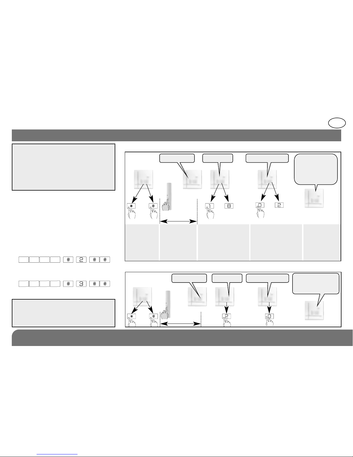
10 s max.
Press ‹then
# on the
control panel
keypad
Press and hold
the “test”
button until the
control panel
responds
The control panel waits
for a group to be chosen
(from 1 to 8)*. Choose
the groups by pressing
the corresponding
numeral on the control
panel keypad
The control
panel gives a
voice message
to confirm
detector
programming
)
)
)
)
)
then
to
“detector X” “group ?” “time delay?”
“beep, detector X,
group Y
immediate
(or delayed
or combined)”
to
* according to the
type of control panel
*
Choose the type
of triggering:
0: immediate,
1: delayed,
2: combined. Use the
control panel keypad
to select the type
Example: programming of 1st detector allocated to Group 2 with immediate triggering.
10 s max.
then
“detector 1” “group ?” “time delay?”
“beep, detector 1
group 2,
immediate”
)
)
)
)
)
GB
104
4. Configuration
IMPORTANT
• The cover must be open when
configuring the detector.
• An unused built-in or external
contact must be configured as
inactive.
Configuring the multicontact detector enables the characteristics of the 2
contacts (built-in and external) to be defined.
To configure the contacts:
• choose the Parameter number corresponding to the Contact Type to be
configured,
• choose the Parameter Value corresponding to the characteristics of the
contact to be configured.
Type
of contact
Parameter
n°
Contact characteristics
Parameter
vaue
Supervised
opening
Alarm
level
Built-in 1
inactive 1 no active (NC) (factory setting) 2 yes intrusion
External 3
inactive (factory setting) 1 no normally closed contact (NC) 2 yes intrusion
roller shutter blind sensor 3 no intrusion
normally closed contact for roller shutter blinds 5 no prealert
piezo-electric glassbreak sensor (NC) 6 no intrusion
shock sensor (NC) 7 no prealert
pressure mat (NO) 8 no deterrence
other external contacts (NC) 9 no deterrence

GB
105
• Follow the configuration sequence described below:
LED indicator
lamp not lit
LED indicator
lamp lit
about
5 sec.
about 10 sec. about 2 sec.about 10 sec.
To start the
sequence press &
hold the button until
the LED indicator
lamp goes out
Press as many times
as the required
Parameter number
Press & hold
until the LED
indicator lamp
briefly goes out
Press as many times
as the required
Parameter Value
To end
the sequence
press & hold until
the LED indicator
lamp goes out
LED Indicator
lamp lit =
correct
configuration
Start Press 3 times to select
the external contact
Press once
to accept
selection
Press 2 times to select
the NC contact
End
Configuration example: configuring the multicontact detector with an external contact (Parameter n° 3) connected
to a wide gap normally closed contact (Value 2). An intrusion alarm is generated when the garage door is opened.
3 2
Sequence
 Loading...