

DAITEM SH148AX Installation Manual


GB
16
The outdoor anti-masking detector has been specially designed to
detect intruders before they break in and is able to tell the difference
between a human being and an animal.
Its anti-masking function allows it to detect attempts to mask
detection.
The detector has 2 detection beams (upper and lower), both of which
must be broken simultaneously for the alarm to be triggered. The
detection process prevents the device from triggering false alarms
due to the sun or the headlights of a car.
Furthermore, a temperature compensation system automatically
increases and backs up detection sensitivity.
Its compact size, narrow horizontal protection, smaller detection
range and anti-masking function make it an ideal device for
protecting façades, balconies, various types of windows and any
other access points.
Contents
1. Introduction ........................................................................................... 16
2. Preparation ............................................................................................ 17
2.1 Opening the detector........................................................................ 17
2.2 Description ........................................................................................ 17
2.3 Power supply .................................................................................... 18
3. Recognition programming................................................................... 19
4. Parameter-setting ................................................................................. 20
5. Installation precautions........................................................................ 21
6. Installing the detector .......................................................................... 22
6.1 Testing the radio link......................................................................... 22
6.2 Fixing the detector in place .............................................................. 22
7. Detection settings and configuration................................................. 23
7.1 Detection range................................................................................. 23
7.2 Adjusting the detection angle horizontally....................................... 25
7.3 Setting the operating options ........................................................... 25
7.4 Anti-masking function....................................................................... 26
8. Testing operation .................................................................................. 27
8.1 Testing the detection zone................................................................ 27
8.2 Performing a real test........................................................................ 27
9. Maintenance .......................................................................................... 28
9.1 Fault indications................................................................................ 28
9.2 Changing the batter.......................................................................... 28
10. Technical data ..................................................................................... 29
1. Introduction
Recommendations
The user must not attempt to access the detector’s internal parts, except areas described in this manual. If the user does access these parts,
the product guarantee will be considered null and void and DAITEM shall not be held responsible for any problems. Touching the detector’s
internal parts and/or electronic components can damage the product. Furthermore, the detector is designed in such a way that these parts
and components do not need to be accessed for operation or maintenance purposes.
IMPORTANT
• Some functions are only available with control panel version 2.0.0 or
later (enter ) on the control panel keypad
to check the version).
• Operating differences with respect to former ranges are described in
the compatibility booklet available in the Daitem Installers section at
www.daitem.co.uk.
GB
17
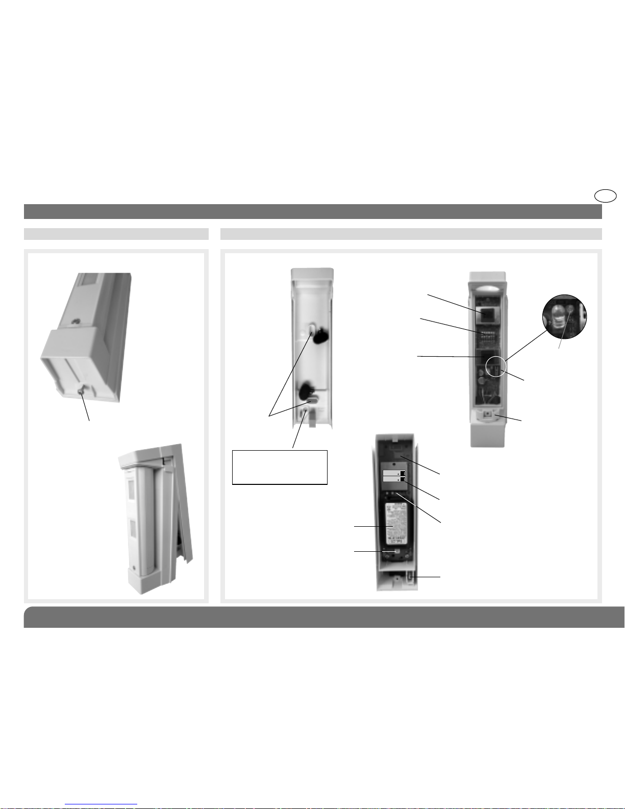
Remove the base.
2. Preparation
2.1 Opening the detector 2.2 Description
N.B. The product is delivered unscrewed.
d
Fixing
at 2 points
(screws not
supplied)
Base
Radio box
Radio card
Guarantee sticker
Test button
Programming LED
Lithium battery
Tamper tab
Detection module
Upper detection
beam
Lower detection
beam
LED indicator
Tamper tab
Locking mechanism
Dip switches
for operating
options
SH148AX
A1142A047879
Coller sur certif
SH148AX
A1142A047879
Coller sur certif
1 screw to be positioned on
the snap-off part to ensure
protection against removal
(screw not supplied).
GB
18
IMPORTANT: when powered, the LED
indicator positioned behind the lower
lens flashes quickly for several
seconds before going out (detection
circuit stabilisation period).
1. Connect the lithium power pack referring
to the arrow to make sure it is the right way
round.
When powered, the detector performs
a self-test.
If the self-test is satisfactory, the programming
indicator lights up for roughly 2 s.
2. Guarantee sticker
Remove the pre-cut part of the sticker and stick it to the guarantee certificate in the
user manual supplied with the control panel. If you are adding to an existing system,
use the guarantee certificate supplied with this product.
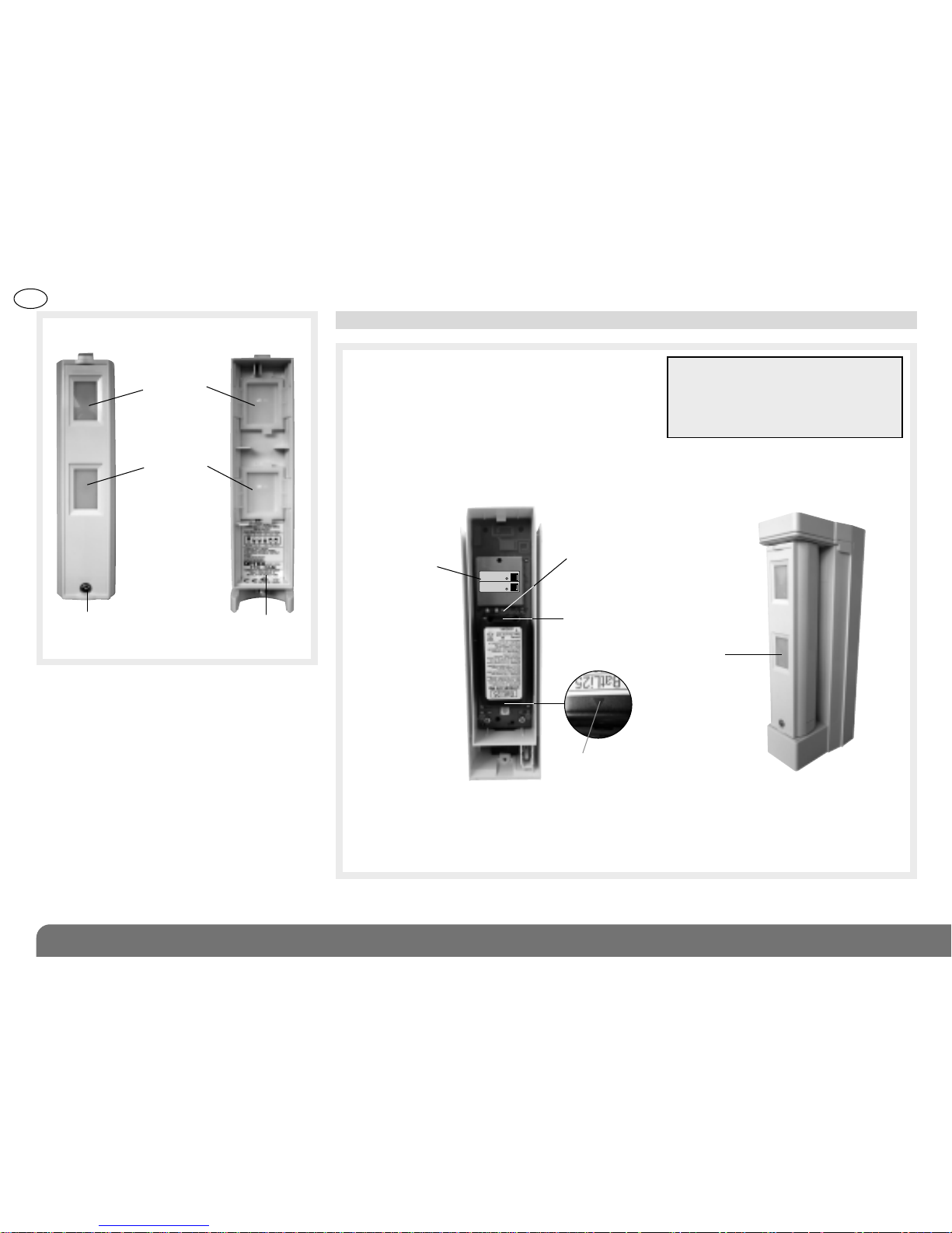
2.3 Power supply
Inside view of radio box Front panel
LED indicator
Unlocking tab
Programming LED
Guarantee
sticker
Upper lens
Lower lens
Front panel
(head-on view)
Front panel
(inside view)
Closing
screw
Sticker listing
operating
options
Directional arrow
SH148AX
A1142A047879
Coller sur certif
SH148AX
A1142A047879
Coller sur certif
GB
19
3. Recognition programming
IMPORTANT
• The device does not need to be placed close to the control panel for recognition programming. In fact, we advise you to move the
product at least 2 metres away from the control panel.
• The detector n° is allocated automatically by the control panel during recognition programming.
This operation allows the control panel to recognise the detector.
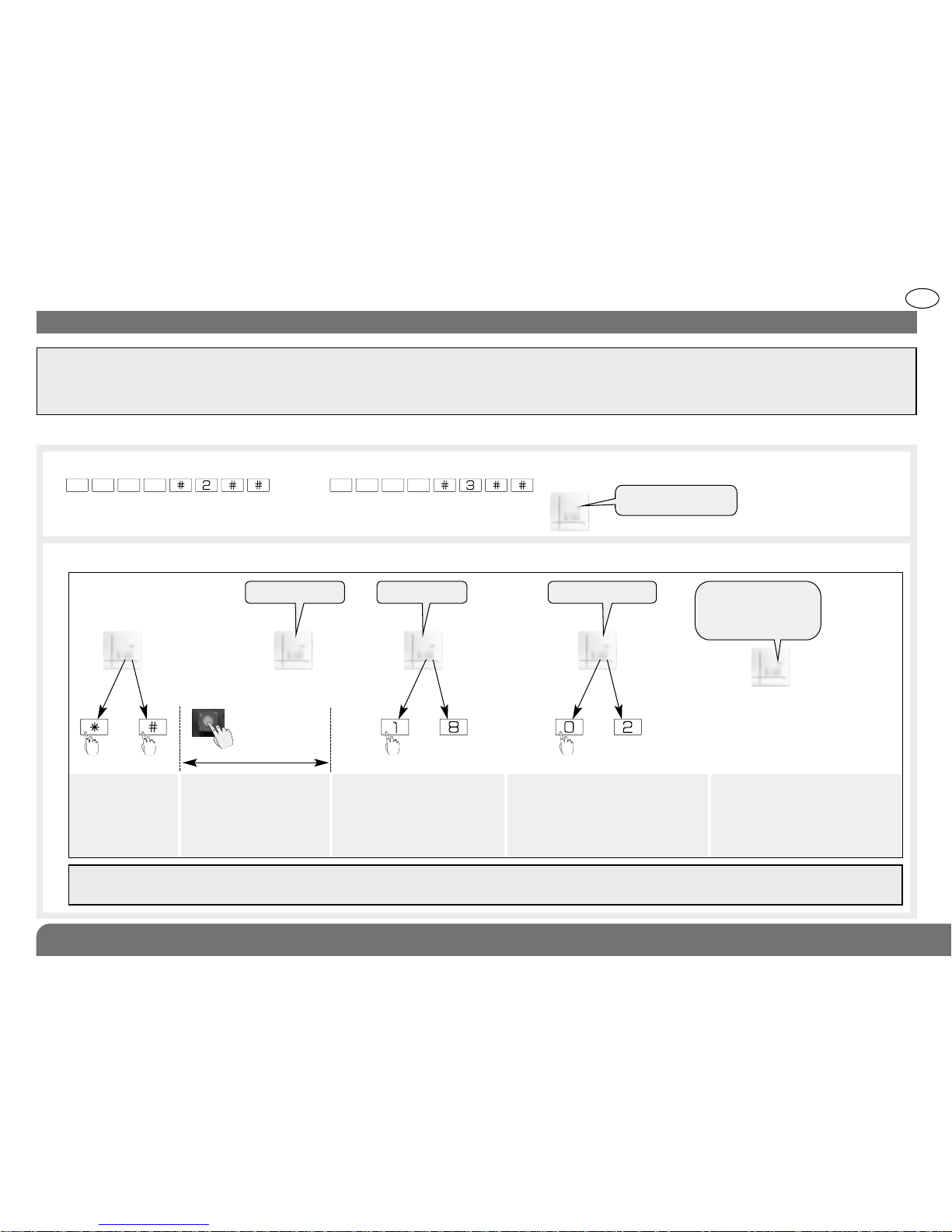
2. Proceed as follows for recognition programming:
1. For detector recognition programming, the control panel must be in installation mode. If it is not, ask the user to enter:
then
IMPORTANT: the control panel issues three short beeps to indicate a programming error. When this happens, programming must
be performed again from the beginning.
Press *then # on
the control panel
keypad.
Press and hold the “test”
button until the control
panel responds.
Select the group from 1 to
8*. Use the control panel
keypad to do this.
Select the time delay:
0: immediate
1: delayed
2: combined
Use the control panel
keypad to do this.
The control panel
issues a voice
message to confirm
detector recognition
programming.
then to
)
)
)
)
)
10 s max.
“detector X” “group ?” “time delay?”
*
to
* depending on the
type of control panel
master code (factory: 0000) installer code (factory: 1111)
“beep, detector X,
group Y, immediate
(or delayed
or combined)”
“beep, installation
mode”
GB
20
The motion detector is factory-configured
for deterrence (see your control panel
installation guide for system responses).
The alarm level can be changed by resetting
the parameters as shown opposite.
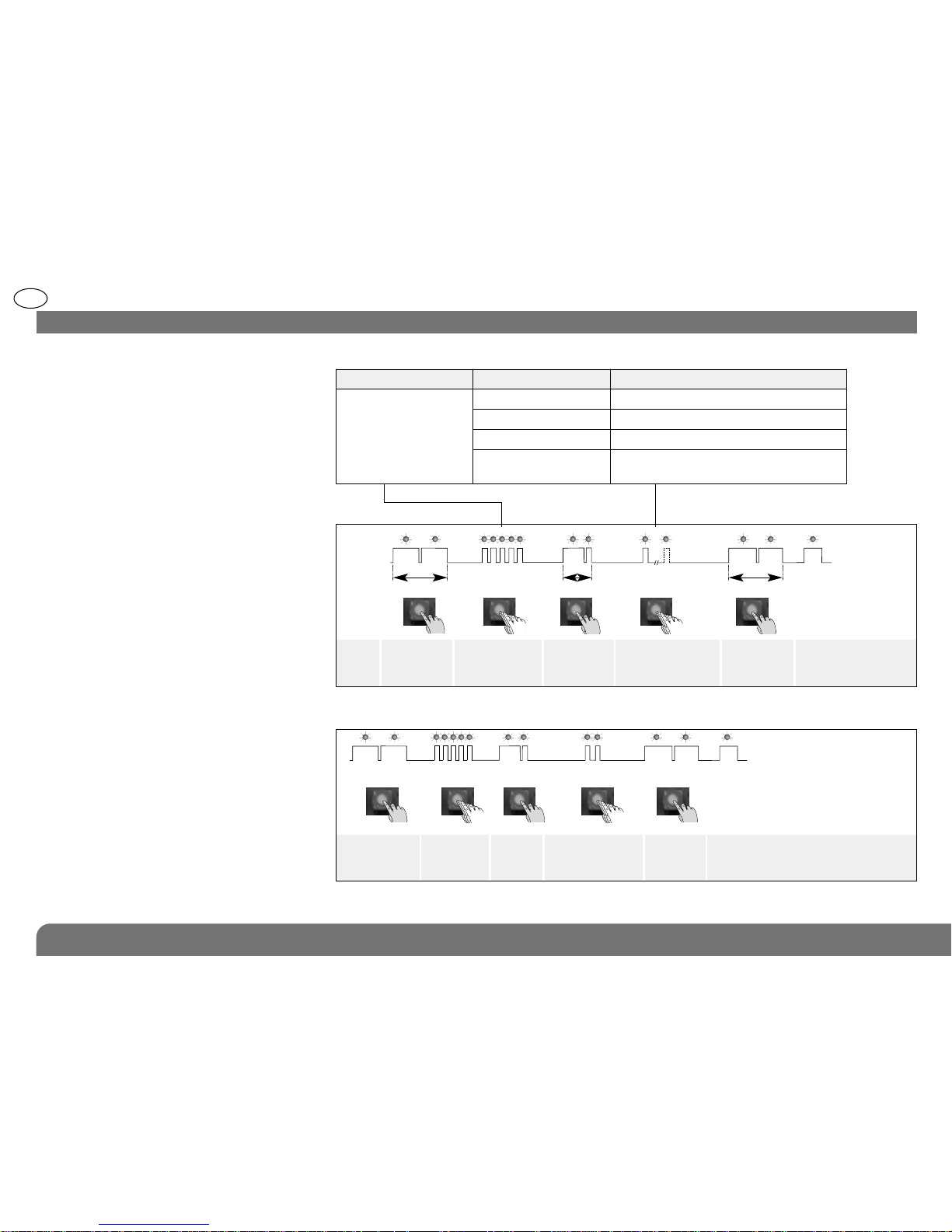
Parameter-setting sequence
Programming
LED off
Programming
LED on
Programming
sequence
about
5 s.
about 10 s.
about 2 s.
about 10 s.
To start,
press and
hold until the
LED goes out.
Press the button
5 times for the
parameter
number
Press and
hold until the
LED briefly
goes out
Press the button
1 to 4 times for the
parameter value
To end, press
and hold the
button until the
LED goes out
Programming
LED steadily lit
= parameter
set correctly
Start
Press the
button 5 times
to select the
alarm level
Press
once to
create a
space
Press the button
twice to select the
prealarm level.
End
Parameter-setting example: setting the
detector to prealarm level: parameter
number 5, parameter value 2.
5 2
about 2 s.
tt
4. Parameter-setting
{
{
Parameter N° Alarm level Parameter value
5
Intrusion 1
Prealarm 2
Deterrence 3 (factory setting)
Warning
4 (function compatible with control panel
versions 2.0.0 and later)
 Loading...