

DAITEM SH146AX Installation Manual

Updated for e-Nova applications

GB
72
Contents
1. Introduction .................... 72
2. Preparation..................... 73
2.1 Opening
the detector................ 73
2.2 Description................. 73
2.3 Power supply............. 74
3. Recognition
programming.................. 75
4. Parameter-setting.......... 76
5. Installation
precautions..................... 77
6. Installing the detector ... 77
6.1 Fixing the detector
in place....................... 78
6.2 Setting the
detection range.......... 80
6.3 Setting the vertical
angle........................... 81
7. Operating options.......... 82
8. Testing operation ........... 83
8.1 Testing the
detection zone........... 83
8.2 Performing
a real test.................... 83
9. Maintenance................... 84
9.1 Fault indications......... 84
9.2 Changing
the battery.................. 84
10. Technical data.............. 85
1. Introduction
The detector comprises a mechanical device for adjusting the
detection zone. The protected area can be checked with the
help of a LED located behind the lens.
9 m
3 m
5,5 m
3 m
8 m
12 m
0
8 m
Top view
Side view
Adhesive masking strips (supplied)
The 12 m external motion detector with
anti-mask feature detects intruders
before they break in. Fitted with a
specific lens and two infrared sensors,
the detector can tell the difference
between a human being and a small
animal. Combined with internal
electronics, the anti-mask feature
detects attempts to mask the detector.
Its detection angle can be adjusted by
adding masking strips to the lens. The
detector’s sensitivity can be set to
reduce the likelihood of false alarms
triggered by movement (cars, persons or
animals outside of the required detection
zone). The ideal installation height is
between 2.5 and 3 m as this makes it
difficult for intruders to access the
detector.
IMPORTANT
• Some functions are only available with control panel version 2.0.0 or later (enter )
on the control panel keypad to check the version).
• Operating differences with respect to former ranges are described in the compatibility booklet available
in the Daitem Installers section at www.daitem.co.uk.
GB
73
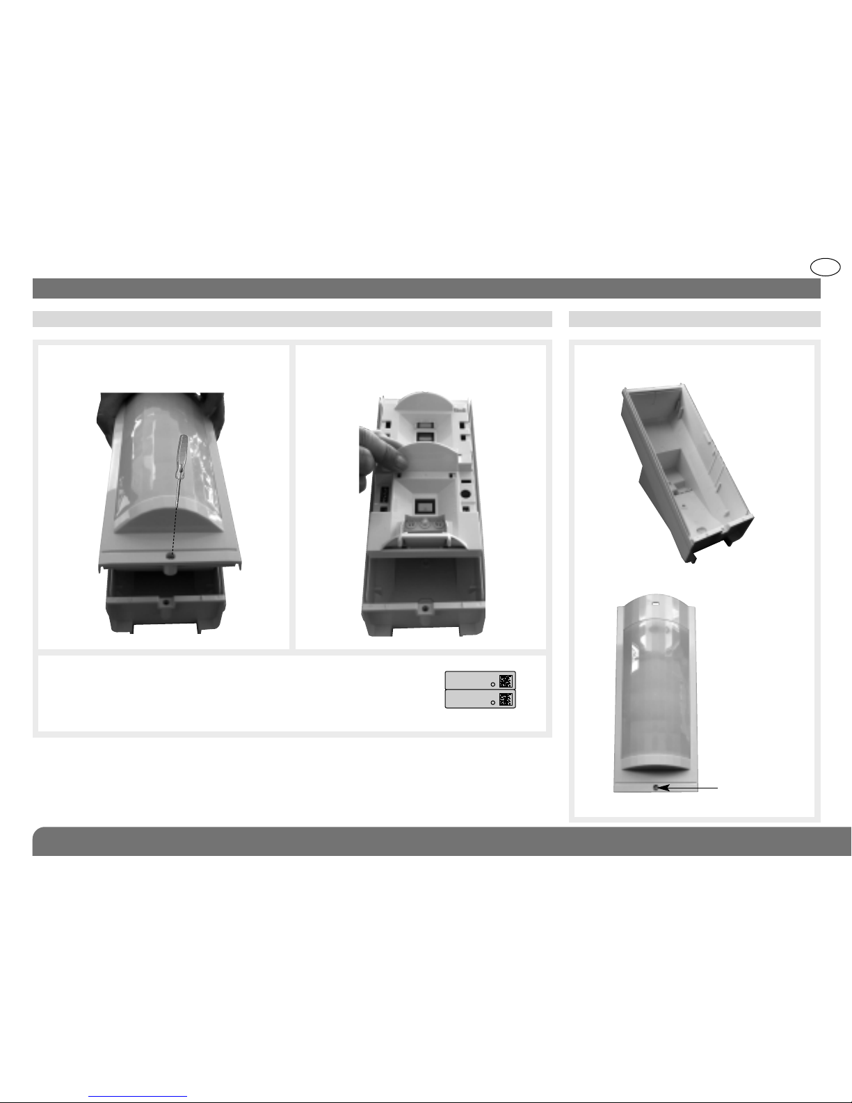
2. Preparation
2.1 Opening the detector 2.2 Description
Back box
Locking screw
Cover
d
d
1. Loosen the locking screw using a Philips
screwdriver and remove the cover.
3. Guarantee sticker: remove the pre-cut part of the sticker and
stick it to the guarantee certificate in the user manual supplied
with the control panel. If you are adding to an existing system,
use the guarantee certificate supplied with this product.
2. Remove the back box.
.
SH146AX
A1142A047879
Coller sur certif
SH146AX
A1142A047879
Coller sur certif
GB
74
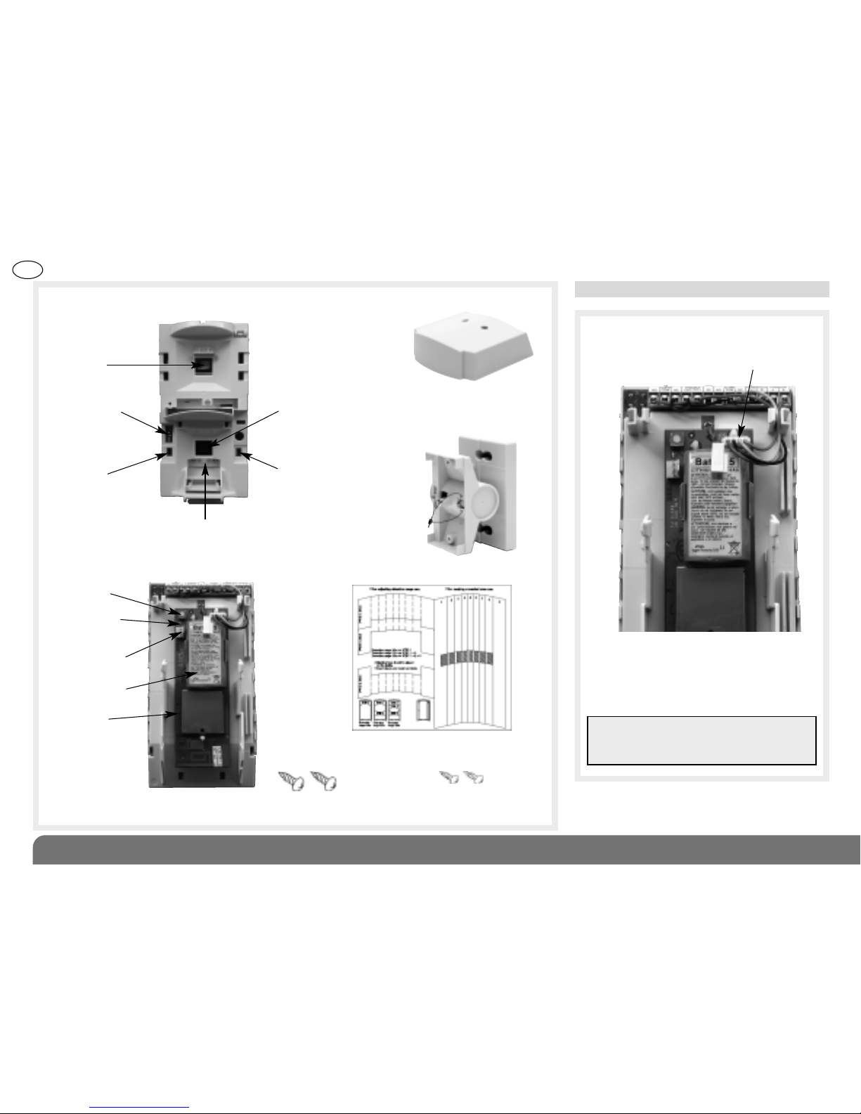
Set of upper
detection
beams
Set of lower
detection beams
Anti-mask
selection dip
switch
Operating option
dip switches
Sensitivity
selection dip
switch
LED
Two 3 x 10 mm screws
(for fixing cover)
Two 4 x 20 mm screws (for
fixing box to adjustment bracket)
Test button
Lithium battery
connector
Programming
LED
Lithium battery
Radio card
Detection module
(front view)
Detection module
(rear view)
Angle adjustment
bracket
Cover
Sheet of adhesive masking strips
Bag of accessories
When the detector is switched on, the
LED flashes every second for 45 s
(detection circuit stabilisation period).
The programming LED lights up for 2 s.
Connecting the battery.
2.3 Power supply
d
Detection circuit
connector
IMPORTANT: if the LED does not flash,
check the connector is in the right
position (detection circuit).

GB
75
2. Proceed as follows to programme the detector to be recognised by the control panel.
IMPORTANT: the device does not need to be
placed close to the control panel for
recognition programming. In fact, we advise
you to move the product at least 2 metres
away from the control panel.
3. Recognition programming
1. Put the control panel in installation mode
by entering the following:
then:
master code
installer code
*
IMPORTANT: the control panel indicates there is an error by emitting 3 short beeps.
When this happens programming should be carried out again.
10 s max.
Press and hold the
“test” button until
the control panel
responds
The control panel
waits for a group
to be chosen (from
1 to 8)*. Choose
the groups by
pressing the
corresponding
numeral on the
control panel keypad
Select the time delay:
0: immediate
1: delayed
2: combined
Use the control panel
keypad to do this.
The control panel
gives a voice
message to
confirm
Press *then #
on the control
panel keypad
* Depends on the type of the control panel
then to to
“group?”
“time delay?”“detector X”
“beep, detector X,
group Y, immediate
(or delayed
or combined)”
))
))
)
GB
76
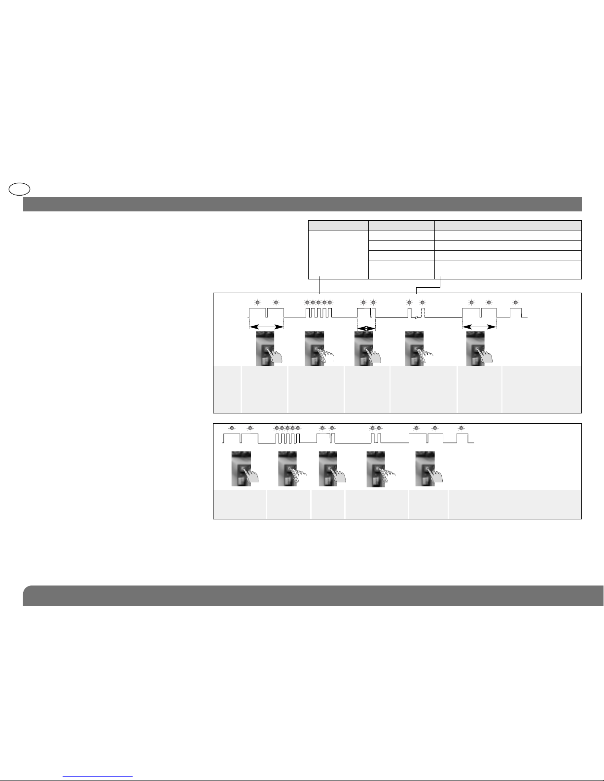
The motion detector is factoryconfigured for a deterrence (see
your control panel installation
guide for system responses). The
alarm level can be changed by
resetting the parameters as
shown opposite.
Parameter-setting
sequence
Programming
LED off
Programming
LED on
Programming
sequence
about
5 s.
about 10 s.
about 2 s.about 10 s.
Press the
button 5 times
for the
parameter
number
Press and
hold until the
LED briefly
goes out
Press the button
1 to 4 times
for the parameter
value
To end,
press and
hold the
button until
the LED goes
out
Programming LED
permanently on =
parameter set
correctly
{
{
Start Press the
button 5 times
to select the
alarm level
Press
once
to create
a space
Press the button
twice to select the
prealarm
End
Parameter-setting example:
setting the detector to full ) prealarm :
parameter number 5, parameter value 2.
5 2
about 2 s.
tt
4. Parameter-setting
To start,
press and
hold until the
LED goes out
Test
button
Parameter n° Alarm level Parameter value
5 Intrusion 1
Prealarm 2
Deterrence 3 (factory setting)
Warning 4 (the feature is available using control panels
with 2.0.0 version software or later)
 Loading...