

DAITEM SH101AX, SH103AX, SH102AX, SH100AX Installation Manual
Upgraded for e-Nova applications

212
GB
Contents
Foreword............................................................................... 213
1. Presentation..................................................................... 214
1.1 Function........................................................................ 215
1.2 Description ................................................................... 217
1.3 Accessories.................................................................. 218
2. Preparation....................................................................... 218
2.1 Opening back-box ....................................................... 218
2.2 Opening cover.............................................................. 219
2.3 Guarantee label............................................................ 219
3. Preparation of the wireless transmitters & receivers
(SH102AX or SH103AX)................................................... 220
3.1 Power supply................................................................ 220
3.2 Programming the wireless modules............................ 221
3.3 Voice identification message recording....................... 222
3.4 Wireless receiver alarm level parameter setting.......... 223
3.5 Arming with a beam blocked (in alarm)
or an anomaly............................................................... 224
4. Infra red barrier installation............................................ 225
4.1 Choice of module positioning for various types
of protection ................................................................. 225
4.2 Installation precautions ................................................ 226
4.3 Testing radio connections (SH102AX & SH103AX)..... 227
4.4 Fixing the base............................................................. 227
4.5 Interconnecting multiple non radio beam sets............ 230
5. Configuration and adjustments of infra-red detection.. 236
5.1 Description ................................................................... 236
5.2 Selection of infra red beam transmit
& receive channels ....................................................... 237
5.3 Selection of Normally Closed/Normally Open ............ 239
5.4 Optical alignment & verification................................... 239
5.5 Adjustment of detection speed ................................... 242
5.6 Adjustment of alarm inhibit period............................... 242
6. Functional installation test ............................................. 243
6.1 Status of LED indicators.............................................. 243
6.2 Detection test .............................................................. 243
6.3 Radio connection test.................................................. 244
7. Live tests........................................................................... 245
8. Maintenance..................................................................... 246
8.1 Indication of anomalies and faults............................... 246
8.2 Changing the batteries................................................. 247
9. Summary of adjustment of the microswitches ........... 249
10. Installation sheet ........................................................... 250
11. Technical specification ................................................. 251
Recommendations
The user must not attempt to access the device’s internal parts, except areas described in this manual. If the user does access these
parts, the product guarantee will be considered null and void and DAITEM shall not be held responsible for any problems. Touching
the device’s internal parts and/or electronic components can damage the product. Furthermore, the device is designed in such a way
that these parts and components do not need to be accessed for operation or maintenance purposes.
213
GB
Thank you for purchasing our infra red barrier beam.
In order to carry out the installation under the best conditions, we strongly advise:
1. first reading chapter “1. Presentation”,
2. carefully selecting the siting of the various modules and the “type of protection” described in this Installation Manual,
3. strictly follow the chronological order of the successive procedures,
4. create a drawing of the site with a key indicating the position of the IR beams and the radio transmissters, and place a
copy with the Installation file for future maintenance reference.
Foreword
NOTE: the terms & conditions of sale are printed on our invoices, and separate copies and copies of the warranty are available
upon request.
Treatment of electrical appliances and electronic equipment at the end of product’s lifetime (Applicable in the European Union and other European
countries operating a system of collection. This symbol, on the product or its packing, indicates that this product should not be treated with domestic
waste. It must be given to a suitable collection point for the recycling of the electric and electronic components. By you ensuring that this product is correctly disposed of, this will help to prevent the negative consequences for the environment and human health. For all additional information about the recycling
of this product, contact the local community recycling centre, or the company from whom you purchased the product.
The installer recommends and carries out the installations under his only responsibility. It is his responsibility to conform to the
regulations in force, and to carry out the instructions and recommendations contained in this Installation & Instruction manual.
Possible dysfunctions of the system caused by not respecting these recommendations are the single responsibility for the installer.
Precautions:
• Do not to use this product for a use other than detection of movement such as people or vehicles.
• Do not use the product to actuate a powered roller shutter, etc, that could cause an accident.
• Do not to touch the terminals of the product with the wet hands (do not to touch the product if it wet by the rain, etc). There is a risk
of electric shock.
• Never try to disassemble or repair the product. This could cause a fire or damage the device.
• Do not to use batteries other than those specified.
• Do not mix used and unused batteries with different levels of charge. Failure to respect this precaution could cause an explosion, an
escape of electrolyte, a pollutant gas emission with potentially harmful consequences for personnel and product.
• Always take care handling any batteries as there can be serious burn, explosion,or fire hazard. Do not attempt to recharge, apply a
short circuit across their terminals, crush, or disassemble, heat to more than 100C (212F), incinerate or expose to water.
• Do not to pour water on the product from a bucket, or a pipe, etc, this could penetrate into the product and damage the
components.
• To ensure continued secure performance, clean and check the device periodically. If you encounter a problem, have the product
repaired or exchanged by qualified personnel.

214
GB
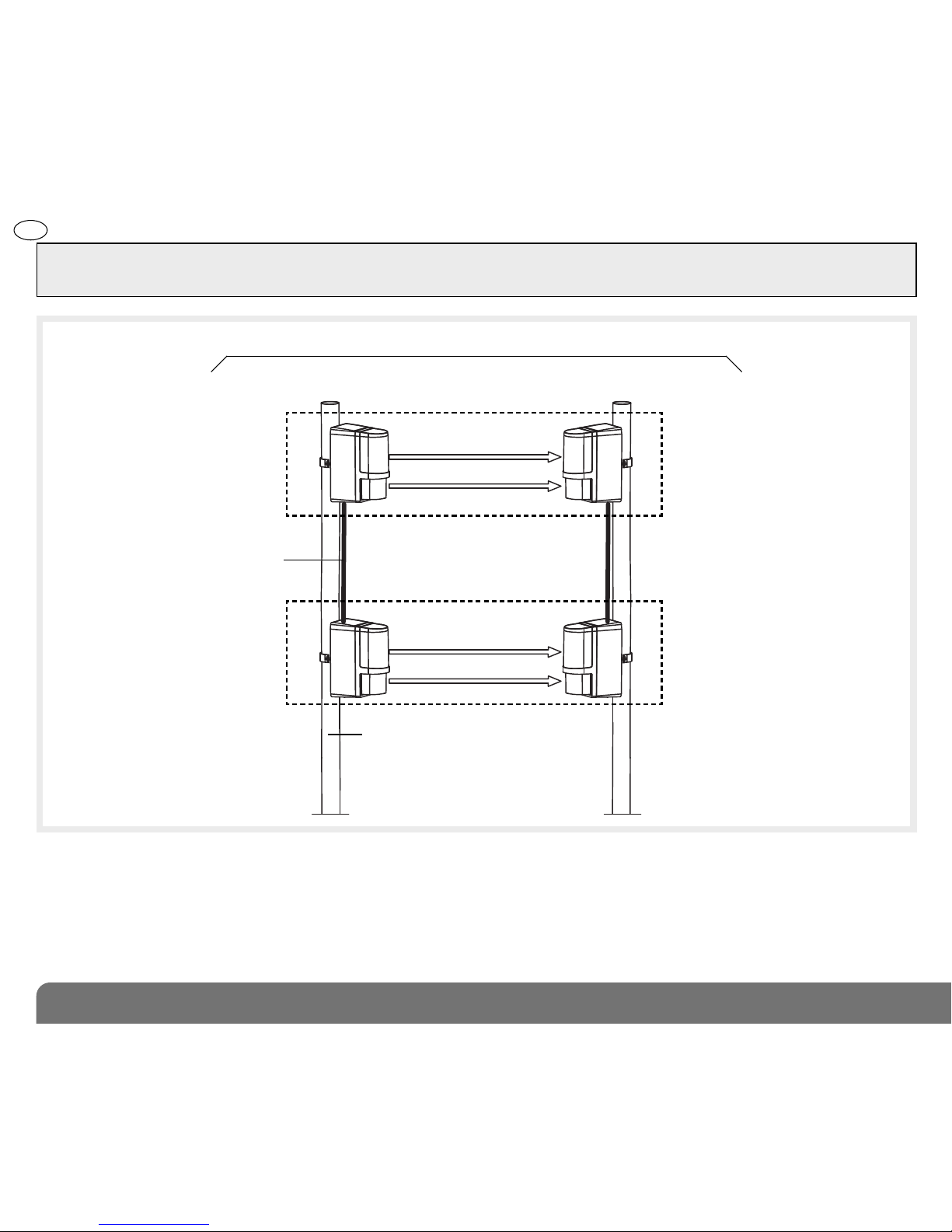
1. Presentation
Example of an infra-red barrier
installed outside to protect
a passageway.
TRANSMITTER
column
RECEIVER
column
IMPORTANT
• Some functions are only available
with versions 2.0.0 or later
(press
on the control panel keypad to
check the version).
• The operating differences with
former ranges are described in the
compatibility booklet available in
the Daitem installers section at
www.daitem.co.uk.
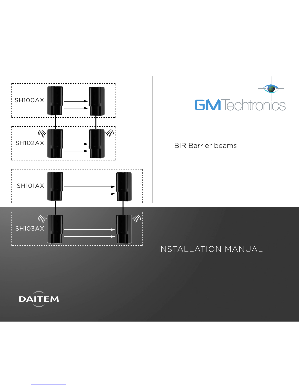
This manual describes the installation of the following products:
• SH100AX: infra red barrier, 2 beam 30 m without radio.
• SH101AX: infra red barrier, 2 beam 60 m without radio.
• SH102AX: infra red barrier, 2 beam 30 m with radio.
• SH103AX: infra red barrier, 2 beam 60 m with radio.
• Detection Barriers SH100AX, SH102AX, SH101AX and SH103AX are barriers with active
infra-red beams intended to provide perimeter or trap detection around the exterior of the
protected premises (they will also detect the presence of animals, depending upon their
size and the mounting height of the barrier beams. By selecting the appropriate mounting
height, small animals can be ignored while intruders are still detected.
• Each barrier comprises an infra red transmitter and receiver, each powered by a lithium
power pack (supplied). The battery life of both the 30 m and 60 m units is 5 years.

215
GB
1.1 Function
• Wireless Infra-red barriers SH102AX and SH103AX are compatible with TwinBand®(400/800 MHz) (see following diagram), and
allow the transmission of alarms and faults to a Daitem Espace alarm control panel.
• Chaining/Stacking Function: infra-red barriers without radio, models SH100AX or SH101AX can be connected to the radio infra-red
barriers models SH102AX or SH103AX by cable, making it possible to add additional and/or stacked detection beams
• Barrier beam protection can thus be made up, of one or more “Receiving infra-red beams” on one side and one or more
“Transmitting infra-red beams” on other side.
• The infra-red barrier signals detection when one or several pairs of infra-red beams is interrupted. This break in a beam pair initiates
the sending of a radio message by the infra red receiver radio transmitter to the Espace control panel (indicating the level of
alarm: warning, deterrence, prealert and intrusion).
• The barrier beam has a function “environmental disqualification” which permits inhibition of alarm signals in case of unfavourable
environmental conditions such as snow, fog, heavy rain, ice etc. all of which are potential causes of false activations... in such
cases alarms will be inhibited until the adverse conditions are finished.
NOTE: Factory default is with Environmental inhibit enabled.
• The barrier also indicates:
- low batteries,
- radio faults,
- tamper protection (mechanical and cutting of connecting cables),
- masking or faulty alignment (resulting in an open/broken beam detection).
In the case, of a stacked or chained installation, information (alarm, low batteries, tamper detection…) are transmitted from a Slave
unit (without radio) via the main module (with radio) by the wired interconnection.
• Each module has:
- 2 tamper switches, one to detect the opening of the module, the other as a back tamper to detect removal from its mounting position
- 1 infra-red ray transmission/réception channel selector for the applications of stacking or chaining for long distance,
• Each infra-red receiver has:
- 2 micro-switches for adjusting detection speed,
- 1 “Alarms” indicator LED for assistance with adjustment of alignment and carrying out detection testing,
- 1 jack for controlling optical alignment.
• Each infra-red module can be installed on a wall or a post.
216
GB
Slave module:
Infra red receiver
without radio
Master module: Infra red
receiver with radio transmitter
The radio allows the transmission
to the control panel of the status
of the infra red receiver column of;
Intrusion or beam blocked and the
status of the receiver column:
• low battery
• anti-tamper (cover or back tamper,
or connecting cable cut)
• radio fault
INFRA RED BEAM BARRIER
TRANSMITTER
column
RECEIVER
column
Slave module:
Infra red transmitter
without radio
SH100AX or SH101AX
SH102AX or SH103AX
Radio transmission to control panel
)))))
(((((
Round multi-core cable, approx 5 mm
dia., 4-wire telephone type each
approx 0.22 sq mm. Max length
approx 100 m for extended range
applications
Master module: Infra red
transmitter with radio transmitter
The radio allows the transmission
to the control panel of the status
of the Infra red transmitter
column:
• low battery
• cut cable
• radio fault
Each post can be made up of:
a ground plate, MJM31X, with a post
height of 60 cm (diameter 40 mm),
and built up with 50 cm pole extensions
MJM28X (40 mm dia.)
Radio transmission to control panel
1 dual infra red beam
IMPORTANT: the infrared barrier only has the “OR” detection function. This means that for a stacked installation (when modules are
superimposed), movement is detected as soon as one or several infra red beams are broken. The barrier does not include the “AND”
function (which only detects movement when all the beams are interrupted).
217
GB
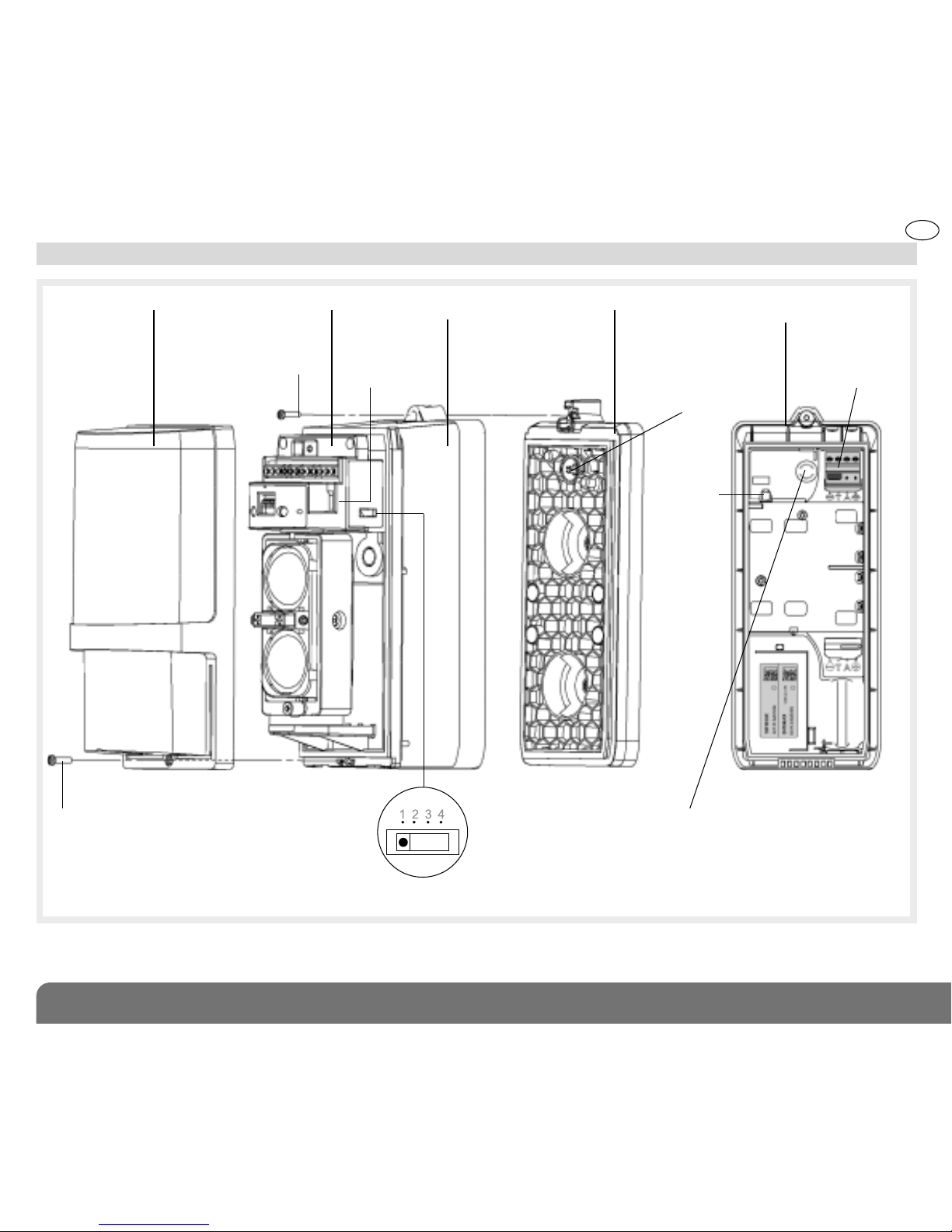
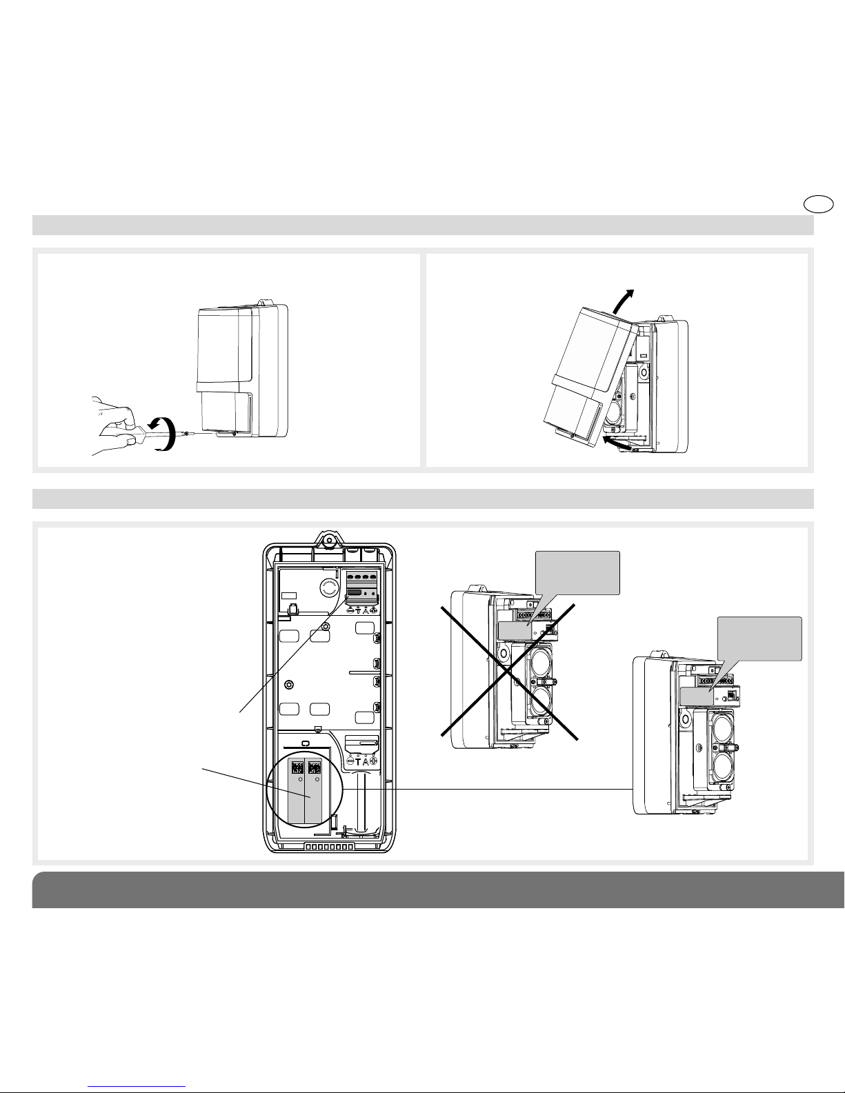
1.2 Description
Detection module
Cover
Hood
anti-tamper
switch
Back box
external view
Mounting base
infra red transmission channel selector
Front cover fixing screw
Back box
fixing screw
Back box
anti tamper
actuation pin
Radio module
connector block
Push
button
Back box
internal view
Back box anti tamper,
opening and forcing
218
GB
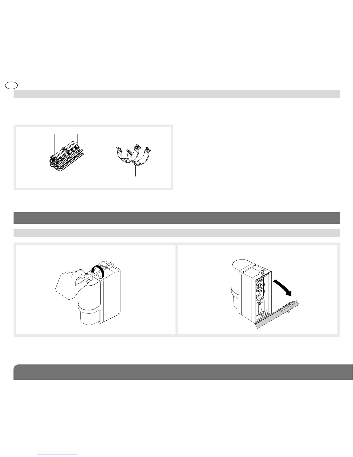
1.3 Accessories
• Barrier beam units,without radio
For the installation of additional chained or stacked infra
red transmitter or receiver modules:
- 4 gland inserts,
- 4 joint seals,
- 4 terminal blocks
• Accessories not provided:
wall fixing anchors, mounting poles, interconnect wire or
cables.
Screws M3×8: 6Screws M4×30: 4
U collars: 2U collar attachments: 6
1. Loosen the back box screw. 2. Remove the mounting box.
2.1 Opening the back box
2. Preparation
1
2
•
Barrier beam box, post fixing kit (with & without radio
transmitter)
1 pack containing:
219
GB
2.2 Opening cover
1
2
3
2.3 Guarantee label
1. Loosen the cover screw. 2. Release the cover from the bottom.
3. Rotate & remove upwards.
Coller sur certif
SH100AX
A1131A05789
SH100AX
A0113A05789
Guarantee label
Connector block
(radio module only)
TRANSMITTER
RECEIVER
TRANSMITTER module
RECEIVER module
Remove the pre-cut part of the
sticker and stick it to the
guarantee certificate in the user
manual supplied with the control
panel. If you are adding the siren
to an existing system, use the
guarantee sticker provided with
this product.
220
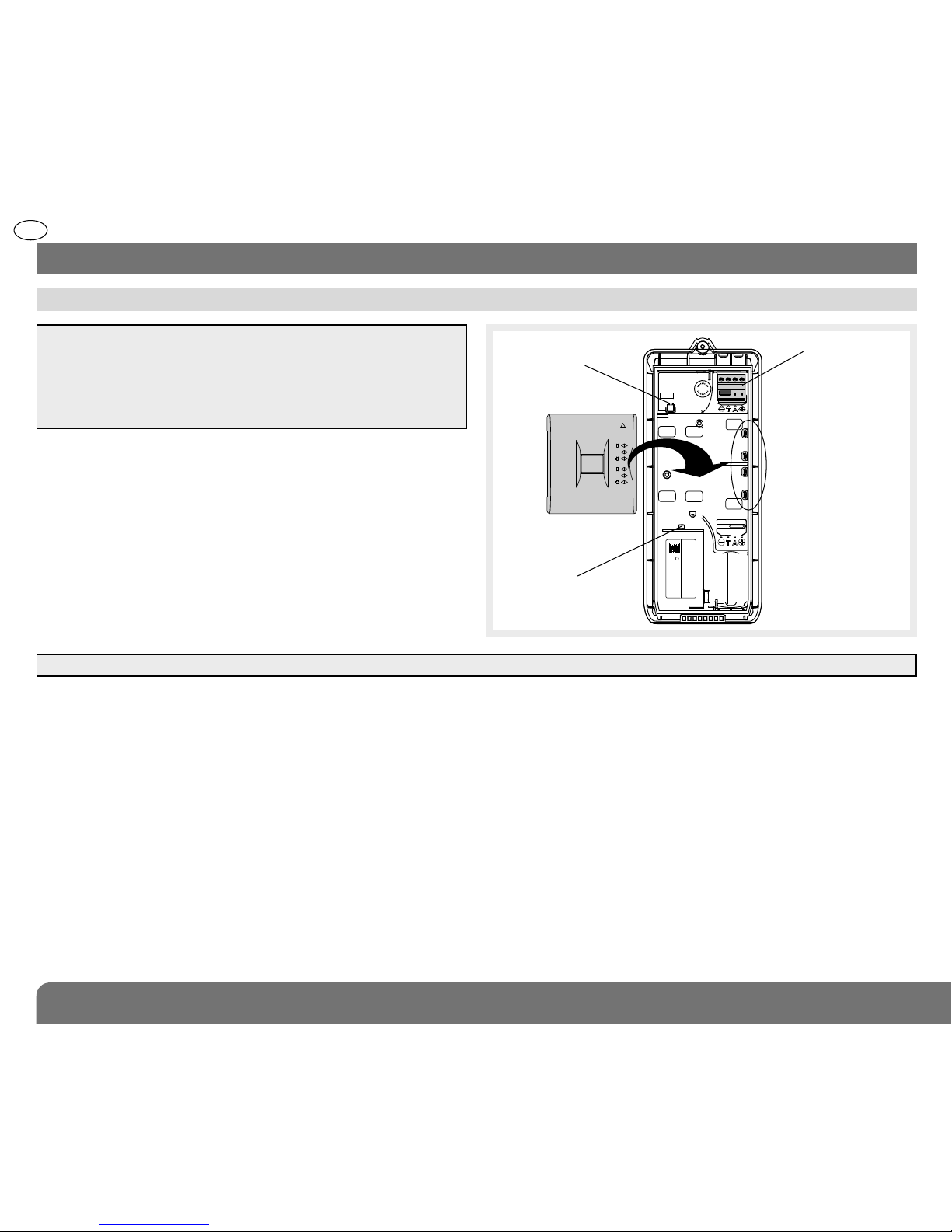
GB
1. Insert the battery in the position shown in the diagram.
2. Push firmly on the battery to ensure good connection.
On connecting the battery, only the infra red receiver and
transmitter units with radio transmitters carry out an autotest:
• if the autotest is correct, the indicator lights for 2 s,
• if faulty, the indicator flashes every 5 s.
3.1 Power supply
3. Preparation of the wireless transmitters & receivers (SH102AX or SH103AX)
SH102AX
A1131A05789
Push button
Battery contacts
Terminal block
(radio module
only)
LED
Battery
NOTE: to identify the models with built-in radio transmitters
SH102AX & SH103AX:
• refer to the reference printed on the product label located
on the back box
• only the push-button, of the models with the built-in radio
transmitters is active, once powered.
ATTENTION: when the base is de-mounted, the battery connection is not maintained.
221
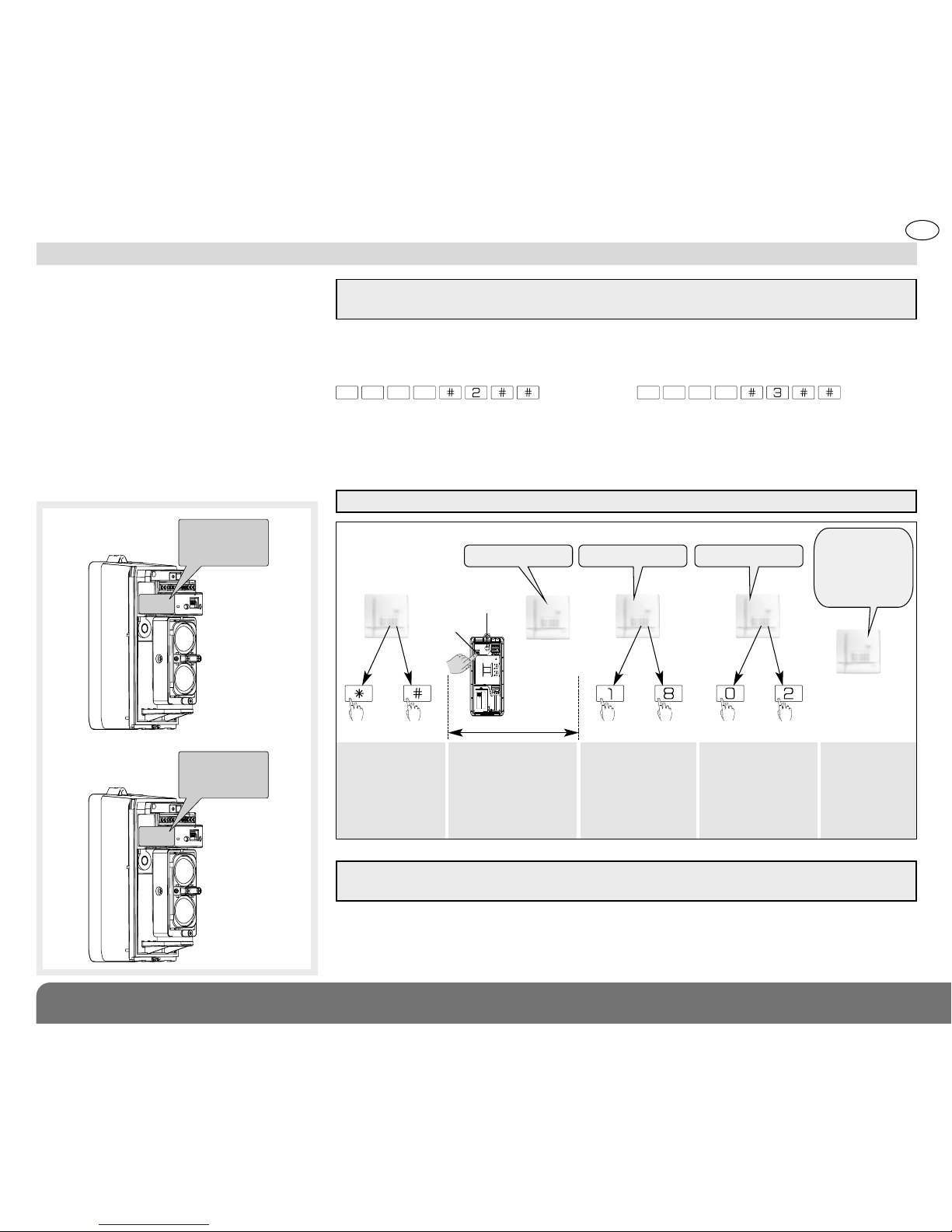
GB
The programming/learning-in of the radio
transmitters of the Infra red beams
establishes their recognition and identity
within the control panel memory.
As each radio of the infra red beam
transmitter/receiver pairs is learned, the
control panel allocates a detector
number in the chronological order of them
being memorised (within the capacity of
that model of control panel, check the
control panel specification for further
information).
3.2 Programming the wireless modules
RECEIVER
TRANSMITTER
Infra red receiver with
radio “RECEIVER”
Infra red transmitter
with radio
“TRANSMITTER”
To Learn-in a wireless barrier beam system:
Select the control panel into “Installation mode” by entering the following sequence
into the control panel key board:
then enter
1. To learn-in the radio transmitter of the Infra red receiver identified by the label
“RECEIVER”.
Carry out the following sequence using the control panel keypad:
master code installer code
* According to the model of the control panel.
ATTENTION: the control panel signals a learning error with 3 quick beeps; in this case
return to the beginning of the Learning phase above.
ATTENTION: the push button is only active in Infra red transmitters and receivers with radio modules.
Press *then #
on the control
panel keypad
2. Repeat the procedure to learn-in the radio transmitter of the Infra red
transmitter identified by the label “TRANSMITTER”. The radio transmitters of an
infra red beam transmitter & receiver pair MUST be allocated to the same group and
be allocated with the same “delay” or “immediate” designation.
Press & hold the push
button until the control
panel responds
ATTENTION: when learning-in the Infra red radio transmitter units into the control panel,
make certain they are at least 2 metres away from the control panel.
The control panel
waits for the choice
of group: 1 to 8*.
The selection is
carried out on the
control panel keypad
The control waits for
the choice of delay:
0: immediate
1: delayed
2: combined
Use the control panel
keypad to select
the type
The control panel
confirms with
a vocal message
that it has
learned/
memorised
the detector/
Infra red beam
SH100AX
A1131A05789
10 s max.
“beep, detector
X, group Y
immediate
(or delayed
or combined)”
))
)
)
)
“detector X”
*
AP
BP
then to to
“delay?”“group?”
222
GB
3.3 Voice identification message recording
x
In order to easily identify the beams and their columns it is possible to record individual vocal messages of 3 seconds duration at the
control panel for each of the radio transmitters and so identify the single barrier beam or stacked/chained beam. A table is available at
the end of the manual to in order to note the messages and the position of their respective beams or columns.
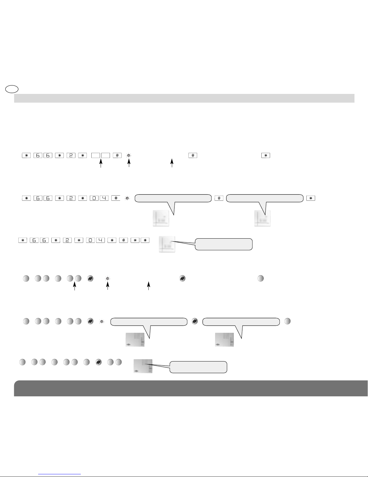
• With a control panel fitted with software version 2.0.0 and later
(to know which software version you have, use the control panel keypad to check it by entering : # 5 0 3 # #)
- To record the message:
- Example of individual message: “detector 4, beam 1, receiver column”, dial:
To verify the identification message, dial:
“record the message” “playing recorded message”
“detector 4, beam 1, receiver column” “detector 4, beam 1, receiver column”
• With a control panel fitted with a software version below to 2.0.0
- To record the message:
- Example of individual message: “detector 4, beam 1, receiver column”, dial:
To verify the identification message, dial:
Q
6
6
Q
“record the message”
“playing recorded message”
Q
Q
6
6
Q
0
4
Q
Q
6
6
Q
0
4
QQQ
“detector 4, beam 1, receiver column”“detector 4, beam 1, receiver column”
speak into the
microphone
No. of detector from 01 to 80
(depending on the model of the
control panel & its max number of zones)
wait for the LED to light
before speaking the message
into the microphone
speak into the
microphone
No. of detector from 01 to 80
(depending on the model of the control
panel & its max number of zones)
wait for the LED to light
before speaking the message
into the microphone
“detector 4, beam 1,
receiver column”
x
“detector 4, beam 1,
receiver column”
223
GB
3.4 Wireless receiver alarm level parameter setting
The factory default setting for the infra red receiver, with radio, is “deterrence” (for system capabilities refer to the Installation guide
accompanying your control panel).
NOTE: if you wish an Intrusion alarm to be signalled by the control panel programme parameter 5 to value “1”, see table below.
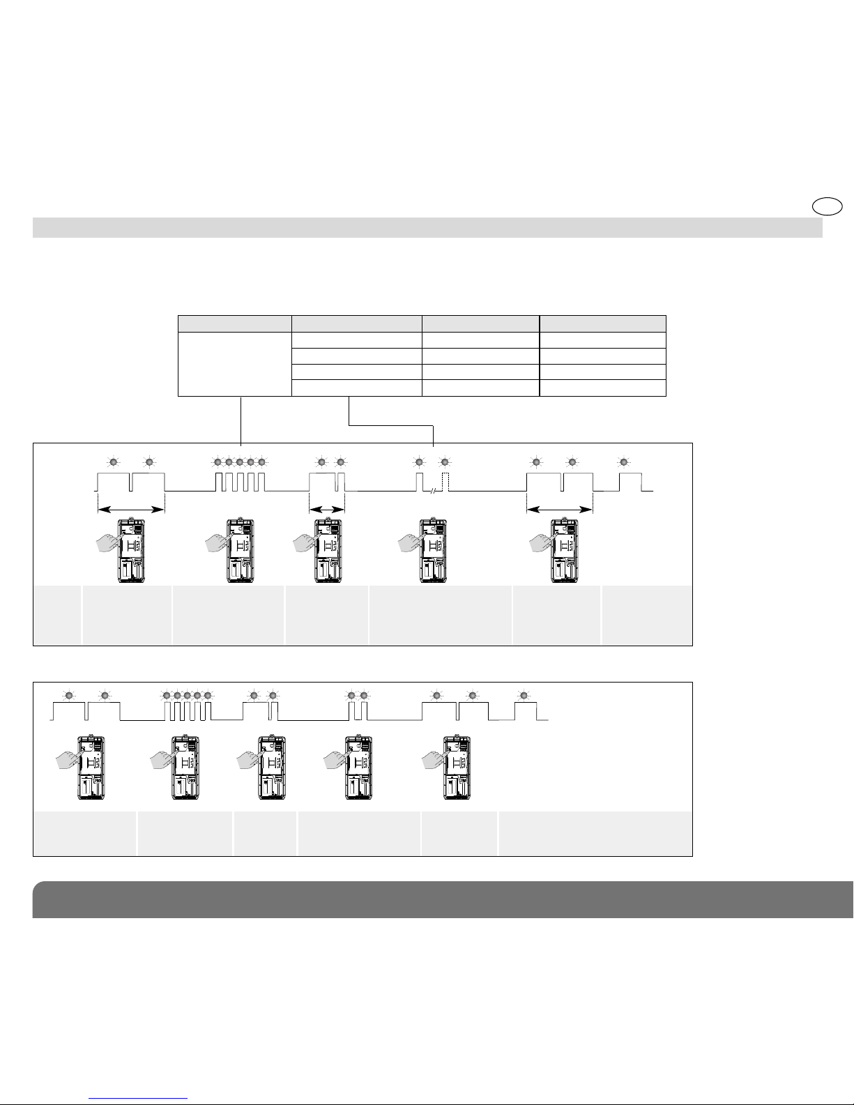
It is possible to change the alarm level setting using the following sequence:
Parameter No. Value of parameter Alarm management Alarm level
5 1 yes intrusion
2 yes prealert
3 (factory default) yes deterrence
4 yes warning
Programming sequence
Programming
LED unlit
Programming
LED lit
Pressing
sequence
approx.
5 s.
approx. 10 s. approx. 2 s.approx. 10 sec
Begin
the sequence
by pressing
& holding until the
LED extinguishes
5 successive
presses
corresponding
to the parameter
number
Press & hold
until LED
extinguishes
1 to 4 presses
corresponding to the desired
parameter value
End
the sequence
by pressing
& holding until the
LED extinguishes
LED remains
ON =
parameter
correctly
programmed
{
Begin 5 presses to select
parameter 5,
“Alarm level”
Press & hold
until LED
extinguishes
2 presses
to select value 2,
“Prealert” alarm level
End
Programming example: programming the infra red receiver module with an alarm level “Prealert”: parameter No. 5, parameter value 2.
5 2
2 s. env.
SH100AX
A1131A05789
SH100AX
A1131A05789
SH100AX
A1131A05789
SH100AX
A1131A05789
SH100AX
A1131A05789
SH100AX
A1131A05789
SH100AX
A1131A05789
SH100AX
A1131A05789
SH100AX
A1131A05789
SH100AX
A1131A05789
{
ATTENTION: for external applications it is strongly suggested that parameter 45 in the control panel is set at value 1, 2, 3 or 4, “Arming
Blocked”.
224
GB
3.5 Arming with a beam blocked (in alarm) or an anomaly
If an obstacle (leaves, animals etc.) is present in the path of an infra-red ray (2 beams) or in the event of misalignment of a barrier,
when the control panel is switched on, the control panel will announce this problem with the message “Beep, detector X open” or
“Beep, ON, detector X open”.
3.5.1 Arming the control panel, with an obstacle blocking an infra red barrier (2 beams) when the control panel is
programmed with “Inhibition of Arming”
(see. control panel Instruction manual, Switch ON/Arming inhibition, system parameter 45 at value 1, 2, 3 or 4)
The control panel can be programmed to prohibit the Arming of the system in the event of masking or misalignment of the beam
barrier (detector(s) open). With the Arming of the system, the control panel announces the fault with the message “Beep, detector X
open”. In this case, the system could only be started if there is no masking or misalignment of the beam barrier.
3.5.2 Arming with an obstacle blocking a beam barrier (2 beams) when the control panel “Arming Blocked “ is inactive
(control panel parameter 45 set at value 0)
In the case where “Arming Blocked” is selected “Inactive” (parameter 45 set at 0), a fault or blockage is announced at Arming by the
message “Beep, ON, detector X Open”, and the system will proceed to be Armed.
Inhibition of a (faulty/blocked) beam barrier when “Arming Blocked” is set at “Inactive”:
1. Detector/beam barrier inhibit
In factory default (control panel parameter 61 is set at 0) so that if a detector/beam barrier remains open/ blocked (or if the infra red
module repeatedly alarms) the control panel automatically inhibits the detector/barrier concerned at the end of the Exit time delay
(factory default 90 seconds) and announces “Beep, ON, detector X inhibited”. The beam barrier will then be ignored/inactive for that
armed period.
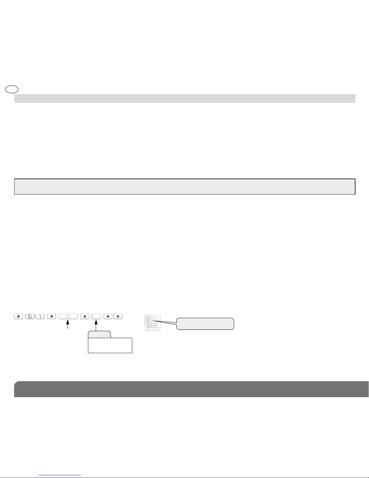
2. Detector/beam barrier non-inhibitable
Automatic inhibition can be removed by selecting the control panel parameter 62 to value 1.
In this case if a detector/beam barrier remains open when arming is initiated (or an infra red module repeatedly triggers alarms),
it would not be inhibited and would remain active at the end of the exit/arming delay period.
In order to remove auto inhibit, enter the following:
Factory default: detector/barrier inhibitable
No. of the learned
in detector
(Radio Receiver
of the infra red
beam/barrier)
Value
• 0: inhibitable
• 1: non-inhibitable
“beep, detector X, 0 or 1”
225
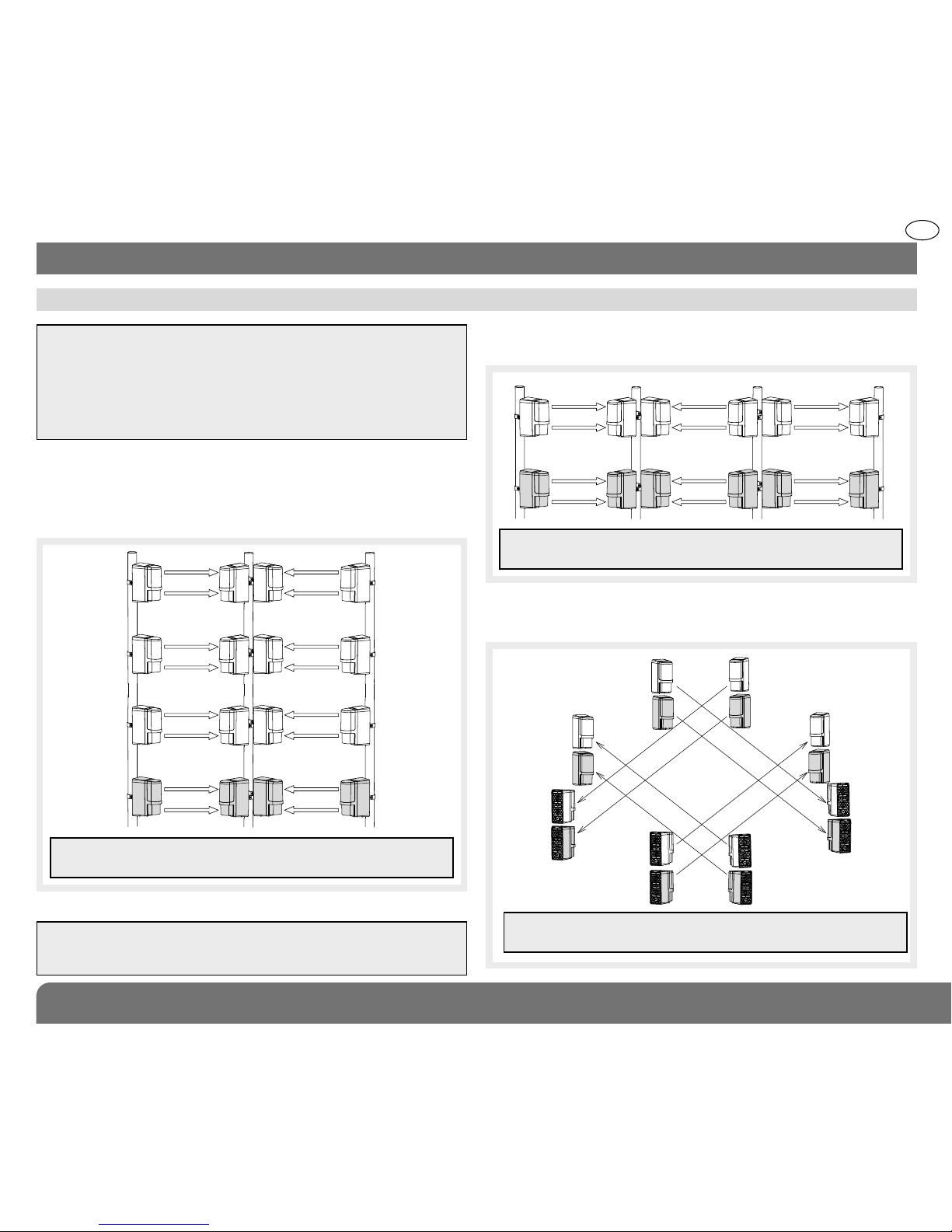
4.1 Choice of module positioning for various types of protection
4. Infra red barrier installation
ATTENTION: to avoid the infra red interferences which can occur,
when several infra red modulesare used on one long distance
or in the applications with chaining/stacking of modules to form
a column or tower barrier, it is necessary, in in the planning stage
to consider:
• the maximum number of modules that can be chained/stacked,
• the site of the IR receivers compared to the IR transmitters.
Attention: do not attempt to install other types of IR beams with
these units. The system will not function correctly due to probable
IR interference and cause false alarms.
Transmitter Receiver
Receiver
Transmitter Transmitter Receiver
Transmitter Receiver Receiver Transmitter Transmitter Receiver
ATTENTION: stacks of more than 2 twin beam modules is not
possible in this example.
Transmitter
Transmitter
Receiver
Transmitter
Transmitter
Receiver
Receiver
Transmitter
Transmitter
Receiver
Receiver
Receiver
Transmitter
Transmitter
Receiver
Receiver
ATTENTION: stacks of more than 2 twin beam modules is not
possible in this example.
In the following example schemes the IR modules with radio
modules are coloured grey.
1.
2 barriers each with a maximum stack/chain of 4 modules
(twin beam IR units).
2. Long distance detection barrier with stacking of 2 twin beam
modules per barrier.
3. Perimeter protection with stacking of 2 IR modules for each
barrier.
Transmitter Transmitter
Receiver Receiver
Transmitter Transmitter
Receiver Receiver
Transmitter Transmitter
Receiver Receiver
Transmitter Transmitter
Receiver Receiver
ATTENTION: a stack/chain of more than 4 modules is not
possible in this example.
GB
 Loading...