

DAITEM SC901AU, SC902AU, SC906AU, SC100AU, SC200AU Installation Manual
...
Doorphone
INSTALLATION MANUAL
SC901AU / SC902AU
/ SC906AU
SC100AU
SC200AU / SC201AU
/ SC206AX
MHF01X / MHF02X
MHF03X / MHF04X
MHF05X / MHF06X

2
This manual describes how to install the following products:
SC901AU Mains/mains code-operated 1-home doorphone kit
SC902AU Lithium/mains 1-button 1-home doorphone kit
SC906AU Battery/mains 1-button 1-home doorphone kit
SC100AU Interior handset unit + base + EU power pack
SC200AU Mains controller
SC201AU Lithium battery-operated controller
SC206AX Dry battery controller
MHF01X Translucent 2-home outdoor caller unit
MHF02X Translucent code-operated 2-home outdoor caller unit
MHF03X Opaque 1-home outdoor caller unit
MHF04X Opaque 2-home outdoor caller unit
MHF05X Opaque code-operated 1-home outdoor caller unit
MHF06X Opaque code-operated 2-home outdoor caller unit
The doorphone system can be used to welcome and filter visitors, listen in to background sounds
at each access point and communicate with another handset.
It can also be used to remotely control:
• one or several electrical latches,
• one or several automatic gate control systems,
• one or several automatic garage door control systems,
• one or several lights.
It also allows users to check the status of access points or lights using the screen on the handset
at any time.
Several additional interior handset units can be added to the doorphone system (maximum of 4
per call button).
Foreword

3
Contents
1. Introduction................................................................................................................................. 4
2. Description.................................................................................................................................. 6
2.1 Outdoor system ..................................................................................................................... 6
2.2 Interior handset unit ............................................................................................................... 7
3. Tooling required ....................................................................................................................... 11
4. Preparation ............................................................................................................................... 12
4.1 Guarantee stickers............................................................................................................... 12
4.2 Charging the handset before installation ............................................................................13
5. Installing the outdoor system ................................................................................................ 16
5.1 Installing the outdoor caller unit .......................................................................................... 16
5.2 Installing the controller......................................................................................................... 21
5.3 Connecting the equipment.................................................................................................. 22
5.4 Powering the controller........................................................................................................ 24
5.5 Creating the radio link between the handset and the controller ........................................ 28
6. Testing the radio range........................................................................................................... 31
7. Installing the interior handset unit......................................................................................... 32
7.1 On a table............................................................................................................................. 32
7.2 On a wall............................................................................................................................... 32
8. Testing operation ..................................................................................................................... 36
8.1 Testing communication with each interior handset unit..................................................... 36
8.2 Testing access controls ....................................................................................................... 37
9. Appendices............................................................................................................................... 38
9.1 General information about creating the radio link............................................................... 38
9.2 Testing the radio link ............................................................................................................ 55
9.3 Deleting radio links and returning to factory programming................................................ 57
10. Changing the batteries ......................................................................................................... 61
10.1 In the main controller ......................................................................................................... 61
10.2 In the handset .................................................................................................................... 64
11. Questions – Answers............................................................................................................. 65
12. Technical data ........................................................................................................................ 67
4
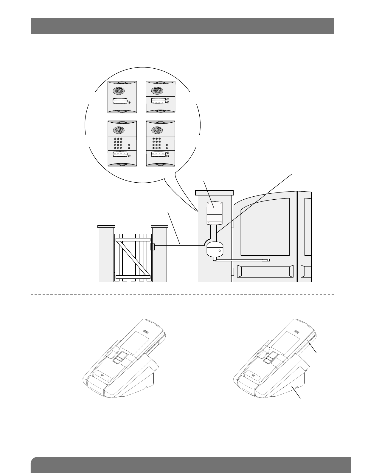
DOORPHONE SYSTEM COMPONENTS
OUTDOOR SYSTEM
INTERIOR
HANDSET UNIT
1 call button
+ tag reader
1 call button with keypad
+ tag reader
2 call buttons
+ tag reader
2 call buttons with keypad
+ tag reader
Connection of an
electrical latch or lock
Handset units can
communicate with each
other (inter-handset
communication function)
Handset
Base
Outdoor caller units wired to main
controller (road side)
Main controller
(garden side)
Connection of gate
motorisation system
) ) ) ) ) ) ) ) ) ) ) ) ) ) ) )
) ) ) ) ) ) ) ) ) ) ) ) ) ) ) )
1. Introduction
5
Each kit comprises the following (minimum):
• An outdoor caller unit installed on the road side, for visitors.
• A controller installed on the same pillar but on the garden side. This controller provides:
- the radio link with the interior handset unit,
- the power supply to the outdoor caller unit and controller,
- the connections to the electrical lock or latch and gate motorisation system.
These products are connected via a cable that either goes through or around the pillar.
• An interior handset unit (base and handset) for receiving calls and remotely controlling:
- the electrical locks or latches,
- the gate motorisation system,
- the automatic garage door control system (1),
- lighting (1),
- communication with another handset (2),
- doorphone programming.
Using the outdoor caller unit, access is controlled using:
• an access code,
• a tag reader.
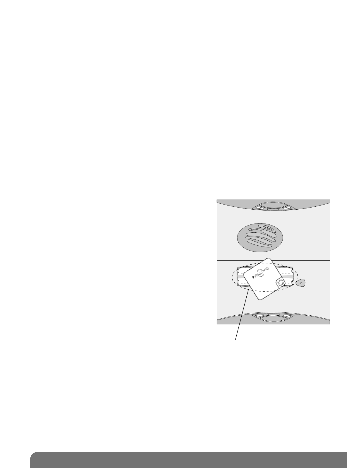
Identifying each user with a tag
The outdoor caller units have a front panel with a tag
reading zone allowing each user to control access quickly
once the tag has been identified.
Holding the tag up to the name label dispenses the user
from entering the access code.
The outdoor caller unit with keypad can manage up to 16
different tags. Each tag must be registered on the caller
unit.
1) Via output receiver.
2) Requires a minimum of 2 handsets.
The tag is detected in this zone
Mr et Mme Evêque-Mourroux
6
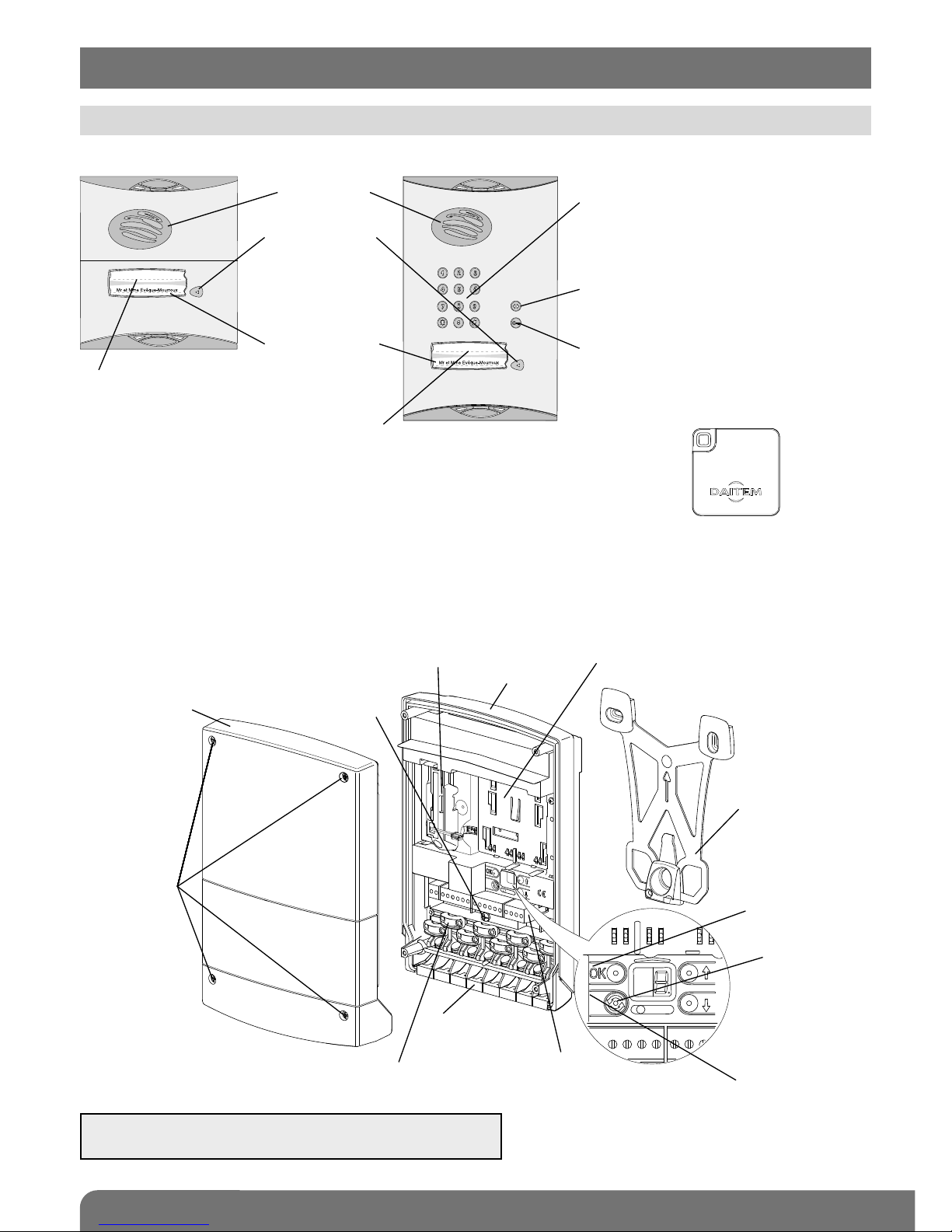
2. Description
Validation button
Radio link creation
button
Slot for battery (supplied with SC201AX,
optional for SC200AX)
Battery
Radio link
creation LED
4 captive
screws for
closing the
cover
Cover
Controller base
Fixing bracket
Connection
terminal blocks
Captive screws
for bracket fixing
Cable clamp
(do not remove)
Grommet
(remove)
2.1.2 Controller
• Mains-powered controller or Lithium battery controller
IMPORTANT: the grommets, cable clamps and screws
for the cable clamps are in the bag of accessories.
Loudspeaker
Call button
(1 or 2 depending
on model)
4 handsets max.
per button
Blank label
for user’s name
(sheet of labels
supplied)
Tag reading zone
Tag reading zone
Programming keypad for
entering access code to allow
pedestrians and cars to enter
Gate access control button
Latch/side gate access
control button
2.1.1 Outdoor caller units with armoured cover
2.1 Outdoor system
Tag (1 or 2 tags per kit
depending on the model)
7
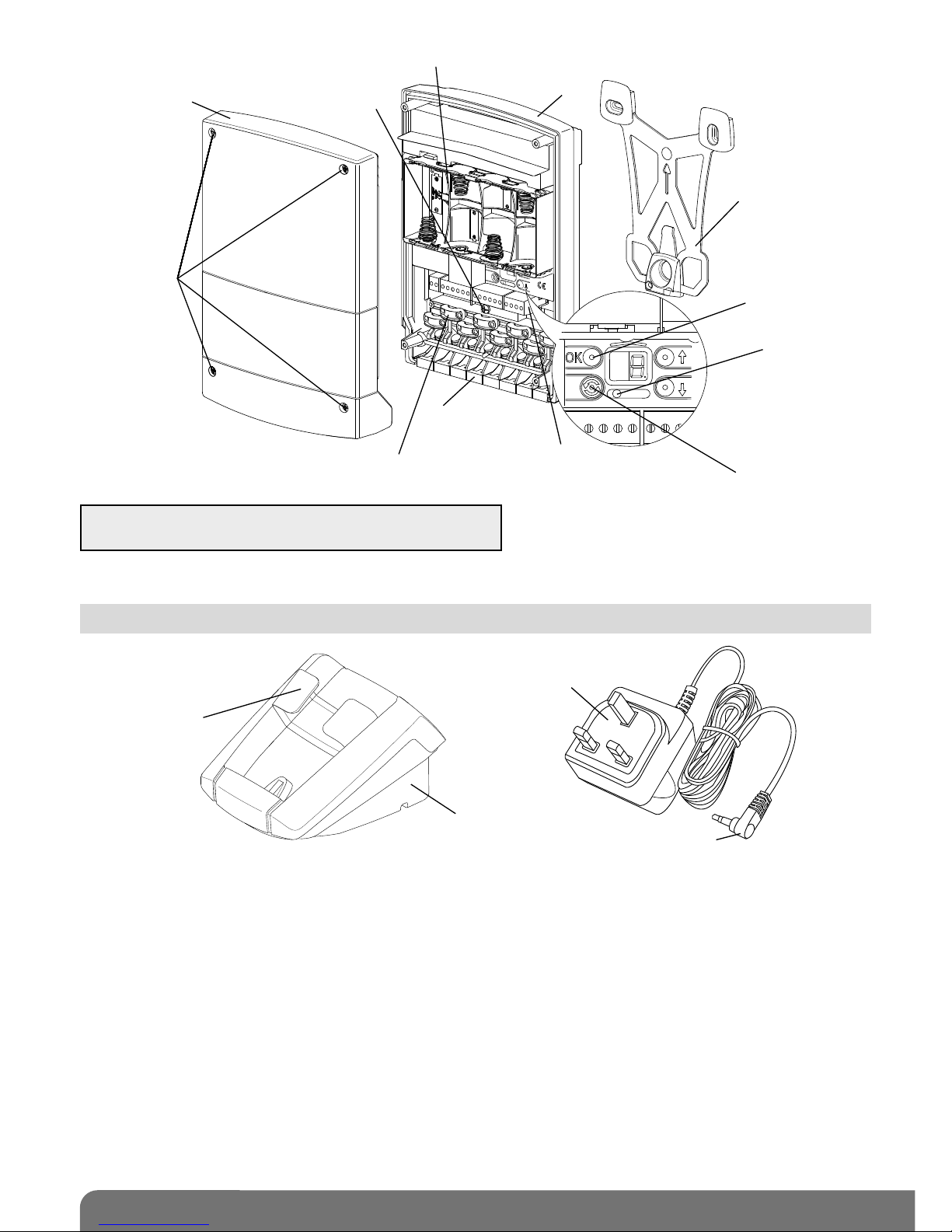
2.2.1 Base
Handset base
Power pack
Base connection jack
Transparent
removable cover
2.2 Interior handset unit
IMPORTANT: the grommets, cable clamps and screws
for the cable clamps are in the bag of accessories.
• Alkaline batteries controller
Validation
button
Radio link creation
button
Slot for batteries (LR20 type, not supplied)
Radio link
creation LED
4 captive
screws
for closing
the cover
Cover
Controller base
Fixing bracket
Connection
terminal blocks
Captive screws
for bracket fixing
Cable clamp
(do not remove)
Grommet
(remove)
8
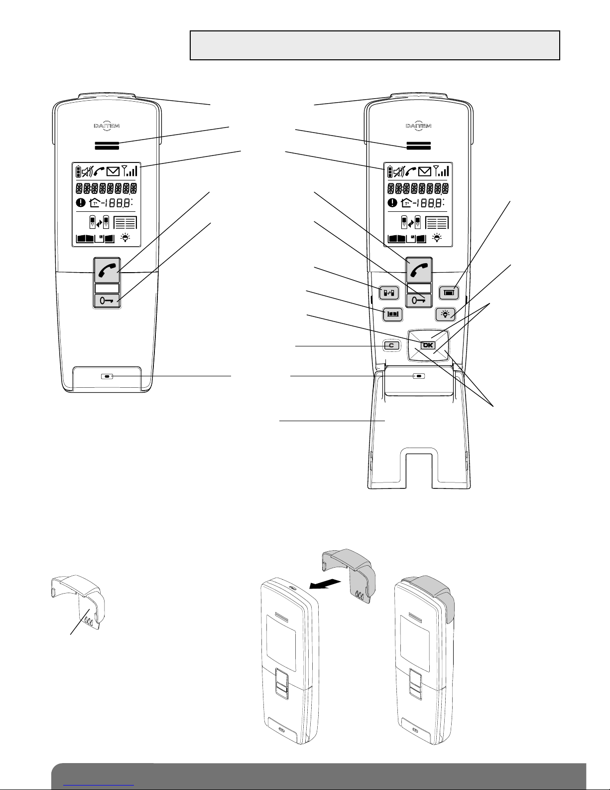
2.2.2 Handset unit
C
F
C
F
Cover closed
Belt clip
Cover open
Removable belt clip
Loudspeaker
Display
Communication button
Latch/side gate control
button
Inter-handset
communication button
Gate control button
Validate button (OK)
Cancel button
Microphone
Flip cover
Garage
control button
(1)
Lighting
control button
(1)
Up and down
scroll keys
Left and right
scroll keys
Backlighting is activated whenever a button is pressed.
It goes out again after 5 seconds when no other button
is pressed.
(1) These functions require a relay output receiver to be installed.
IMPORTANT: when installing the system, the handset(s) must be charged on
their base before they can be used.
Belt clip
If necessary, fit the
belt clip to the handset
as shown:
9
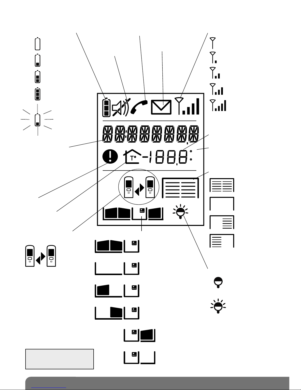
2.2.4 Display description
C
F
flat
needs
charging
charging
recommended
fully charged
charging
Scrolling text zone:
- display of time
- outdoor temperature
- faults
- access calling
- current commands
- handset mode
Fault
Handset in inter-handset
communication mode
Handset battery status
Handset
in silent mode
Communication in progress
Missed call
no signal
poor
average
good
excellent
Radio range
lighting off
lighting on
Lighting status
Garage, side gate and latch status
gate closed
gate open
gate 1 open/2 closed
or gate half open
if sliding motor
gate 1 closed/2 open
or side gate open
latch closed
latch open
Garage status
Indoor temperature
indication
Temperature unit:
- °C: Celsius
- °F: Fahrenheit
Indoor temperature
garages
closed
garages
open
garage
1 open
2 closed
garage
1 closed
2 open
IMPORTANT: only the icons
corresponding to the
installation are displayed.

10
C
2.2.5 Handset display in standby mode (general information screen)
Handset
battery status
Time
Gate, side gate
and latch status
Lighting status
Garage status
Indication of the indoor
temperature
The temperature displayed is
the temperature measured on
the handset and is updated
every 10 minutes
Indication of the outdoor
temperature
The temperature displayed is
the temperature measured at
the first access point
programmed and is updated
every 10 minutes
11
GUARANTEE
The conditions according to which the guarantee and after sales service apply are described in the general
price list and can be sent on request.
Some after sales service products and accessories, such as:
• MHU01U power pack
• SC501AX interior handset unit base
• SC501AX belt clip
• SC801AX handset flip cover
(non-exhaustive list for indication purposes only) have a 2-year manufacturer guarantee, which cannot be
extended.
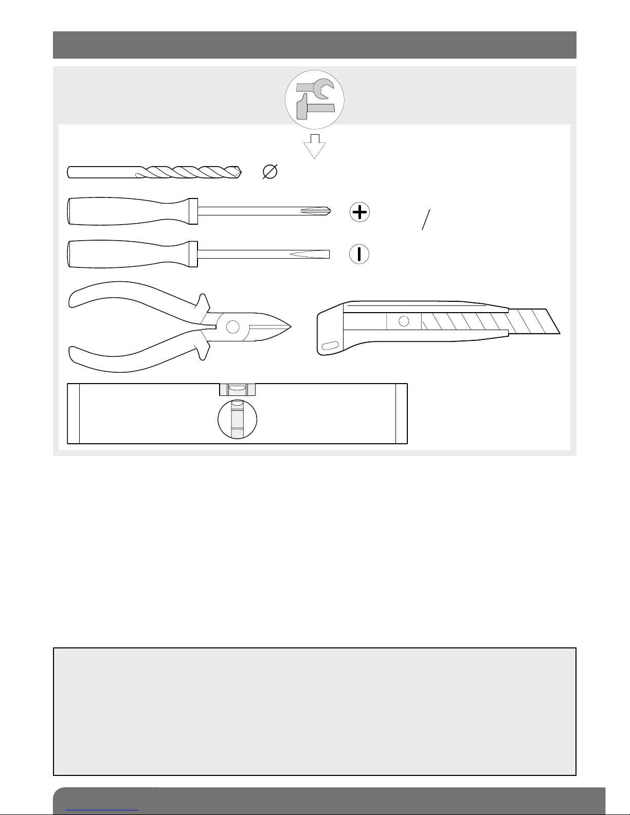
6/8 mm
3.5 mm
PZ 0
3 mm
PZ 2
6 mm
3. Tooling required
12
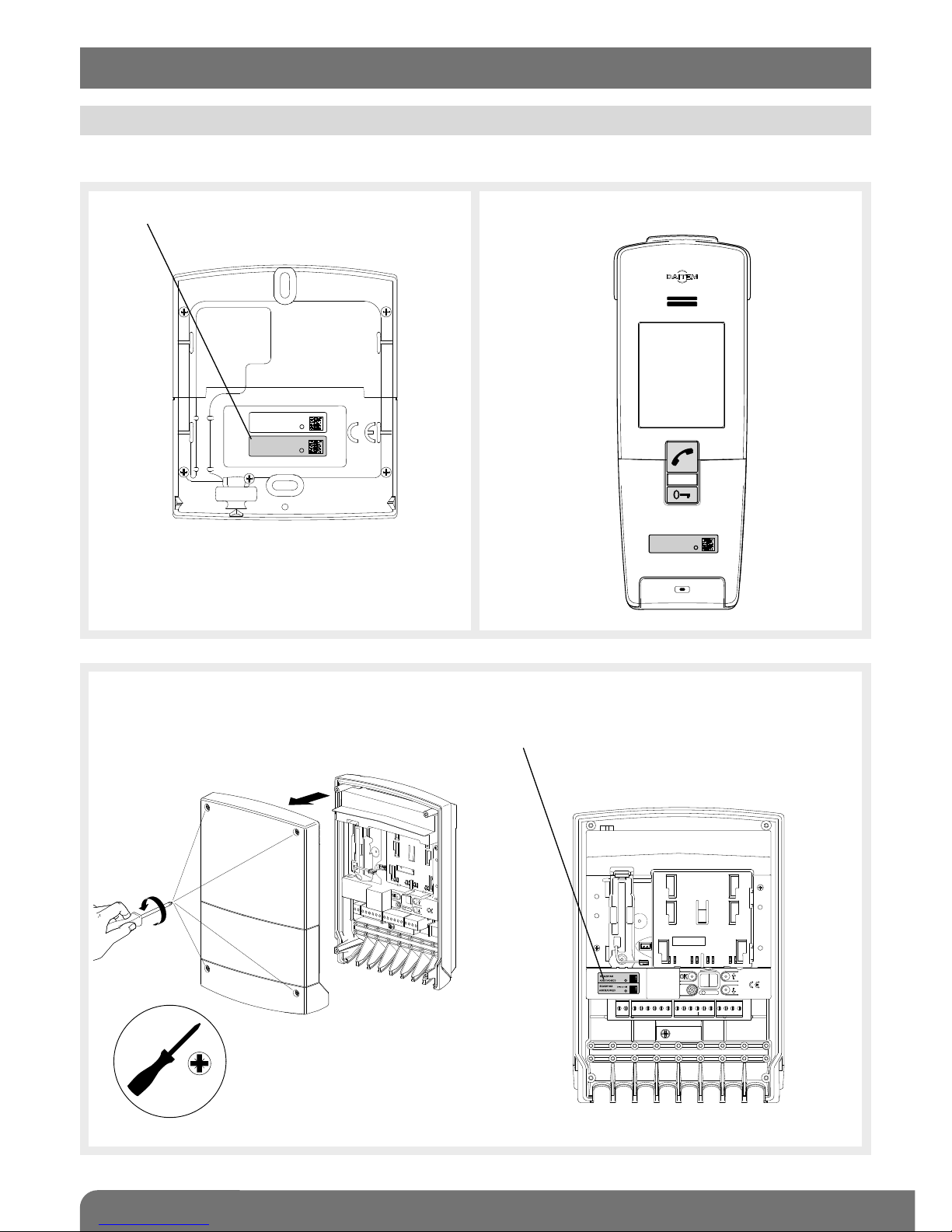
Remove the pre-cut parts of the stickers and stick these to the extension request supplied.
On the back of the caller unit On the handset
SCA100AF
A0831A04823
Coller sur certif
Inside the controller
1. Unscrew the 4 cover screws
and open the controller.
2. Remove the pre-cut part.
Pozidriv 2
4. Preparation
4.1 Guarantee stickers
MHF01X
A0831A04823
Coller sur certif
MHF01X
A0831A04823

13
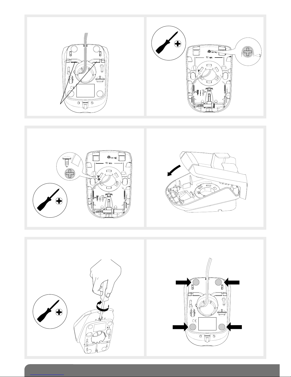
3. Rotate the back of the base until it is in “table” position.
4. Thread the power pack jack through the
hole.
5. Connect the jack to the base making sure
that the cable is positioned in the
designated slot.
Thread the cable
through here
Alternative cable
passage
IMPORTANT: when installing the system, the handset(s) must be charged on the base before it/they can be
used.
4.2.1 Handset on mains-powered base
IMPORTANT: the MHU01U power pack supplied
must be used.
4.2 Charging the handset before installation
1. Open the base. 2. Remove the 4 anti-slip pads.
¡
¿
3.5
14
6. Thread the power cable into one of the
guides at the back of the base.
7. Unscrew the locking screw.
Alternative
guides
Pozidriv 0
Pozidriv 0
8. Screw it back into the same place hence
locking the base in “table” position.
9. Close the base.
Pozidriv 2
10. Tighten the locking screw to prevent the
base from being opened by mistake.
11. Stick the 4 anti-slip pads to the back of
the base and then put it on the table.
15
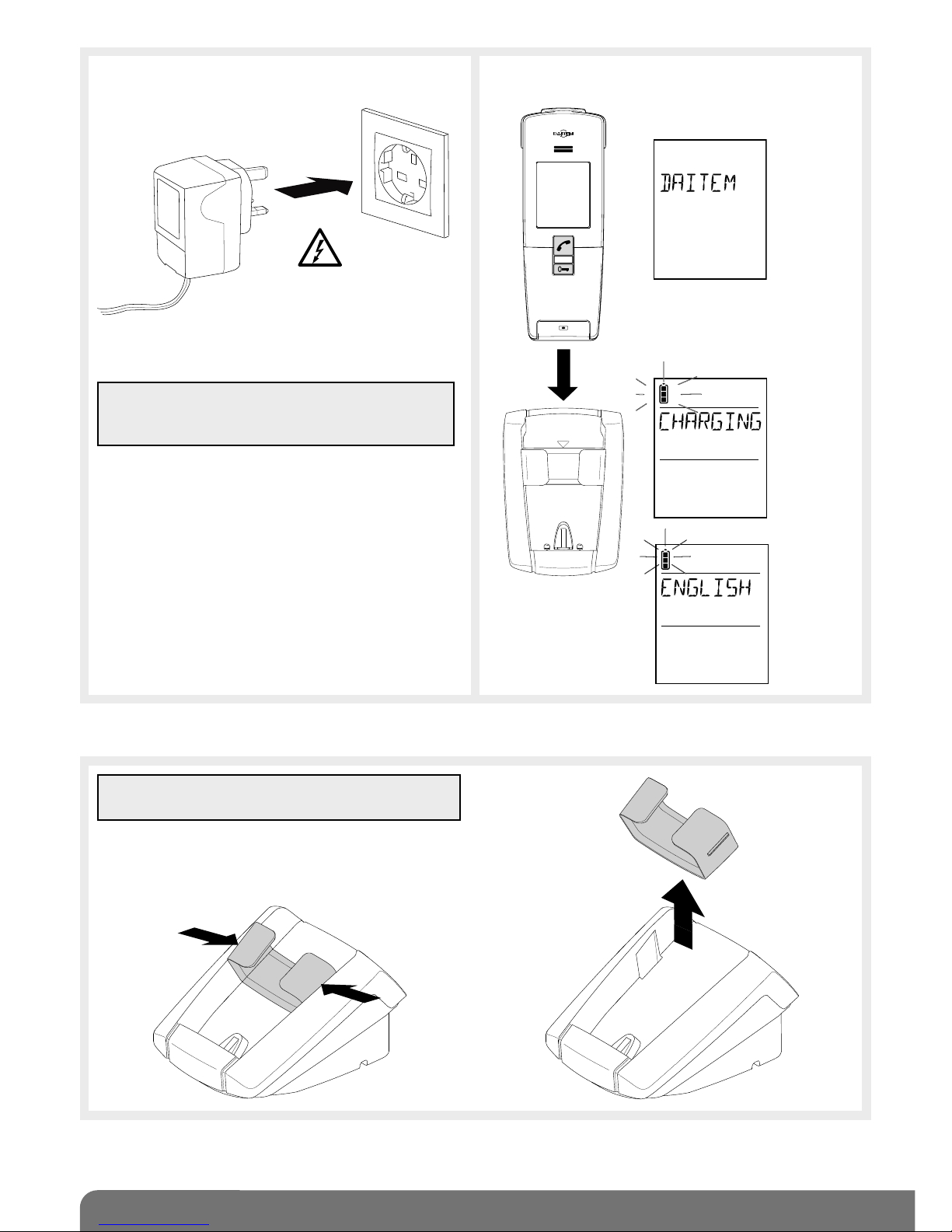
12. Connect the power pack to the mains
(220 V).
13. Put the handset on the base.
Electrical shock
hazard
TIP: to make it easier to pick the handset up, the
removable transparent cover can be removed.
The handset displays
this message for 2 sec.
Then CHARGING
if the battery is not
sufficiently charged (1).
or
If the
battery is
sufficiently
charged.
You can now move on to the next chapter describing how to install the doorphone.
¿
¡
IMPORTANT: the mains socket must remain
accessible so that the power pack can be easily
disconnected.
(1) For the rechargeable handset battery life to last its full period (15 days) when off its base, it must be left on its base to
charge for at least 2 days beforehand (during which time it can of course be used).
16
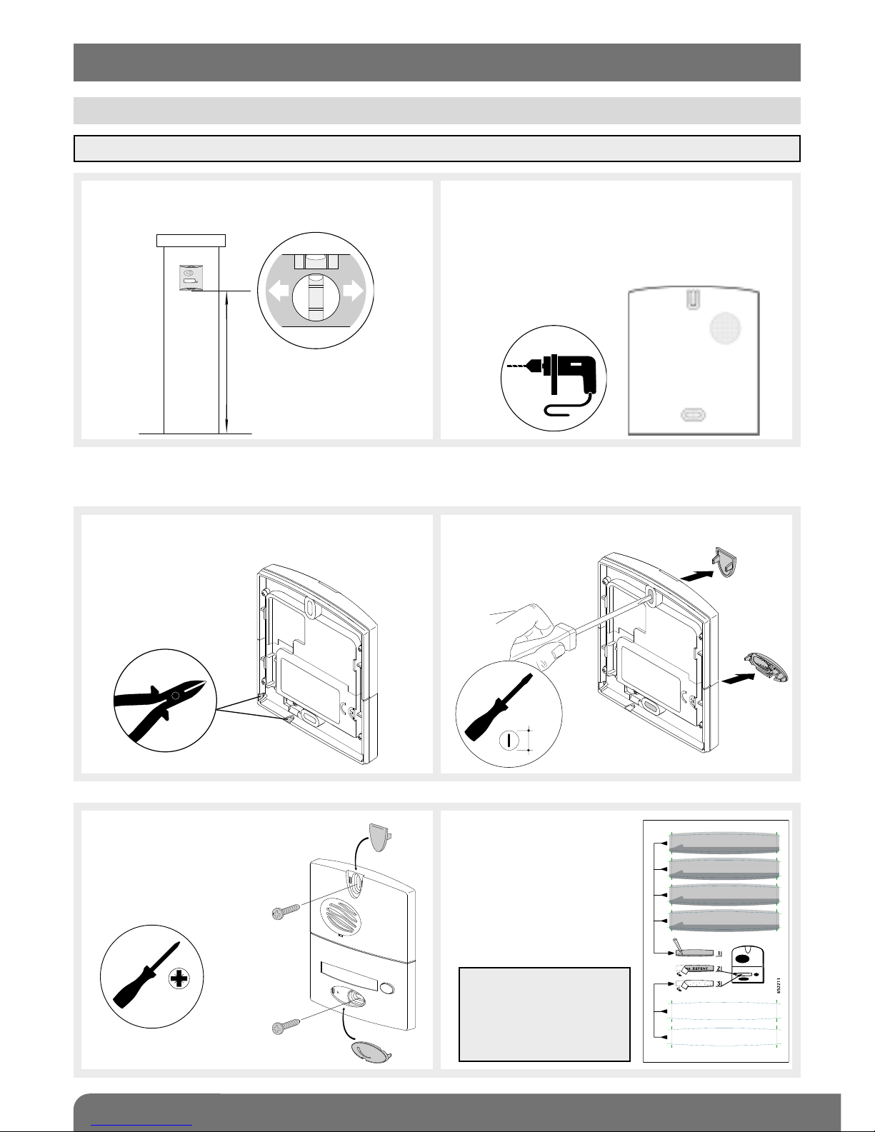
1. To ensure easy use, fix the unit at a height
of 1.20 m.
2. Mark and drill the outdoor caller unit holes
with a Ø 6 mm drill bit.
Also mark the place where the cable feed
hole has to be drilled (Ø 8 mm min.
recommended).
1.20 m
Please refer to the next chapter for mounting outdoor caller units with armoured cover.
Follow steps 3 to 6 below for units without armoured cover.
3. If the cable goes around the pillar, pierce
one of the cable knock-outs with a cutter.
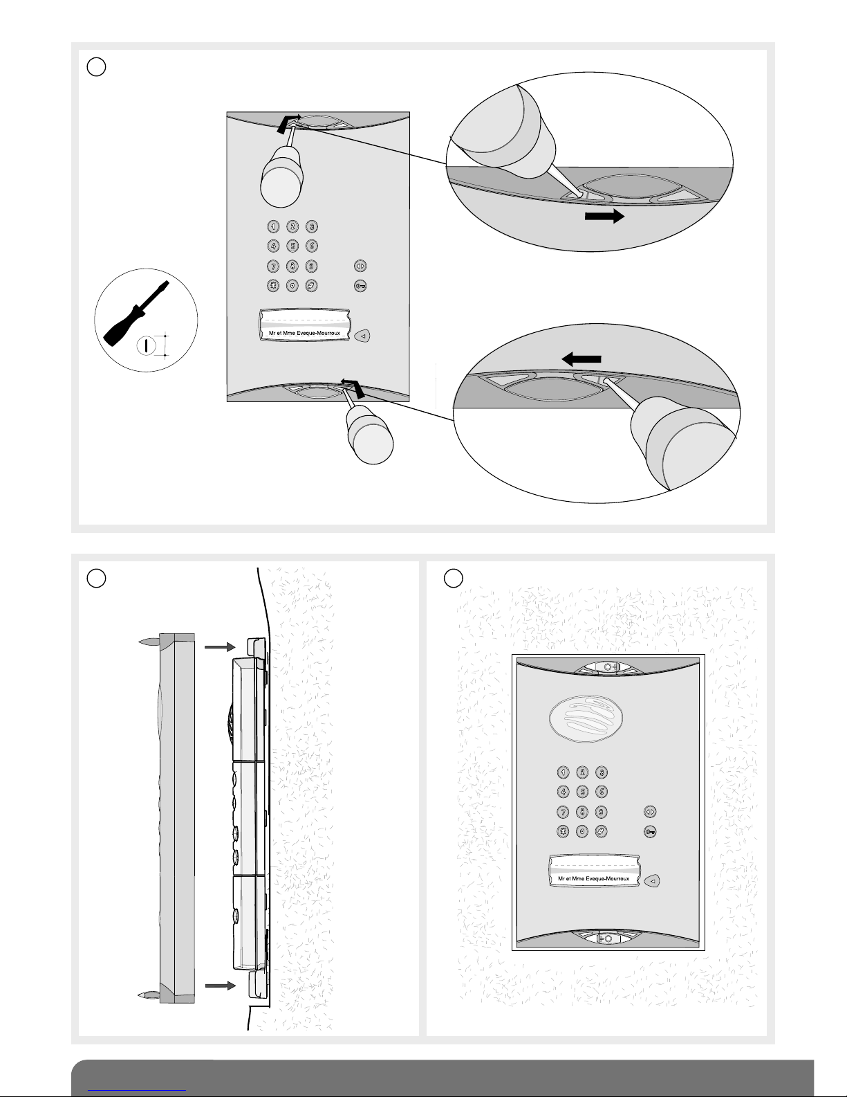
4. Push the screw covers out using a flat
screwdriver.
5. Thread the cable through the
hole knocked out in step 3
and screw the caller unit
in place. Put the
screw covers back.
6. Use a pencil or
permanent marker
to write the names.
Stick a transparent
protection label on
top.
Pozidriv 2
3.5
TIP: you can print the
labels using the
software (EtikPrint)
available on the Daitem
web site.
IMPORTANT: to ensure the outdoor caller unit remains watertight, never try to open it!
5. Installing the outdoor system
5.1 Installing the outdoor caller unit
17
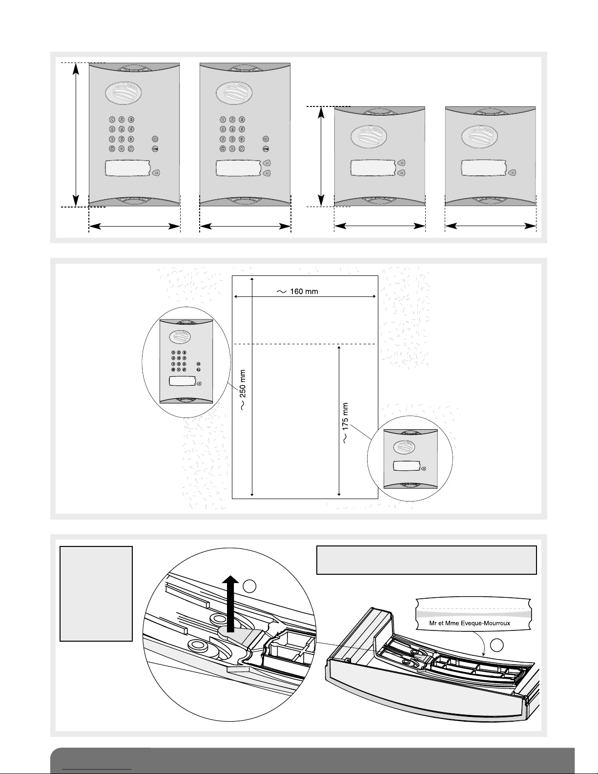
Mounting the outdoor caller units with armoured cover
232.4 mm
145 mm 145 mm
160.4 mm
145 mm 145 mm
1
2
IMPORTANT: use the label supplied and
carefully position it in the space provided.
TIP: you can
print the labels
using the
software
(EtikPrint)
available on
the Daitem
web site.

18
4
Pozidriv 2
6
3
5
19
7
8 9
3.5
20
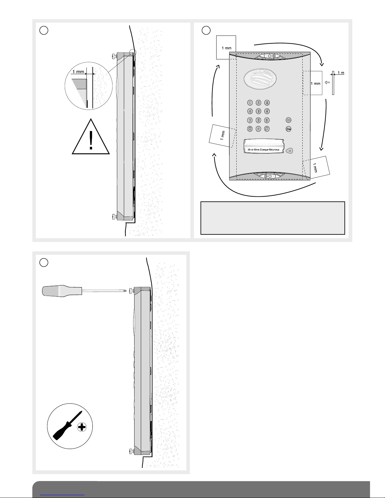
1110
12
IMPORTANT: when the armoured cover is
positioned on the unit, there should be a 1 mm
clearance (use the shim for this purpose)
between the pillar and armoured cover.
Pozidriv 2
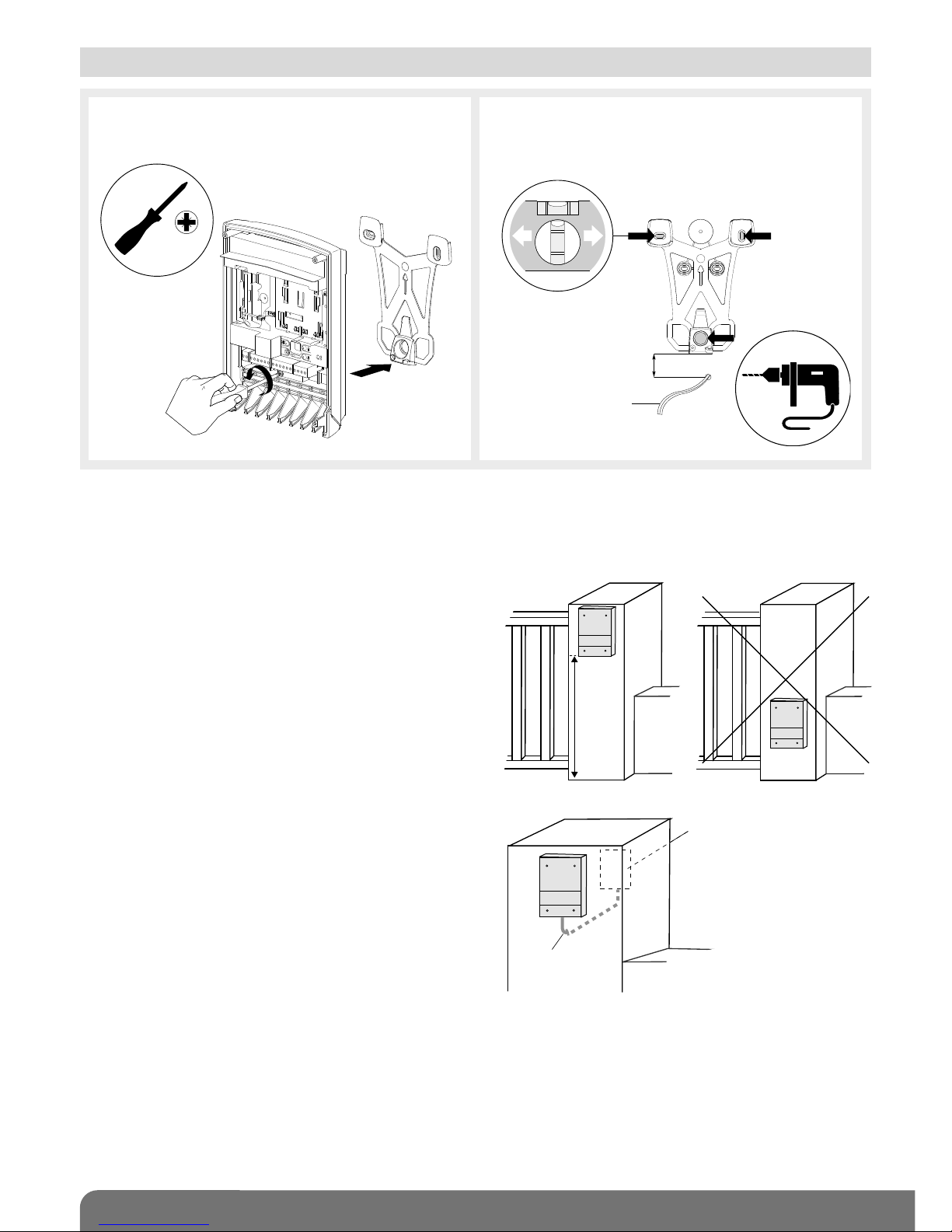
21
1. Unscrew the locking screw from the
bracket and then remove it.
2. Following the installation rules below,
mark 3 fixing points and drill a hole in the
pillar using a Ø 6 mm drill bit.
4 cm
minimum
Outdoor caller unit
cable feed
Pozidriv 2
Installation rules
To make it easier to hook the base on to the bracket choose a flat surface (or make the surface as
flat as possible) on the garden side of the pillar. This is especially important for the top part of the
bracket.
To guarantee an excellent radio range:
• keep the space clear around the controller,
• remove any dense vegetation nearby and
make sure the area is always clear,
• place the controller as high up as possible
(80 cm min.).
• make sure there are no obstacles between
the controller installation point and the house
where the handset(s) is/are installed.
Do not wind the cable up nearby or inside the
controller. Instead, cut off any excess length.
Do not place the products near metal surfaces (screens, fences, gates, etc.) or sources of
electromagnetic disturbance:
• for the controller: electricity meter, high voltage line, lighting control system, radio receiver, etc.
• for the handset: hi-fi equipment, video, household appliance, electricity meter or switchboard,
lighting control system, etc.
• the controller must be more than 3 m away from the interior handset unit.
as high
as
possible
caller unit
cable
outdoor
caller unit
5.2 Installing the controller
 Loading...