

DAITEM SC902 User Manual

GB
89
Contents
Presentation 90
Description 92
➢
The external units 92
• External caller unit 92
• The controller unit 92
➢
The indoor station 93
Installation of the DoorPhone 95
➢
Installation rules 95
➢
Installation of the caller unit 96
➢
Installation of the controller 97
➢
Installation of the indoor station 99
• With battery operated base 99
• With mains operated base 100
➢
Testing 101
➢
Adjusting the type and volume of ring tone 101
Appendices 102
➢
Radio recognition (*) 102
➢
Programming the caller unit with keypad 103
➢
Adjusting the door control 104
➢
Adjusting the motorized gate control 104
Quick installation 106
What to do if...? 108
Technical specifications 110
(*) The products supplied in a kit function together as soon as you insert the
batteries. It is not necessary to carry out radio recognition for these products.
Any handsets purchased as an accessory to a kit or issued as replacements
will require radio recognition as described in the appendix.
Presentation
90
1 button
caller unit
2 button
caller unit
2 button
caller unit
with
keypad
handset
standard station
(battery operated base)
standard station
(mains operated
base)
multifunction
station (battery
operated base)
base
➌
➊
caller unit cable
(supplied)
controller
(garden
side)
caller unit
(street side)
R1
R2
R2: controlling an
electric door strike
(or an electric lock)
R1: controlling
a motorized gate
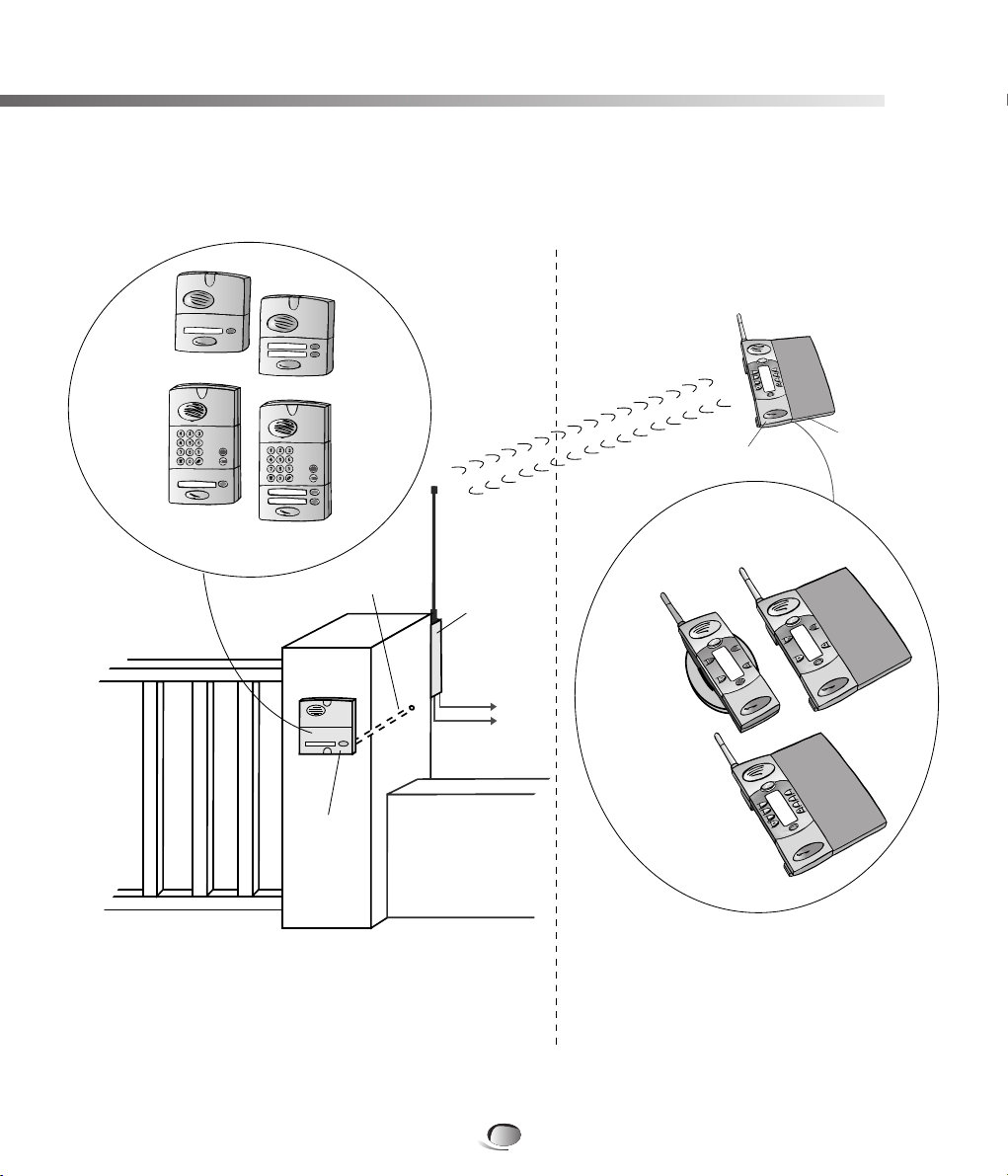
Indoor station
Street Assembly
COMPOSITION OF A DOORPHONE
requires as a minimum
➊+ ➋+ ➌
1 button
caller unit
with keypad
➋

GB
91
Presentation
Every kit comprises as a minimum:
➊
A caller unit on the street side for visitors.
➋
A controller installed on the same pillar (garden side),
ensuring:
• the radio link with the indoor station
• the powering by batteries of the caller unit and controller
• output connections described in R1 and R2.
These products are connected by a cable that passes through
(or around) the pillar.
➌
An indoor station (base and handset) for the reception of calls
and the remote control.
There are 2 models of handset:
• the standard handset (6 keys) allows:
- the control of a door strikes (or electric lock)
- the control of a motorised gate
- the control of lighting (2)
• the multifunction handset (10 keys) allows:
- the control of 2 door strikes (or electric locks) (1)
- the control of 2 motorized gates (1)
- the control of 2 automatic devices
(eg.: motorized garage door…) (2)
- the control of lighting (2)
(1) requires the installation of 2 caller units and controllers
(2) requires a lighting and automatic device controller
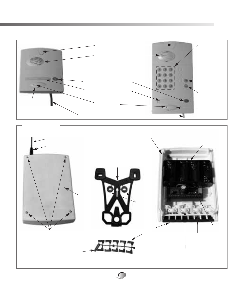
➢ The outdoor units
• The caller units
• The controller
Description
92
Pillar mounting bracket
(on the reverse side of
the controller and locked
in place by a screw located
inside the controller)
Controller base
Captive screw for locking the base
onto the mounting bracket
Telescopic antenna
Antenna sleeve
Cable grommets
(to be detached)
Cable clamp
(do not detach)
Battery housing
Controllers
lid
4 captive screws
for fixing lid
Antenna sleeve
(detachable)
Washers
(detachable)
Push
button
Loudspeaker
NB: The antenna sleeve, cable grommets, cable clamps and cable clamp screws are in the accessory packet.
Personalised name label
(label sheet supplied)*
Keypad for entry
of the access
code preceding
the pedestrian
and vehicle
access
commands
Cable (2.5 m long) for connecting
the caller unit to the controller
Call button
(1 or 2 depending on model)
* Not required
for armoured cover
Microphone
Screw cover
Screw cover*
Screw cover*
Vehicle access
command
button
Pedestrian
access
command
button
GB
93
Description
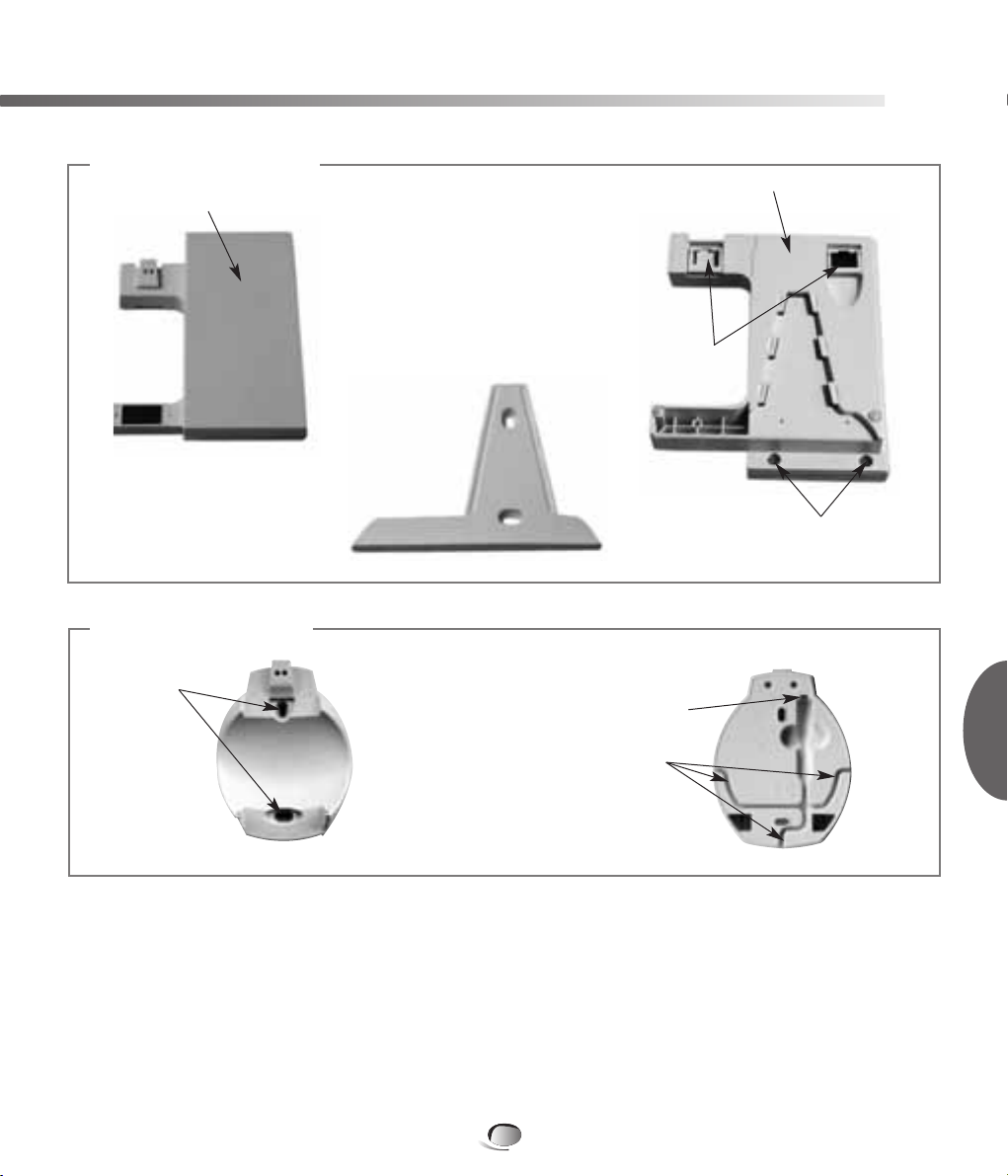
Wall mounting bracket
for internal operator unit
(located on the underside
of the base unit)
Base unit cover
Base unit underside
Captive screws to secure
base unit cover
(2 other screws on top)
Mains
adaptor
cable
channels
Jack socket
Screw cover
Feet
➢ The indoor station (base)
• Battery operated base
• Mains operated base
Description
94
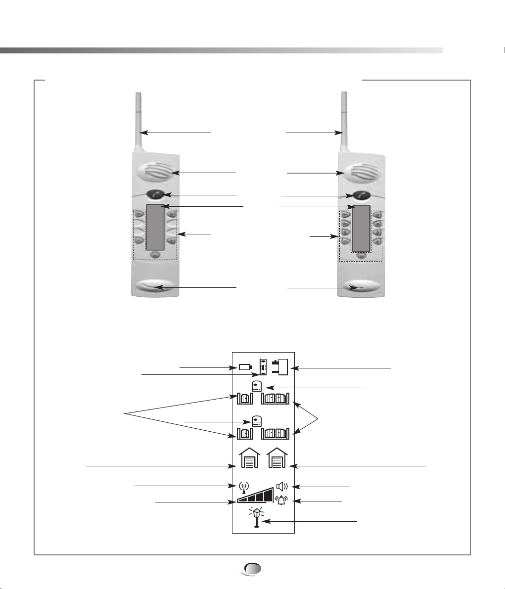
Call button
Control and setting buttons
(according to model)
Display
Telescopic antenna
Loudspeaker
Microphone
2
12
1
Low batteries
Indoor station base unit
Status (open or closed)
of automatic gate
(entry 1 / entry 2)
External caller unit 1
Handset
Status
(open or closed)
of electric door
(entry 1/ entry 2)
Radio reception level
Status (open or closed)
of automatic device 1 (garage door)
Status (open or closed)
of automatic device 2 (garage door)
Level bars
External
Caller Unit 2
Volume level
Ring level
Lighting status
NB: only the indicators specific to your installation will be displayed.
NB: the battery cover is located at the rear of the handset
Display
➢ The indoor station (handset)
• The handset (see user guide for more of details on the handsets keys)
Installing the DoorPhone
95
➢ Installation rules
In order to ensure its weather-tightness:
➀ The technical controller must always be fitted antenna upwards.
➁ Ensure the antenna is tightened correctly.
➂ At the time of installing, always use the cable grommets.
➃ After wiring, ensure the controller’s lid is correctly fitted.
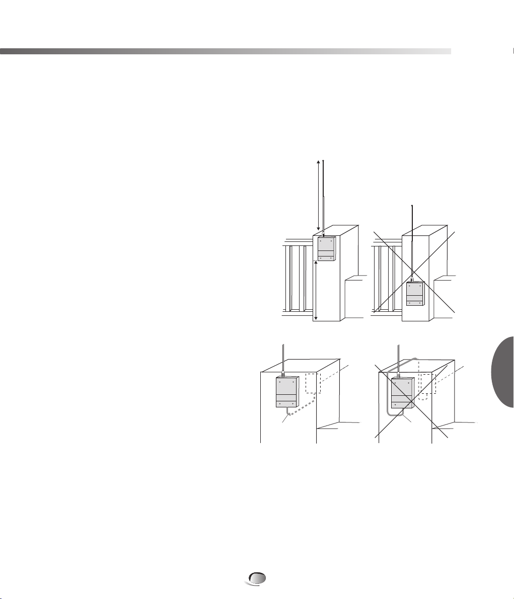
In order to ensure good radio range:
➀ Reserve a free space around the technical
controller's antenna (to a height of about
80 cm).
Clear all dense vegetation in proximity and
ensure it is maintained.
➁ Place the controller as high as possible and
ensure the antenna is clear of the mounting
surface (example: the antenna must not touch
the gate pillars cap).
➂ Limit the presence of obstacle between the
location of the controller and the house where
handsets are installed.
➃ The antenna must be completely extended.
➄ Never run a cable along side of the antenna
(notably the cable between the caller unit
and the technical controller).
Don't coil the cable close to or in the controller,
but cut the surplus.
➅ Also avoid placing the products close to metallic items (metal grilles, enclosures, metallic
gates...) or sources of electromagnetic disturbance:
- for the technical controller: electric meter, high tension electric lines, automatic gate controller,
lighting controller, radio receiver…
- for the handset: television, cordless telephone, domestic electric devices, electricity meter
or panel, computer, hi-fi, lighting controller….
➆ The technical controller must be at least 2 m from the handset location.
NB: if it is necessary to improve the radio range, see the recommendations in the “What to do if?”
section of this guide.
As high
as
possible
caller unit cable caller unit cable
caller
unit
caller
unit
GB
80 cm
 Loading...