

DAITEM 173-21X, 172-21X, 171-21X, 175-21X Installation Manual
(upgraded for e-Nova applications)
GB
72
Summary
1. Introduction.............................. 72
2. Preparation .............................. 74
2.1 Opening the detector ......... 74
2.2 Power supply...................... 74
3. Programming........................... 75
4. Configuration........................... 76
5. Installing the detector............. 78
5.1 Choosing the best place .... 78
5.2 Fixing method..................... 79
5.3 Directing and testing
the detector......................... 81
6. Maintenance............................ 83
6.1 Battery low indication......... 83
6.2 Changing the battery.......... 83
7. Technical data.......................... 84
1. Introduction
The infrared detector is used for protection inside buildings.
Intruders are detected when the infrared radiation associated with
movement varies.
IMPORTANT
• Some functions are only available with versions 2.0.0 or later
(press on the control panel keypad to check
the version).
• The operating differences with former ranges are described in the
compatibility booklet available in the Daitem installers section at
www.daitem.co.uk.
Recommendations
The user must not attempt to access the siren’s internal parts, except areas described in this manual. If the user
does access these parts, the product guarantee will be considered null and void and DAITEM shall not be held
responsible for any problems. Touching the siren’s internal parts and/or electronic components can damage the
product. Furthermore, the siren is designed in such a way that these parts and components do not need to be
accessed for operation or maintenance purposes.
GB
73
0 2 4 6 8 10 12
2,2m
16 18 20 22
14
1
0 5 10
15
2
2
0 5 10
15 20 22
12 m
4
8
0
0 2 4 6 8 10 12 m
2,20
detection zone
(1stinterruption)
detection
zone (
2nd
interruption)
0 1 2 3 4 5 6 7 8 9 10 11 12
2,2m
1
0
2 m
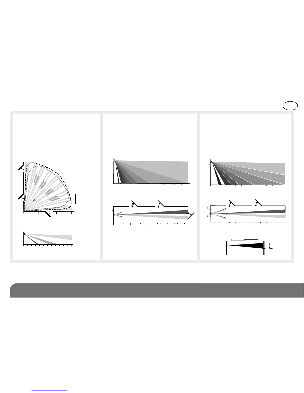
171-21X/175-21X: motion
detector (19 beams, 12 m, 90°) is
designed to protect rooms at risk
(lounge, main bedroom, etc.).
172-21X: corridor detector (9
beams, 22 m, 12°) is designed for
unavoidable passageways, and
can be placed facing the entry
point to be protected.
173-21X: curtain detector (9
beams, 12 m, 8°) is designed for
the protection of large surfaces
(plate glass windows, garage
doors, etc.).
GB
74
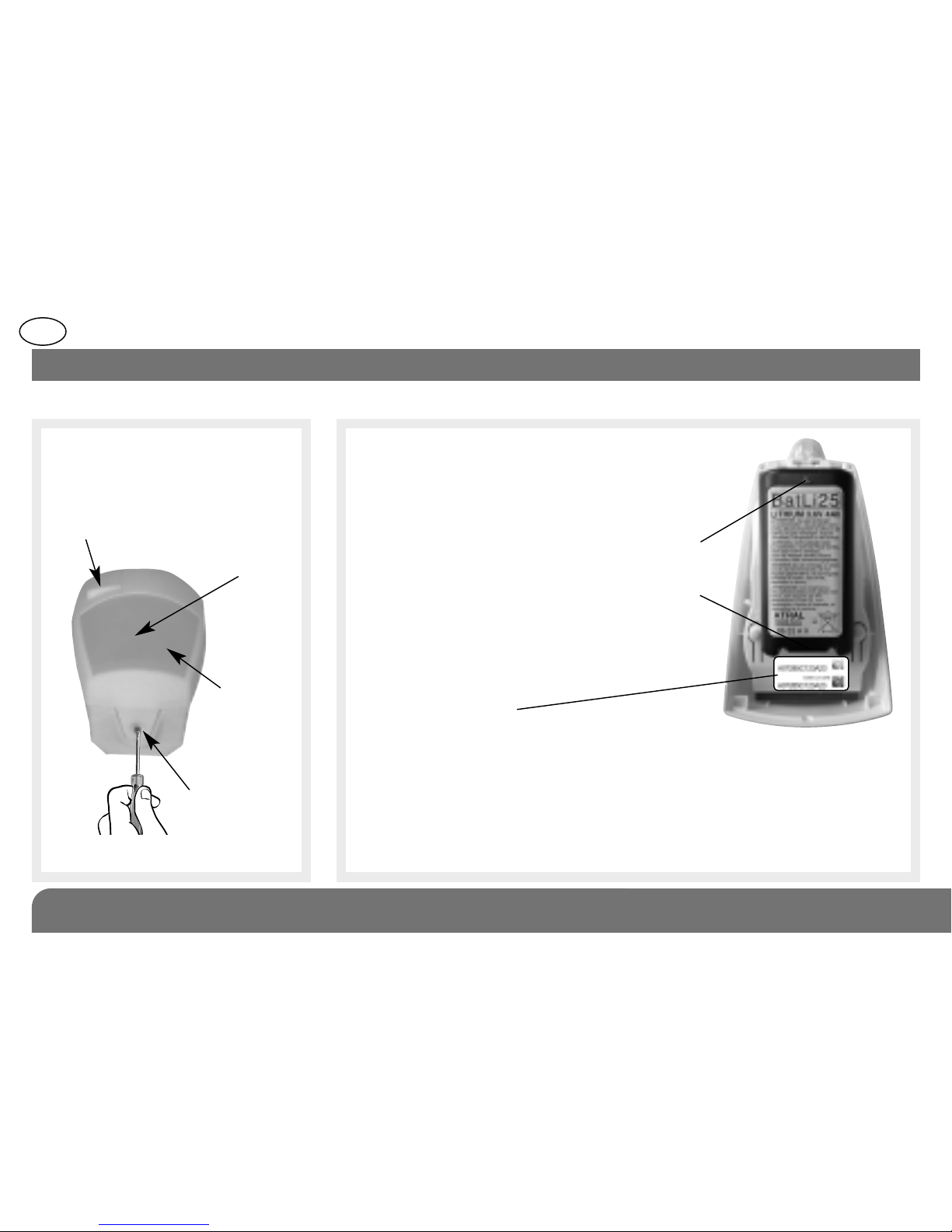
Test key
Test LED
indicator
lamp
behind
lens
Detection
lens
Locking screw
Open the detector casing by
loosening the screws using a
cross-head screwdriver.
2. Preparation
2.1 Opening the detector 2.2 Power supply
Connect the lithium battery pack
according to the arrow.
Alignment arrow
Removal tab
171-21X
171-21X
Guarantee sticker:
Remove the pre-cut part of the sticker
and stick it to the guarantee certificate
in the user manual supplied with the
control panel. If you are adding the siren
to an existing system, use the guarantee
sticker provided with this product.
GB
75
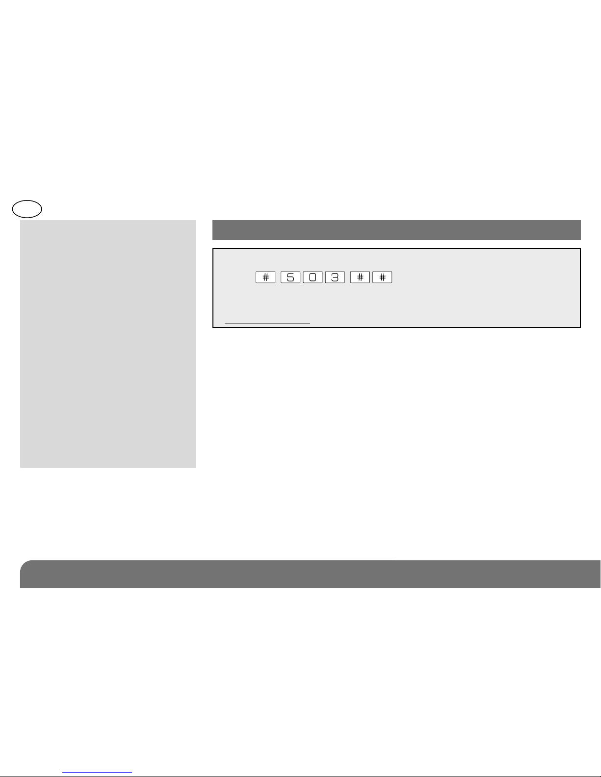
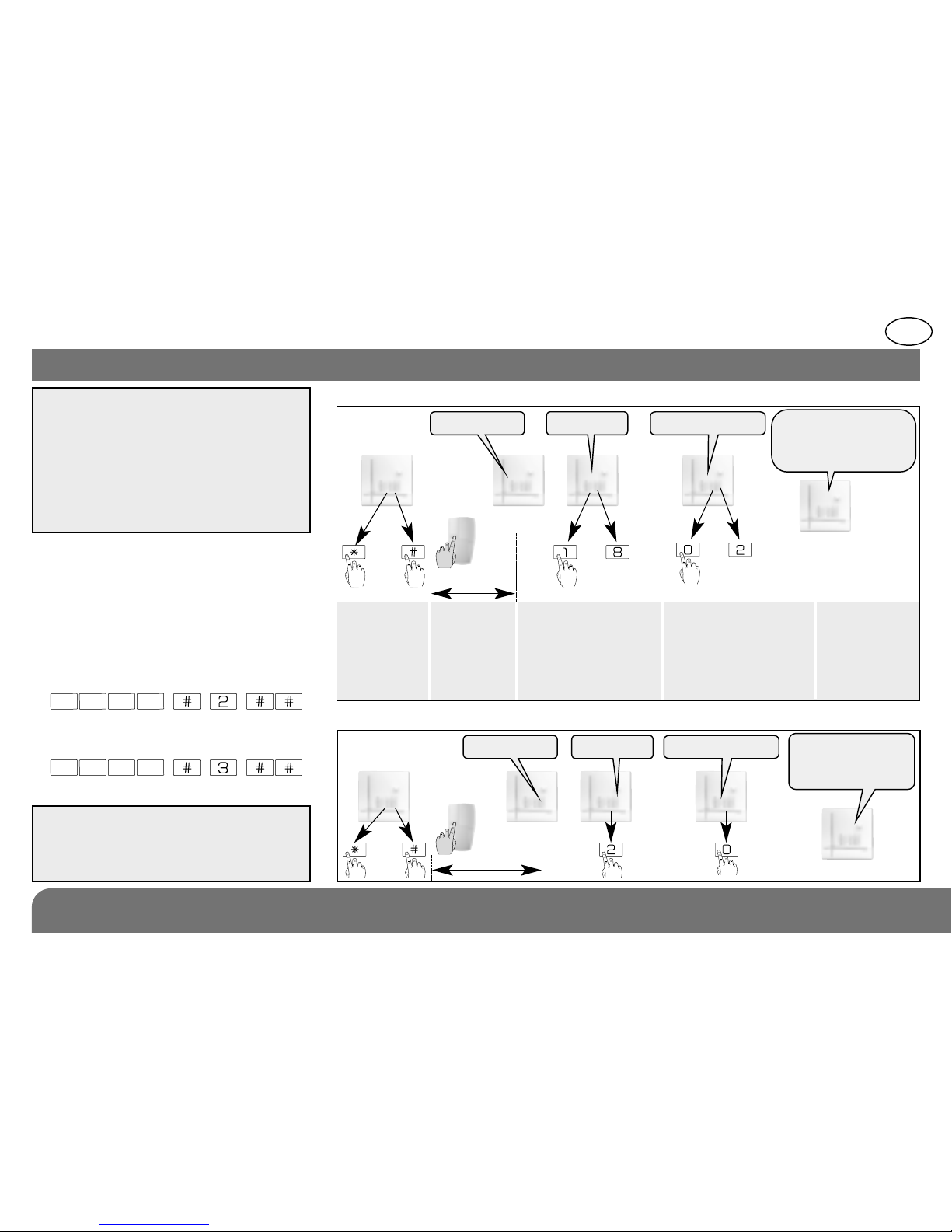
2. Programme the device as follows
3. Programming
Programming enables the detector
to be recognised by the control
panel.
1. To programme the detector the
control panel must be in
installation mode. If it is not, ask
the user to press:
then:
master code
installer code
IMPORTANT: during recognition
programming, the product to be
programmed for use with the control
panel does not need to be placed next
to it. In fact, we recommend you place
the product at a short distance from
the control panel (at least 2 meters
away).
IMPORTANT: the control panel indicates
there is an error by emitting 3 short
beeps. When this happens programming
should be carried out again.
10 s max.
Press
‹
then # on the
control panel
keypad
Press
and hold the
“test” button
until
the control
panel
responds
The control panel waits
for a group to be chosen
(from 1 to 8). Choose the
groups by pressing the
corresponding numeral
on the control panel
keypad
The control panel waits
for the time delay to be
chosen. 0: immediate
1: delayed • 0: combined.
The time delay is chosen
by pressing “0” or “1” on
the control panel keypad
The control
panel gives a
voice message
to confirm
then
to
“détecteur X” “group?” “time delay?”
“beep, detector X,
group Y immediate
(or delayed or
combined)”
Example: programming of 1st detector allocated to Gr. 2 with immediate triggering.
10 s max.
)
)
)
)
then
“detector 1” “group?” “time delay?”
“beep, detector 1
group 2,
immediate”
to
* according to
the model of the
control panel.
*
)
)
)
)
)
GB
76
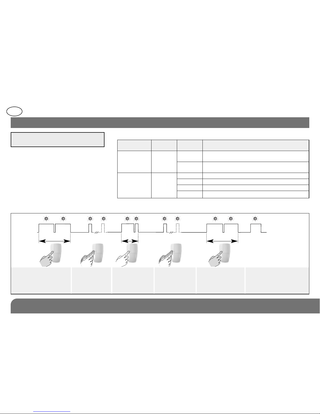
• Follow the configuration sequence described below:
LED indicator
lamp not lit
LED indicator
lamp lit
sequence
about
5 sec.
about 10 sec.
about 2 sec.about 10 sec.
To start the sequence
press and hold the
button until the LED
indicator lamp goes out
Press 1 or 4
times depending
on the required
parameter number
Press and hold
until the LED
indicator lamp
briefly goes out
Press 1 to 4
times depending
on the required
parameter value
To end the sequence
press and hold the
button until the LED
indicator lamp goes
out
LED indicator
lamp lit =
correct
configuration
• Choosing detection sensitivity or alarm level:
Choice Parameter Parameter Technical data
of function n° value
Detection 1 1 1stedge triggering: not recommended
sensitivity for detector 171-21X/175-21X
2 2ndedge triggering (factory setting): recommen-
ded for interior using detector 171-21X/175-21X
Alarm level 4 1 Intrusion (factory setting)
2 Prealarm
3 Deterrence
4 Warning
4. Configuration
IMPORTANT: the casing must be open
when configuring the detector.
 Loading...