

DAITEM 155-21X Installation Manual

Upgraded for e-Nova applications

94
GB
Contents
1. Introduction ................... 94
1.1 How the detector
works......................... 94
1.2 Description................ 95
2. Power supply................. 96
3. Recognition
programming................. 96
4. Installing the detector .. 97
4.1 Choosing the best
place.......................... 97
4.2 Testing the radio
range at the chosen
location ..................... 98
4.3 Fixing the detector
in place...................... 97
4.4 Installing several
detectors
in a network............ 100
5. Testing the detector.... 100
6. Manually disabling
the detector ................. 103
7. Indications ................... 104
7.1 Alerts ...................... 104
7.2 Faults ...................... 104
8. Maintenance................ 105
8.1 Servicing the
detection head........ 105
8.2 Changing
the battery .............. 106
8.3 During DIY work ..... 106
9. Technical data ............. 107
10. User sheet.................. 109
1. Introduction
1.1 How the detector works
The heat detector detects rises in temperature that trigger an
alarm in the following cases:
• when the room temperature rises at an abnormal speed,
or
• when the room temperature reaches between 54°C and
70°C,
(also refer to the table in the Technical Data section).
The heat detector is especially suitable for detecting fires that
spread quickly or at an average speed and in places where an
optical smoke detector cannot be used:
• in a kitchen where there are cooking fumes,
• in uninhabited places where there is a smoky atmosphere or
a lot of dust (e.g. garages).
The heat detector can be:
• used as a stand-alone unit,
• integrated into a Daitem alarm system,
• interconnected in a hard-wired network of up to 40
detectors (heat or smoke).
IMPORTANT: the heat detector is not supposed to replace
smoke or gas detectors to ensure the safety of people
against smoke or gas, and notably in rooms such as
bedrooms, playrooms and other living areas.
IMPORTANT: the heat detector is designed to protect
homes or the private areas of buildings. It is not designed
for public assembly buildings or buildings housing workers.
95
GB
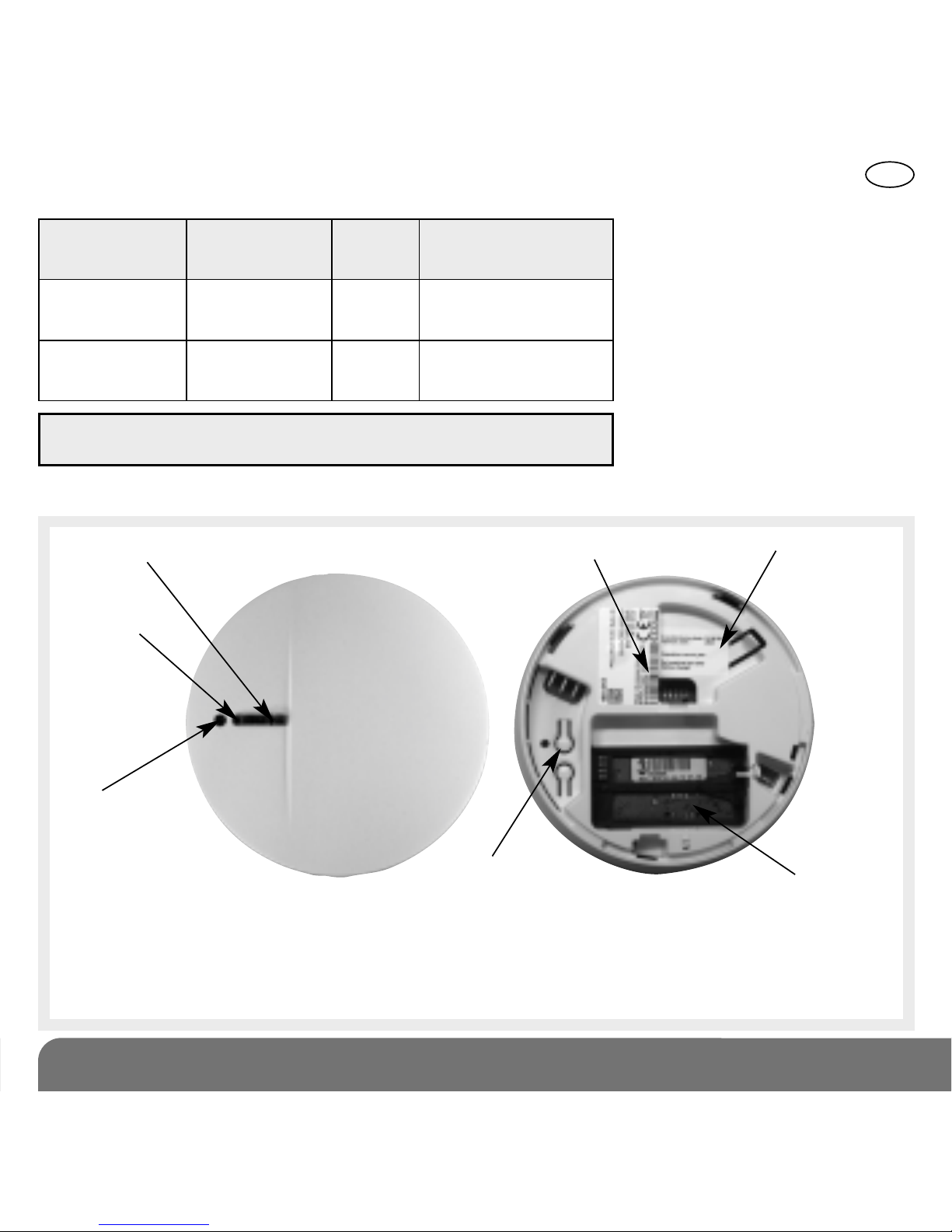
Red LED indicating detector status
Test button
White LED
(safety lighting
when heat is
detected)
Programming
key 0
Lithium
battery
connector
Product
replacement
date
Guarantee sticker
In stand-alone mode, the heat detector responds as follows during the heat detection period:
Guarantee sticker: remove the pre-cut part of the sticker and stick it to the guarantee
certificate in the user manual supplied with the control panel. If you are adding the siren to
an existing system, use the guarantee sticker provided with this product.
Heat detector
transmitting the heat
detection signal
Other hard-wired
interconnected heat
detectors
the LED flashes
quickly
-
a built-in modulated alarm
sounds on a continuous
basis (85 dB(A) at 3m)
a safety
halo lights
up
a safety
halo lights
up
Red LED indicating
detector status
White LED Sounding
1.2 Description
a built-in modulated alarm
sounds on a discontinuous
basis (85 dB(A) at 3m)
When connected to a Daitem
alarm system the detector
responds as follows when it
detects heat:
• triggering of the control
panel and security system
wireless sirens in fire
sounding mode for 5 min.,
• triggering of the telephone
dialler.
IMPORTANT: the heat detector should be replaced every
ten years.
96
GB
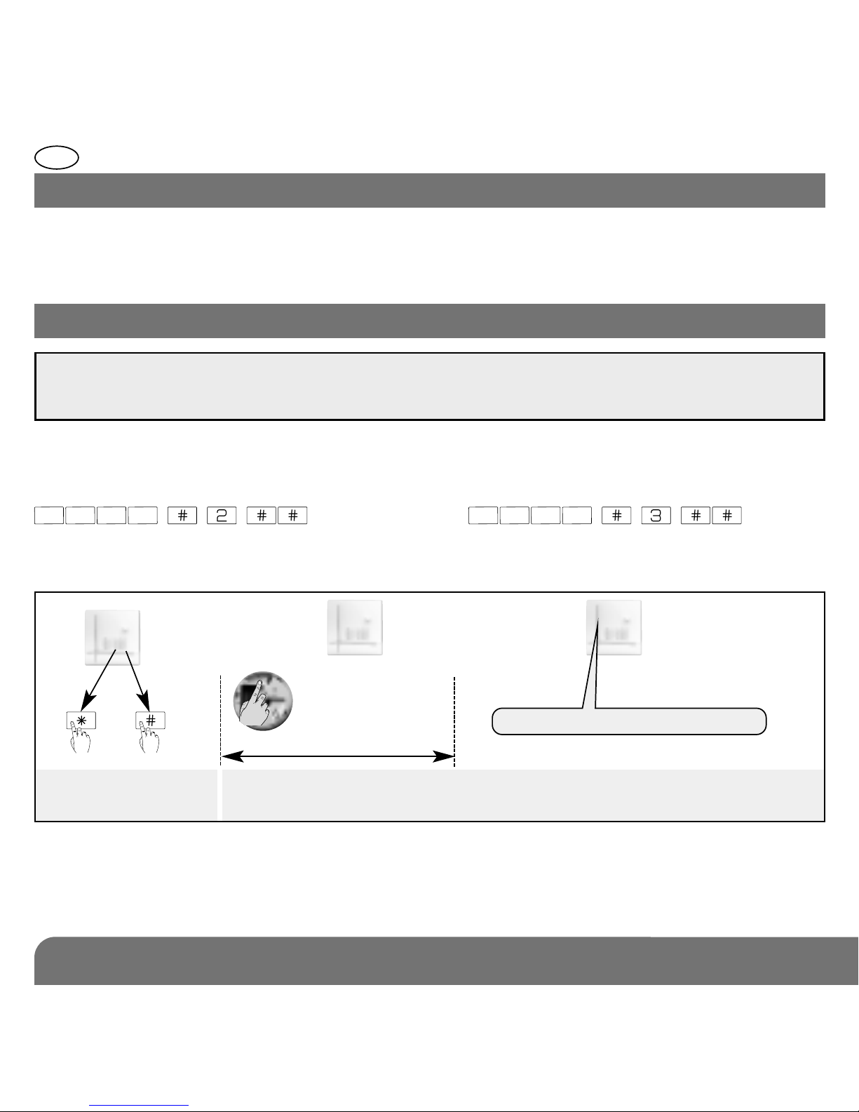
10 s max.
Press *then # on the
control panel keypad
Press & hold the programming key 0 for 10 sec.
until the control panel responds
Carry out the programming sequence described below:
))
)
)
)
“beep, fire detector n° X”
You can record a personalised message to identify the fire detector by voice (see the
control panel installation manual, § on Voice identification message).
Connect the lithium battery making sure it is the right way round.
Ò The red LED flashes for 15 sec, then once every 10 sec to indicate that the detector is
working normally.
2. Power supply
3. Recognition programming
IMPORTANT: during recognition programming, the product to be programmed for use with
the control panel does not need to be placed next to it. In fact, we recommend you place
the product at a short distance from the control panel (at least 2 m away).
Programming enables the heat detector to be recognised by the control panel.
To programme the heat detector, the control panel must be in installation mode. If it is not,
press:
then press:
master code engineer installer code
then

97
GB
4.1 Choosing the best place
The detector must be placed:
• in rooms where there is a risk of fires
spreading quickly or at an average speed,
• in rooms with an aggressive or difficult
environment such as kitchens (cooking
fumes), garages (smoky atmosphere), and
other unoccupied premises or rooms where
there is often a lot of dust,
• preferably at the centre of the ceiling but
positioned so that it is affected by any
abnormal rises in temperature,
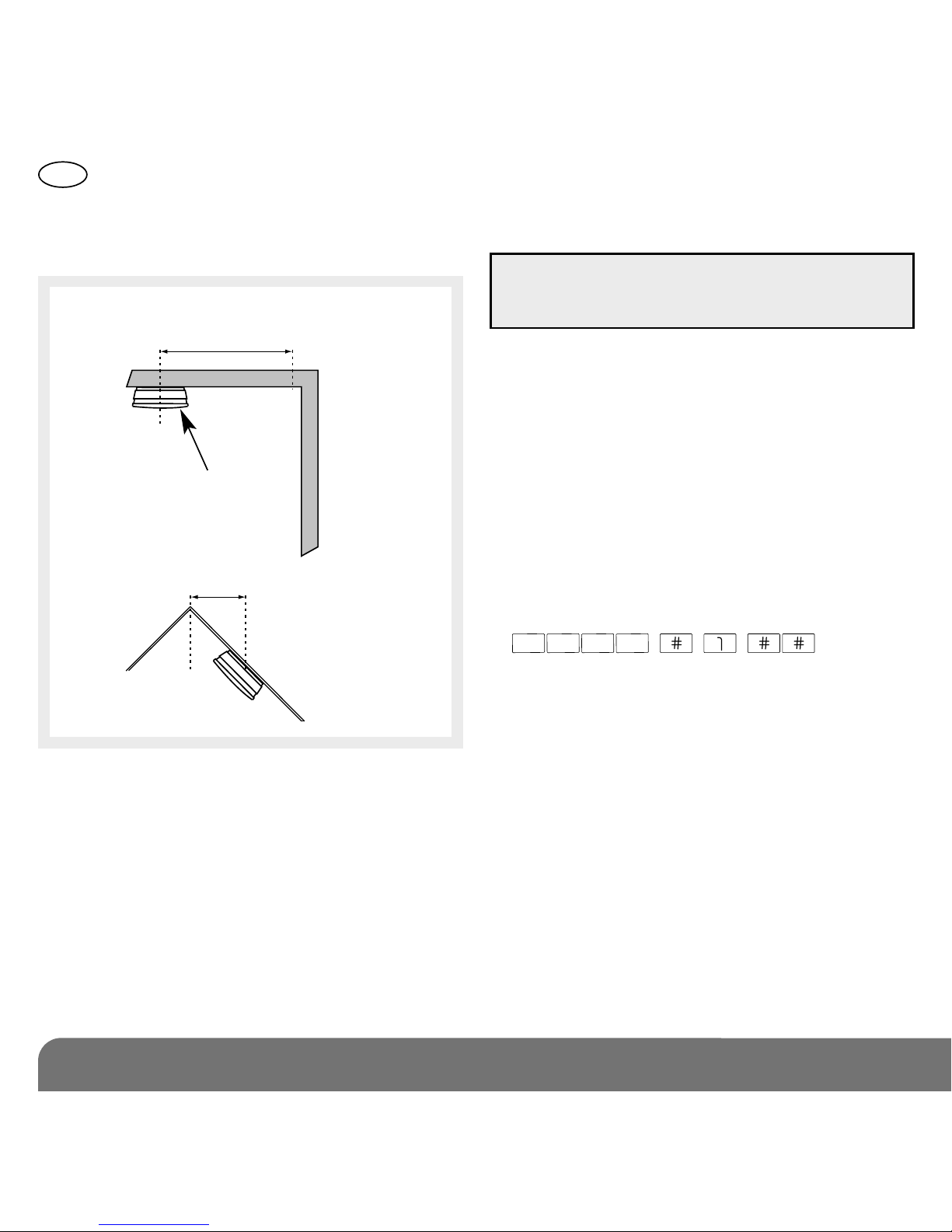
• if the detector cannot be installed in the
centre of the ceiling, install it more than 50
cm away from the corners of the room (Fig.
1 and Fig. 2),
• far away from ventilation grilles that may
spread the heat,
• more than 50 cm away from obstacles
(walls, partitions, beams, etc.),
• at either end of corridors more than 8 m
long,
• far away from potential sources of electrical
interference (electricity meter, metal cabinet,
etc.),
• if it is to be installed on a metal wall, insert a
shim made of non-magnetic material (wood
or plastic).
The detector must not be placed:
• in rooms where a sudden and considerable
rise in the room temperature would cause
untimely triggering of the alarms (e.g.
sudden sunlight),
• in rooms where there is a need to protect
people against smoke or gas(bedrooms,
children’s playrooms, converted cellars,
occupied lofts, emergency exits, etc.),
• near fluorescent tubes,
• directly on a metal surface,
• in a room where the temperature could drop
below -10°C or rise above +55°C, as this
will prevent the detector from operating
properly,
4. Installing the detector
Make sure there is a distance of at least 2 m between each product, except between two
detectors.
IMPORTANT: the heat detector is not supposed to replace smoke or gas detectors to
ensure the safety of people against smoke or gas, and notably in rooms such as bedrooms,
playrooms and other living areas. The heat detector is designed to detect fires in places
where an optical smoke detector cannot be used. For basic protection, a smoke detector
should be installed in at least each bedroom (refer to smoke detector manual).
98
GB
4.2 Testing the radio range
at the chosen location
1. Hold down the detector programming key
0 or the test button until the built-in
sounding can be heard:
• correct: the control panel confirms the
radio link with a voice message “beep,
fire detector n° X”,
• incorrect: if there is no voice message,
move the heat detector closer to the
control panel.le.
2. Put the control panel back in user mode by
pressing:
• in rooms where the relative humidity might
rise above 95% (without condensation),
• close to heating, cooling or air vents.
Mounting examples:
Recommended
location
d > 50 cm
plafond
Fig. 1
d > 50 cm
Fig. 2
IMPORTANT: the control panel must be in
installation mode to perform this test (see
Recognition programming).
engineer installer code
 Loading...