

DAITEM 145-21X Installation Manual
Outdoor motion detector 2 x 12 m
145-21X
INSTALLATION MANUAL
GB
67
Summary
1. Introduction .................................... ........... 67
2. Preparation ..................................... ........... 69
2.1 Opening the detector........................... . 69
2.2 Power supply ................................... ..... 69
3. Programming..................................... ........ 70
4. Configuration.................................... ......... 71
5. Installation precautions........................ .... 72
6. Installation.................................... .............. 73
6.1 Testing the radio link......................... .... 73
6.2 Fixing......................................... ............ 73
7. Configuration and adjustments
of detection....................................... ......... 74
7.1 Range of detection ............................. .. 74
7.2 Horizontal adjustment
of the detection angle........................... 76
7.3 Adjustment of the sensitivity ................ 77
7.4 Adjustment of the operational
options ............................................ ...... 77
8. Operating test.................................. .......... 78
8.1 Detection zone test............................ ... 78
8.2 Real test...................................... .......... 78
9. Maintenance..................................... ......... 78
9.1 Fault indication............................... ....... 78
9.2 Changing the battery........................... . 78
10. Technical data ................................. ........ 79
The 2 x 12 m external motion detector has been spec ially designed to detect intruders before
they have a chance to break in by monitoring the ar ea outside the protected site.
Because both detection systems operate on either si de of the detector and detection can be
adjusted to provide narrow 4 to 24 m protection (2 x 12 m on each side), this is the ideal
product for protecting a façade.
Its immunity to false alarms caused by sunlight or car headlights is backed up by its highly
reliable pet-tolerant detection system (both detect ion beams have to be broken in order to
trigger a prealarm or alarm). Its performance is fu rther enhanced by a temperature
compensation system that automatically adjusts and increases detection sensitivity when the
outside temperature comes close to that of a human being (35°C - 37°C).
1. Introduction
Recommendations
The user must not attempt to access the siren’s int ernal parts, except areas described in this
manual. If the user does access these parts, the pr oduct guarantee will be considered null
and void and DAITEM shall not be held responsible f or any problems. Touching the siren’s
internal parts and/or electronic components can dam age the product. Furthermore, the siren
is designed in such a way that these parts and comp onents do not need to be accessed for
operation or maintenance purposes.
IMPORTANT
• Some functions are only available with control pa nel version 2.0.0 or later
(enter ) on the control panel keypad to check the v ersion).
• Operating differences with respect to former rang es are described in the compatibility booklet
available in the Daitem Installers section at www.d aitem.co.uk .
GB
68
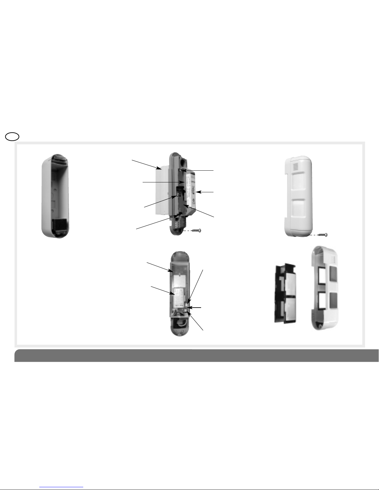
Top pyro sensor
Bottom pyro sensor
Switch for sensitivity
options
Range detection
switch
Led Indicator
Locking screwAnti-tamper
mechanism
Radio box
Radio board
Test key
Lithium battery
connector
Indicator lamp
for programming
Lens
support
Lithium battery
Locking screw x 2
Back box Detector module
Detection unit with radio box open
Cover
Cover
GB
69
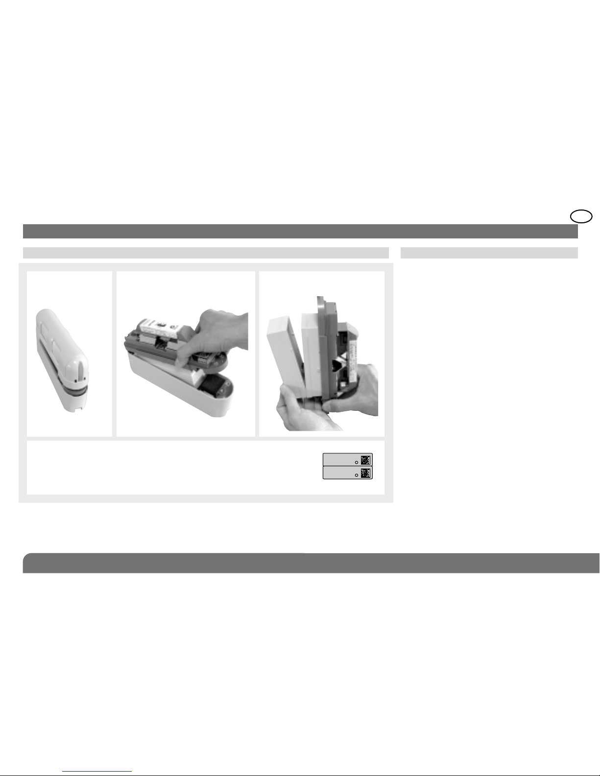
2. Preparation
Connect the battery. When switched on, the
detector runs a self-test. If the self-test is:
• correct, the LED indicator lamp lights up for
2 sec.,
• incorrect, the LED indicator lamp flashes
every 5 sec.
d
d
1. Remove the
cover.
2. Remove the back box.
2.1 Opening 2.2 Power supply
3. Open the radio box.
Guarantee sticker: remove the pre-cut part of the sticker and stick
it to the guarantee certificate in the user manual s upplied with the
control panel. If you are adding to an existing sys tem, use the
guarantee certificate supplied with this product.
145-21X
A1142A047879
Coller sur certif
145-21X
A1142A047879
Coller sur certif
d
GB
70
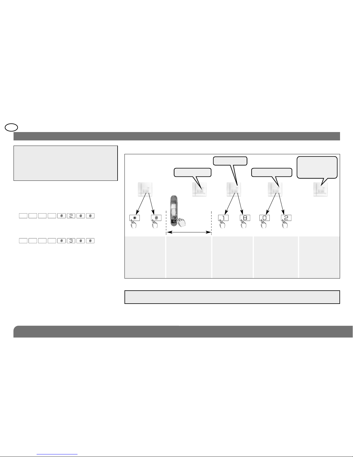
2. Programme the detector as follows:
IMPORTANT: during recognition
programming, the product to be programmed
for use with the control panel does not need
to be placed next to it. In fact, we recommend
you place the product at a short distance
from the control panel (at least 2 m away).
3. Programming
*
1. Change the control panel to installation
mode if necessary by pressing the
following sequence on the control panel
keypad or the hardwired control interface
then:
IMPORTANT: the control panel indicates there is an e rror by emitting 3 short beeps.
When this happens programming should be carried out again.
master code
engineer
installer code
10 s max.
Press and hold the
“test” button until
the control panel
responds
The control panel
waits for a group
to be chosen (from
1 to 8)*. Choose
the groups by
pressing the
corresponding
numeral on the
control panel keypad
Select the time delay:
0: immediate
1: delayed
2: combined
Use the control panel
keypad to do this.
The control panel
gives a voice
message to
confirm
Press *then #
on the control
panel keypad
)
)
))
)
* Depends on the type of the control panel
then to to
“group?”
“time delay?”“detector X”
“beep, detector X,
group Y, immediate
(or delayed
or combined)”
GB
71
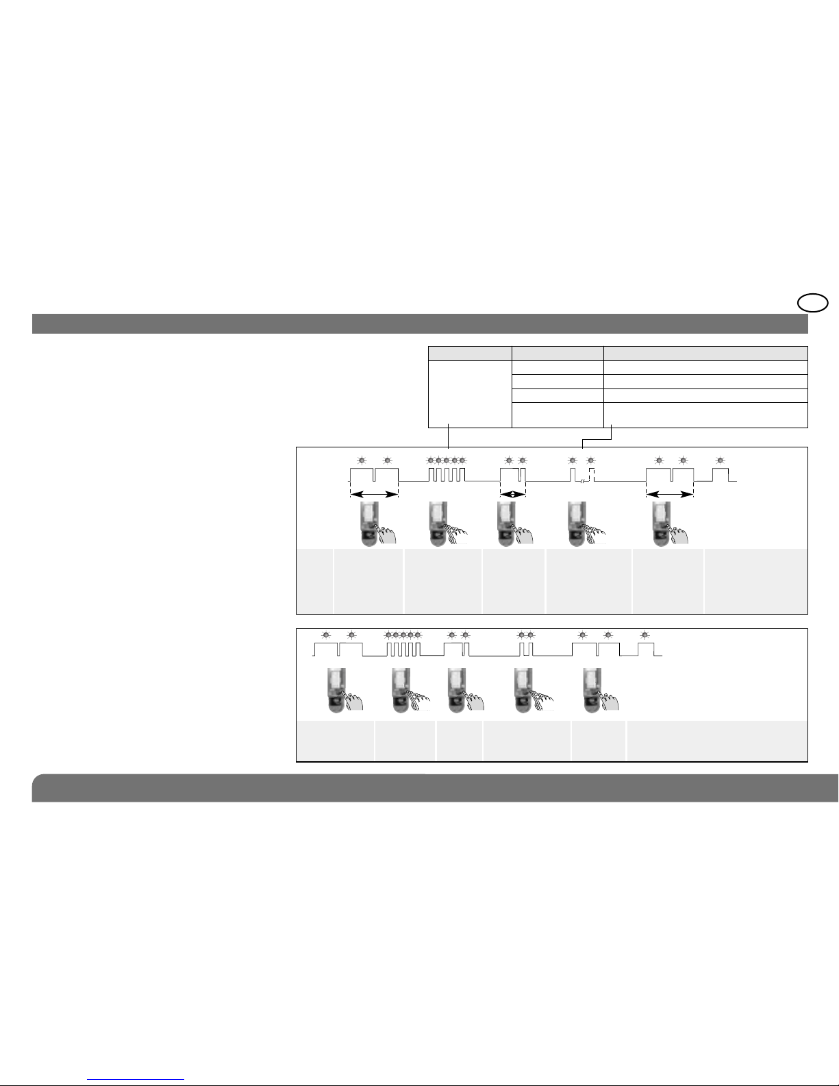
In factory configuration, the movement
detector is configured in deterrence (for the
reactions of the system see the control panel
installation guide). It is possible to modify the
level of alarm using the following sequence
of parameter setting:
Sequence of
parameter setting
Configuration example: setting the
detector for an alarm level when a prealarm
is triggered: Parameter n° 5, Parameter value
2.
??
4. Configuration
sequence
about
5 sec.
about 10 sec.
about
2 sec.
about 10 sec.
To start the
sequence
press and
hold the
button until the
LED indicator
lamp goes out
Press 5 times
depending
on the required
parameter
number
Press and
hold until the
LED
indicator
lamp briefly
goes out
Press 1 to 4
times depending
on the required
parameter value
To end the
sequence press
and hold the
button until the
LED indicator
lamp goes out
LED indicator
lamp lit =
correct
configuration
{
{
Start Press 5 times
to select
the alarm
level
Press
once to
accept
selection
Press 2 times
to select
the preal
level
End
5 2
about
2 sec.
Indicator lamp
for
programming it
Indicator lamp
for programming
not lit
Parameter n° Alarm level Parameter value
5 Intrusion 1
Prealarm 2
Deterrence 3 (factory setting)
Warning 4 (the feature is available usingn eclosntrol pa
with 2.0.0 version software or later)
 Loading...