

DAITEM 144-21X Installation Manual
Upgraded for e-Nova applications
52
GB
The special animal immune external movement detector monitors the inside or the
outside of buildings and distinguishes between humans and animals.
It is equipped with two sets of detection beams (higher and lower) which must be broken
simultaneously to activate a pre-alarm or a full alarm. Its detection range can be
adjusted, reducing false alarms due to unwanted detections (cars, people or animals
outside the desired protection area).
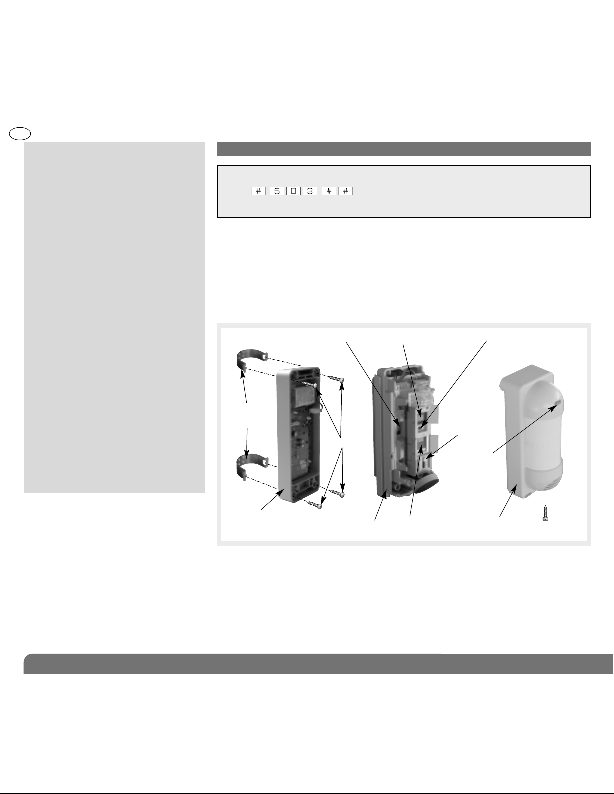
Description
Summary
1. Introduction ............................................... 52
2. Preparation ................................................ 53
2.1 Opening the detector............................ 53
2.2 Power supply........................................ 53
3. Programming............................................. 54
4. Configuration............................................. 55
5. Installation precautions............................ 55
6. Installation.................................................. 56
6.1 Testing the radio link............................. 56
6.2 Wall fixing.............................................. 56
6.3 Pole fixing.............................................. 56
7. Configuration and adjustments
of detection................................................ 57
7.1 Range of detection ............................... 57
7.2 Horizontal orientation............................ 57
7.3 Mask a zone.......................................... 58
7.4 Adjustment of the sensitivity ................ 58
7.5 Adjustment of the operational
options .................................................. 58
8. Operating test............................................ 59
9. Maintenance.............................................. 60
9.1 Fault indication...................................... 60
9.2 Changing the battery ............................ 60
10. Technical data ......................................... 61
1. Introduction
Detector module
Top pyro sensor
Bottom pyro sensor
Switch for sensitivity optionsDip-switch for operational
options
Range
detection
switch
Cover
Led
Indicator
Locking screw
Back box
Clamps
for
post
Screws
IMPORTANT
• Some functions are only available with control panel version 2.0.0 or later
(enter ) on the control panel keypad to check the version).
• Operating differences with respect to former ranges are described in the compatibility booklet
available in the Daitem Installers section at www.daitem.co.uk.
Recommendations
The user must not attempt to access the detector’s internal parts, except areas described in this manual. If the user does access these
parts, the product guarantee will be considered null and void and DAITEM shall not be held responsible for any problems. Touching
the detector’s internal parts and/or electronic components can damage the product. Furthermore, the detector is designed in such a
way that these parts and components do not need to be accessed for operation or maintenance purposes.
53
GB
Connect the battery.
When switched on, the detector runs a self-test.
If the self-test is:
• correct, the LED indicator lamp lights up for 2 sec.,
• incorrect, the LED indicator lamp flashes every 5 sec.
d
d
.
.
2. Preparation
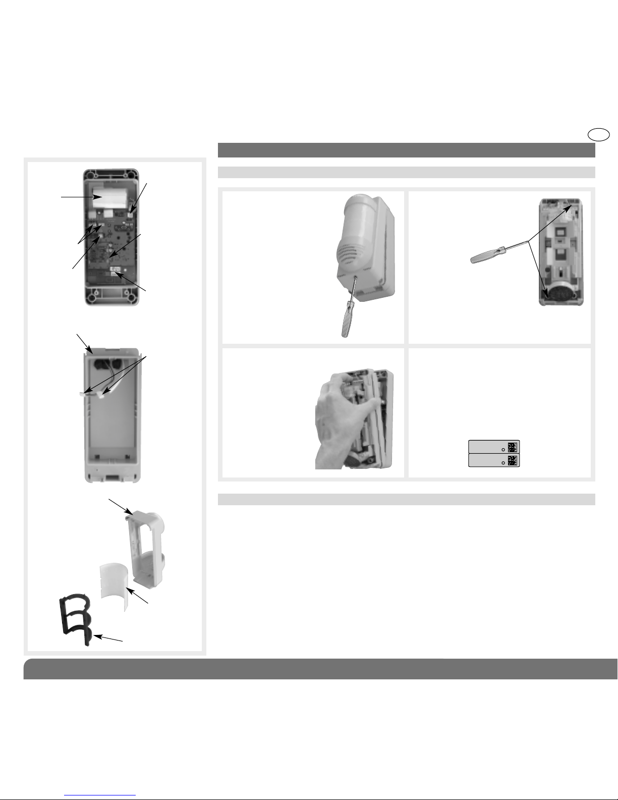
2.1 Opening the detector
2.2 Power supply
Detector module
Cover
Radio
board
Test key
Lithium battery
connector
Indicator lamp
for programming
Connector
for detection
module
Connecting
cables for
radio board
and detector
module
Lens support
Detection lens
Lithium
battery
1. Undo the screw with
a phillips screwdriver
and remove the
cover.
2. Unscrew the
detector module
fixing screw.
3. Remove the back
box.
Description (continued)
Guarantee sticker: remove the pre-
cut part of the sticker and stick it to
the guarantee certificate in the user
manual supplied with the control
panel. If you are adding to an existing
system, use the guarantee certificate
supplied with this product.
144-21X
A1142A047879
Coller sur certif
144-21X
A1142A047879
Coller sur certif
54
GB
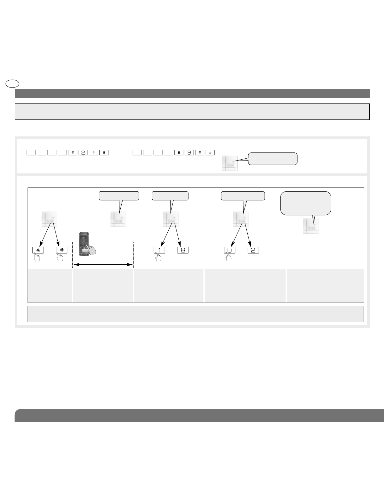
3. Programming
IMPORTANT: the device does not need to be placed close to the control panel for recognition programming. In fact, we advise you to
move the product at least 2 metres away from the control panel.
This operation allows the control panel to recognise the detector.
2. Proceed as follows for recognition programming:
1. For detector recognition programming, the control panel must be in installation mode. If it is not, ask the user to enter:
then
IMPORTANT: the control panel issues three short beeps to indicate a programming error. When this happens, programming must
be performed again from the beginning.
Press *then # on
the control panel
keypad.
Press and hold the “test”
button until the control
panel responds.
Select the group from 1 to
8*. Use the control panel
keypad to do this.
Select the time delay:
0: immediate
1: delayed
2: combined
Use the control panel
keypad to do this.
The control panel
issues a voice
message to confirm
detector recognition
programming.
then to
))
)
)
)
10 s max.
“detector X” “group ?” “time delay?”
*
to
* depending on the type
of control panel
master code (factory: 0000) installer code (factory: 1111)
“beep, detector X,
group Y, immediate
(or delayed
or combined)”
“beep, installation
mode”
55
GB
In factory configuration, the movement detector is configured in
Deterrence (for the reactions of the system see the control panel
installation guide). It is possible to modify the level of alarm using
the following sequence of parameter setting:
Parameter n° Alarm level Parameter value
4 Intrusion 1
Prealarm 2
Deterrence 3 (factory setting)
Warning 4 (the feature is available using control panels
with 2.0.0 version software or later)
Sequence of
parameter setting
Indicator
lamp for
programming
not lit
Indicator
lamp for
programming lit
sequence
about
10 sec.
about
5 sec.
about
10 sec.
about
2 sec.
To start
the sequence
press and hold
the button
until the LED
indicator lamp
goes out
Press 4 times
depending
on the required
parameter
number
Press and
hold until
the LED
indicator
lamp
briefly
goes out
Press
1 to 4 times
depending
on the
required
parameter
value
To end
the sequence
press and
hold the
button until
the LED
indicator
lamp goes
out
LED
indicator
lamp lit
=
correct
confi -
guration
Configuration example: setting the detector for an alarm level
when a prealarm is triggered: parameter n° 4, parameter value 2.
4 2
2 s.
env.
Start
Press 4 times
to select
the alarm
level
Press
once to
accept
selection
Press 2 times
to select
the prealarm
level
End
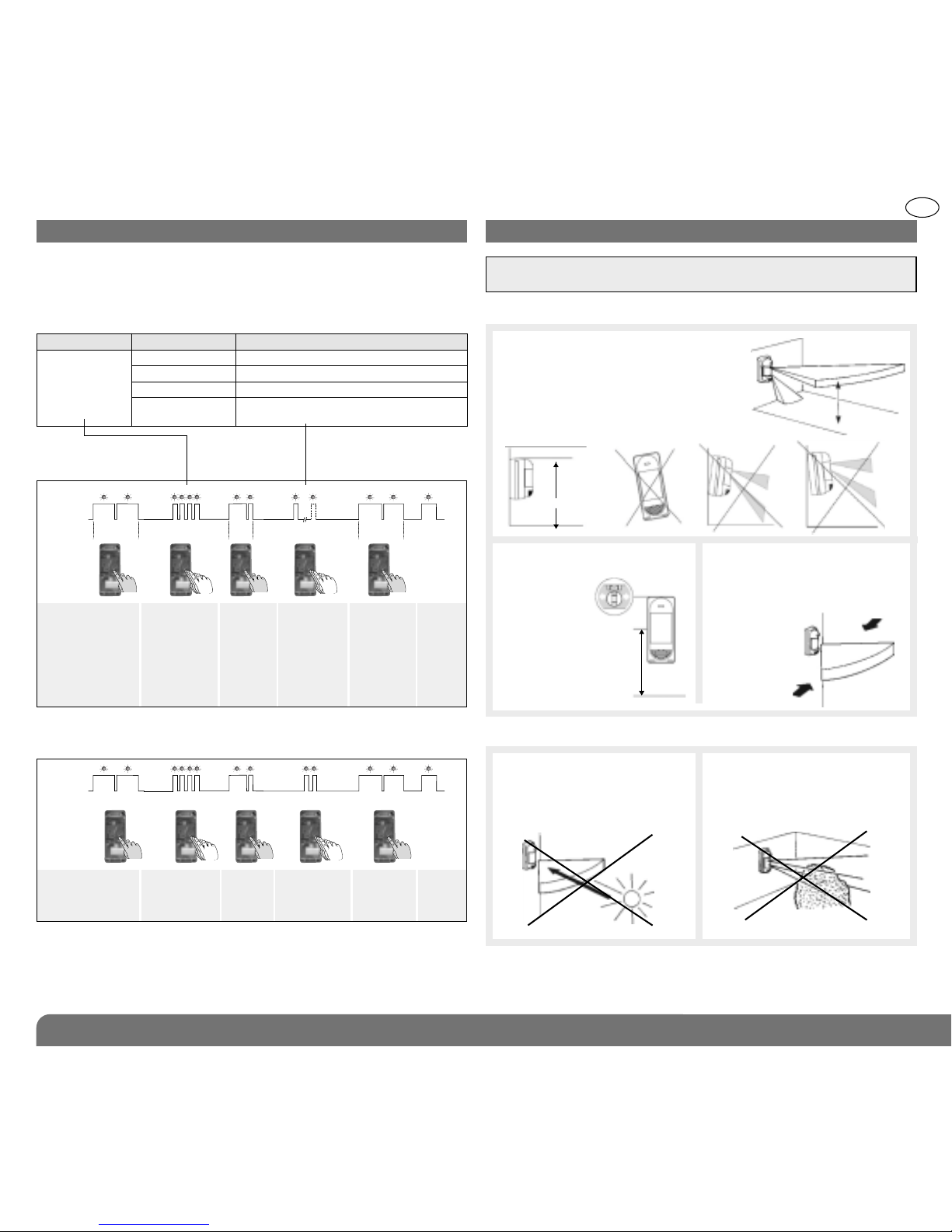
The motion detector must be placed:
The motion detector must not be placed:
Directly on to a metal wall or close to sources of interference
(electricity meters, etc.) or ventilation such as air-conditioning
grilles.
parallel
0.8 m < H < 1.2 m
With an installation height
from 0.8 to
1.2 m high.
Perpendicular to the ground, so that
the zone of higher detection is
parallel to the ground.
If the detector is tilted compared
to the ground, the reliability
of operation can be reduced.
4. Configuration 5. Installation precautions
{
{
IMPORTANT: make sure there is a distance of at least 2 meters between
each product, except between two detectors.
parallel
In direction of moving objects
(branches, bushes, flags,
etc.).
In an area likely to receive
direct sunlight or a very
powerful light source.
By adjusting the zone of
detection so that the objects
or people moving “cross”
the zone of
detection.
 Loading...