

5-8
INM12006 – MOOMONITOR + V3.0
Copyright Dairymaster 2015
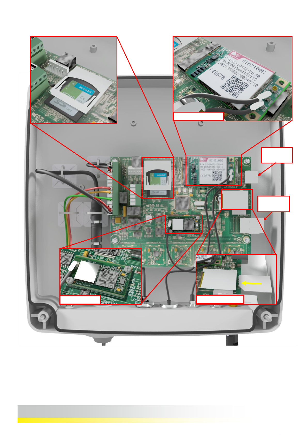
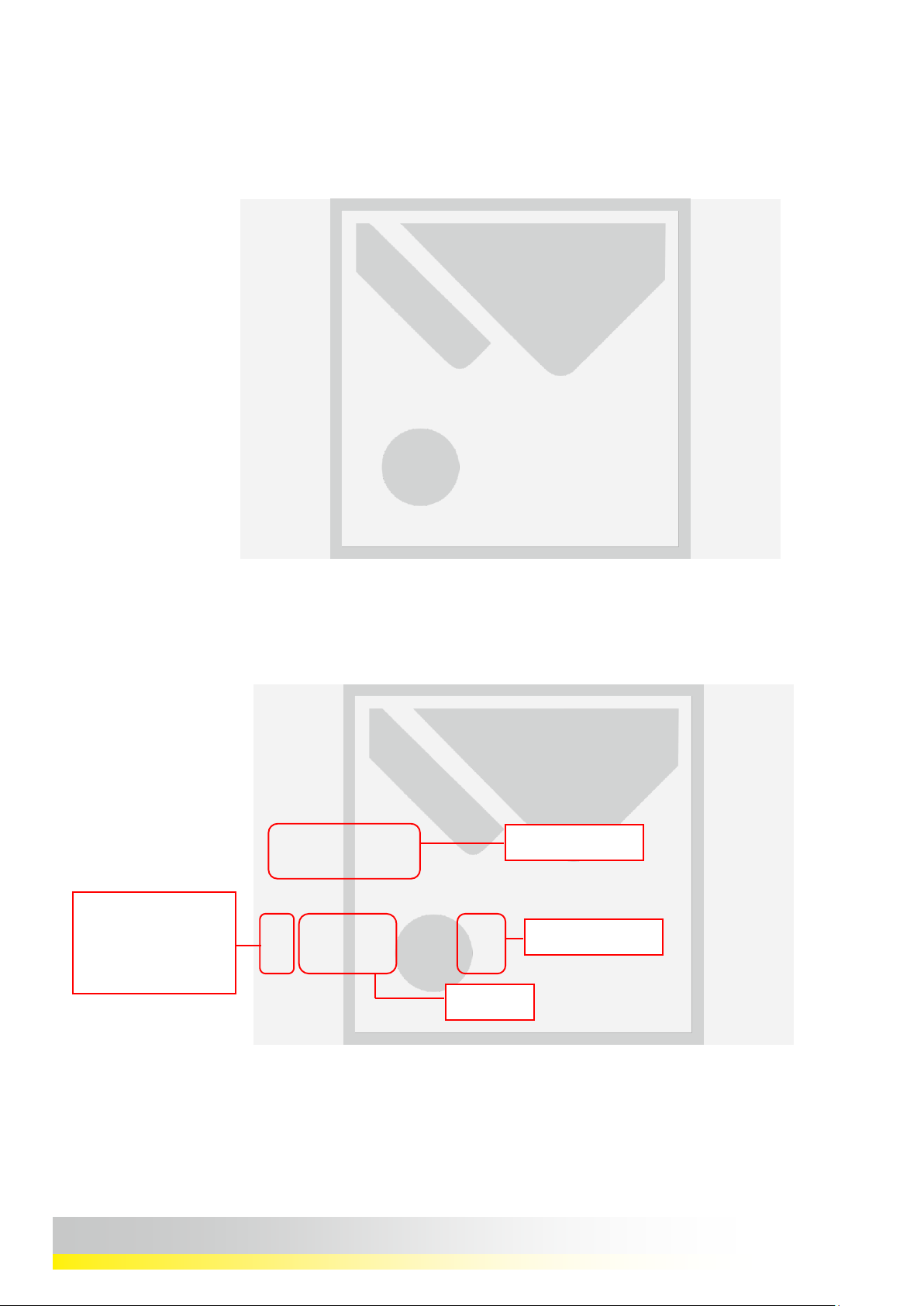
Figure 36 – Base Station PCB Components
SD Card Module
GPS GSM Module
WI-FI Module
Sim card Module
USB
Connector
CAT 6
Connection

5-9
INM12006 – MOOMONITOR + V3.0
Copyright Dairymaster 2015
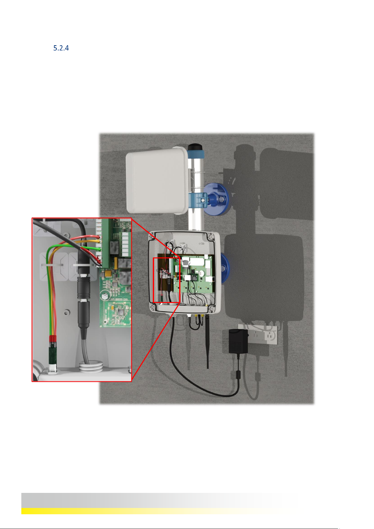
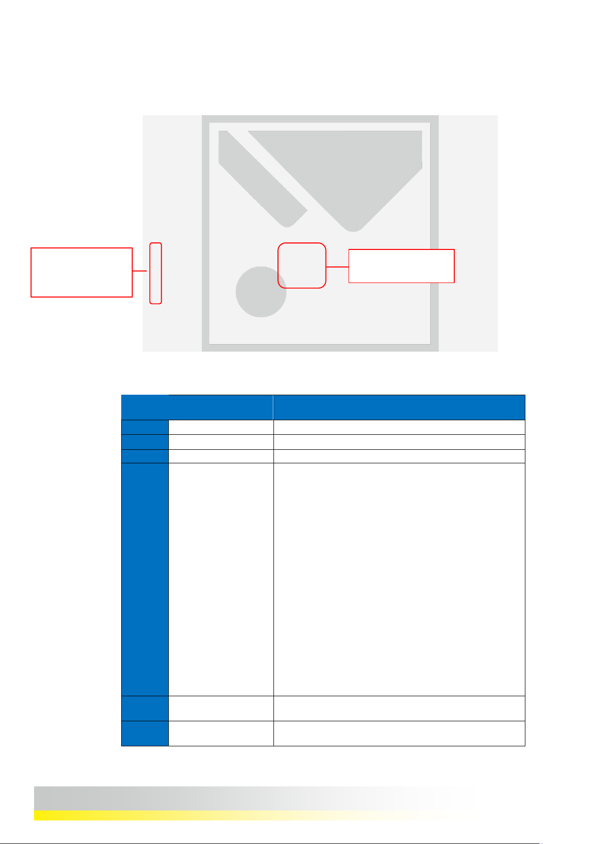
CAT 6 Connection to Basestation
Each Basestation is also fitted with a CAT 6 connection. In areas where WI-FI is
subject to disruption due to signal interference or other contributing factor the
installer may wish to install a CAT 6 cable connection onto the PCB board of the
base station.
Notes:
Dairymaster can provide a CAT 6 cable if require. This will need to be ordered
separately through the following part codes:
Description
Part Code
CAT6 LEAD (5M)
10401735
CAT6 LEAD (20M)
10401743
CAT6 LEAD (40M)
10401750
CAT 6 cable connected
into the connection
into the Basestation
Figure 37 - CAT 6 cable connected into the Basestation

5-10
INM12006 – MOOMONITOR + V3.0
Copyright Dairymaster 2015
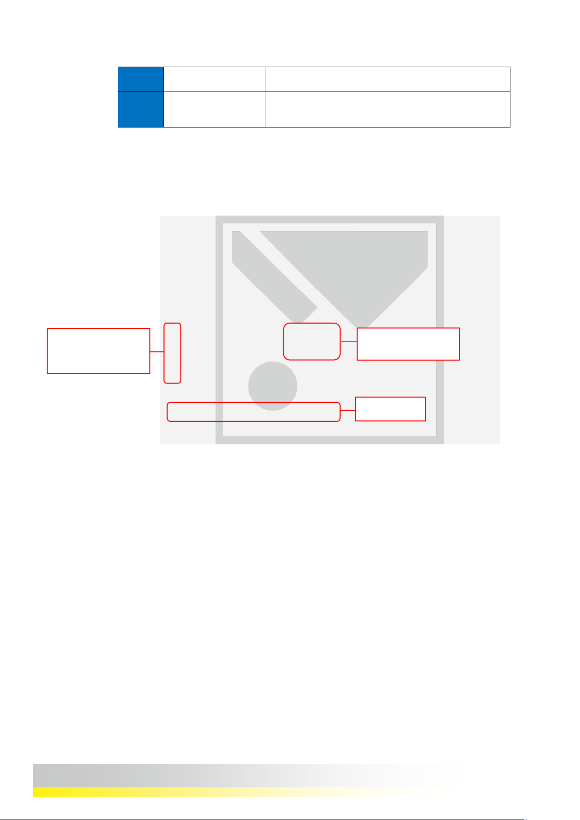
Basestation ISM Antenna Radio Frequencies
Each Base Station has a 5-way radio by default to allow for a wider spectrum to be
accommodated on site in the event of interference from an outside radio source
and selection of each of the radio channels is region dependant.
Figure 38 - Five Channel Radio is located on the Base Station PCB
Five Radio channels
Important Notes
There are five radio channels on the MooMonitor + PCB. These channels are
specific to the region of installation and are currently as follows:
ISM Radio Channel 3 = European Installation (countries within the EU &
UK).
ISM Radio Channel 4 = American Installation (Installations within the
USA).
ISM Radio Channel 5 = Australia & New Zealand.
Currently Radio channels 1 & 2 are currently not in use and should not be
connected to the ISM antenna unless specifically instructed to do so by
Dairymaster.
5-11
INM12006 – MOOMONITOR + V3.0
Copyright Dairymaster 2015
Connecting the 12V DC Power Supply
The Base Station is provided with a 12V DC adapter which serves as the power
supply to the unit. This makes the unit exceptionally easy for the installer to fit.
The client’s electrical contractor must provide an electrical connection as
discussed in section 5.1
Route the electrical cable from the 12v DC adapter into the base station using the
large electrical gland at the base of the unit.
Figure 39 - View of the Electrical connection to the Base Station
using the 12V DC Adapter
5-12
INM12006 – MOOMONITOR + V3.0
Copyright Dairymaster 2015
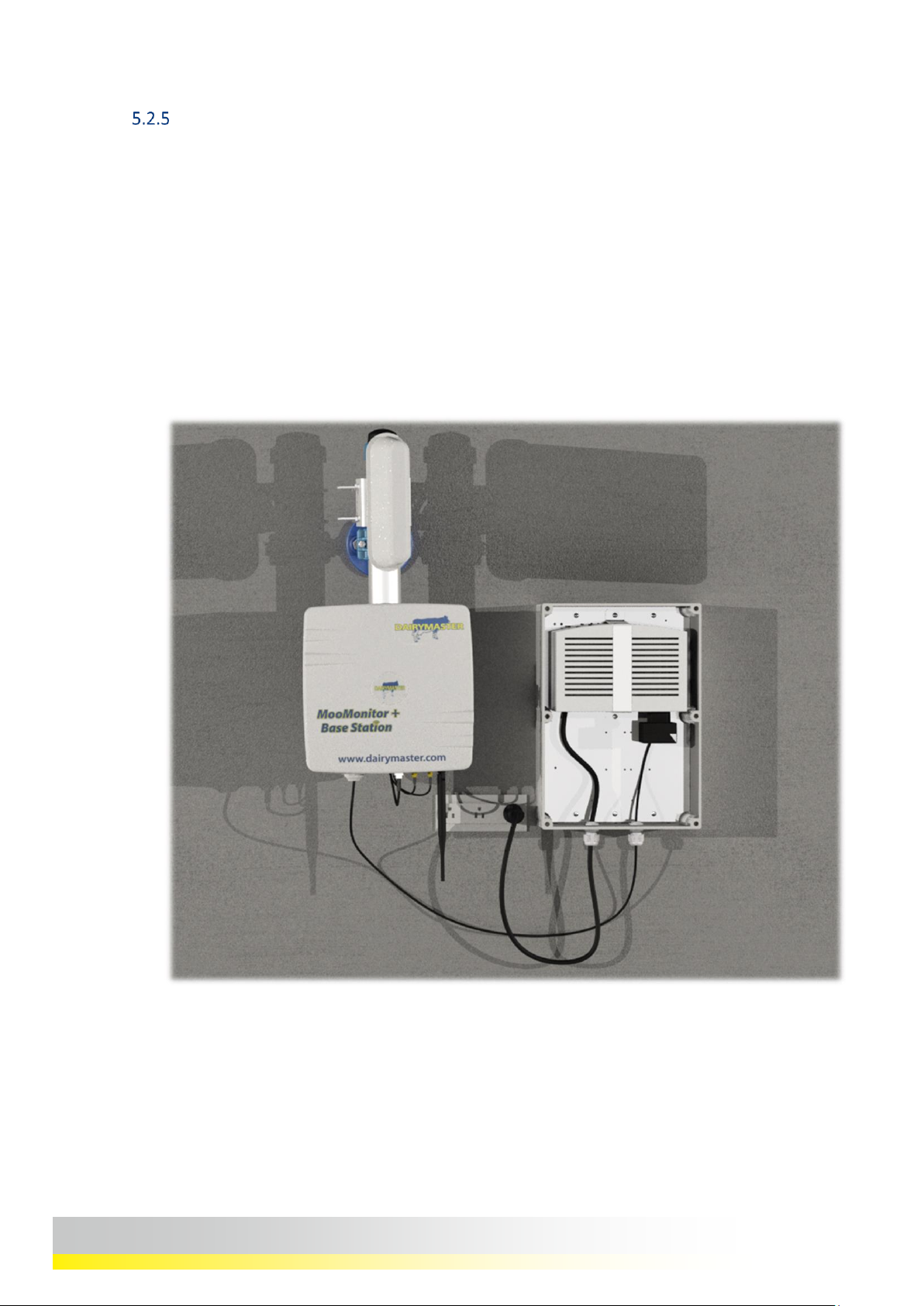
Installing a Voltage Regulator to the Base Station (USA installations only)
In situations where an unstable power supply is present to the basestation a voltage
regulator may be required.
The client’s electrical contractor must provide an electrical connection as
discussed in section 5.1
The voltage regulator is provided with a standard electrical socket and a 12V DC
adapter to connect the voltage regulator to the base station.
The installer would connect the basestation to the mains supply and plug the base
station directly into the voltage regulator. See Figure 40 &
Figure 40 – Typical view of Voltage Regulator installed with the Base Station

5-13
INM12006 – MOOMONITOR + V3.0
Copyright Dairymaster 2015
Figure 41 – Typical view of Voltage Regulator installed with the Base Station

5-14
INM12006 – MOOMONITOR + V3.0
Copyright Dairymaster 2015
Basestation LED Power up
When the base station is powered up the LED located next to the base station
connections will light up. Depending on the connection type (Wifi, GSM or
Ethernet), the LED will have a different light sequence.
Connection Type
LED Sequence
Ethernet (LAN cable)
Stays on constant
Wifi
Flashes every 1 second
GSM (Mobile)
Flashes every 5 seconds
Figure 42 - LED located next to the connections on the base station
6-15
INM12006 – MOOMONITOR + V3.0
Copyright Dairymaster 2015
6 Controls
The MooMonitor+ can be controlled and interfaced with in five ways.
1. Wi-Fi connection.
2. SMS commands
3. Dairymasters cloud based services.
4. MooMonitor+ Smartphone App
5. Through a USB to UART connection directly onto the base station PCB.
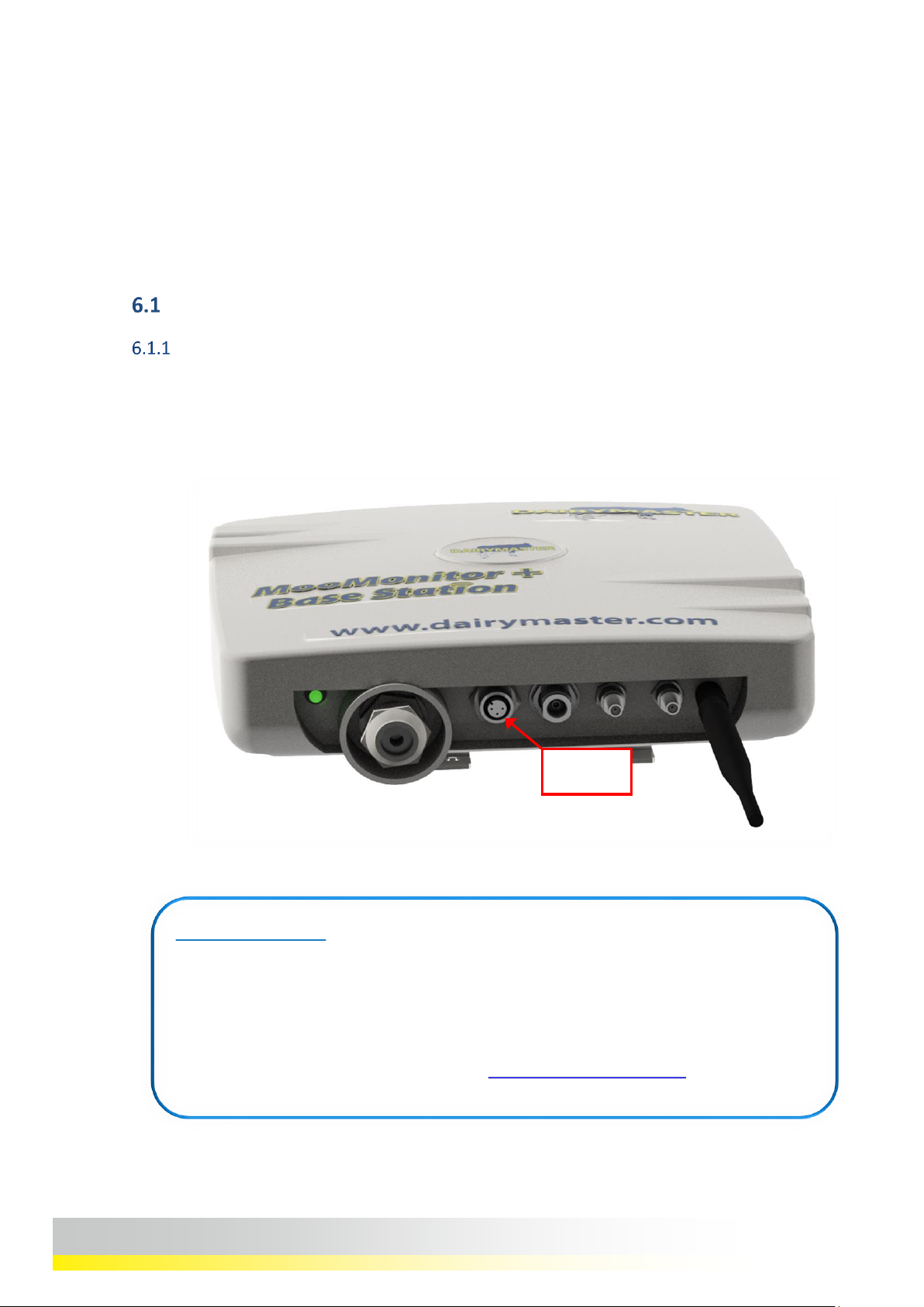
Installation Procedure
Configuring the base station using a USB to UART connection
Each base station can be configured using a physical connection onto the Base
Station PCB using the UART connection through USB. The installer will need a UART
to USB connection which will be provided by Dairymaster on request.
The UART cable is connected to the PCB as shown below.
Figure 43 – UART connection on the BaseStation
UART to
USB
Important Notes
For the moment configuration of the MooMonitor+ Basestation will be carried out
by the Dairymaster Global support team, and will be done remotely.
Installers should ensure that team viewer is installed on the local machine to
facilitate this.
Installers should contact Dairymaster at
software@dairymaster.ie
to arrange this.
6-16
INM12006 – MOOMONITOR + V3.0
Copyright Dairymaster 2015
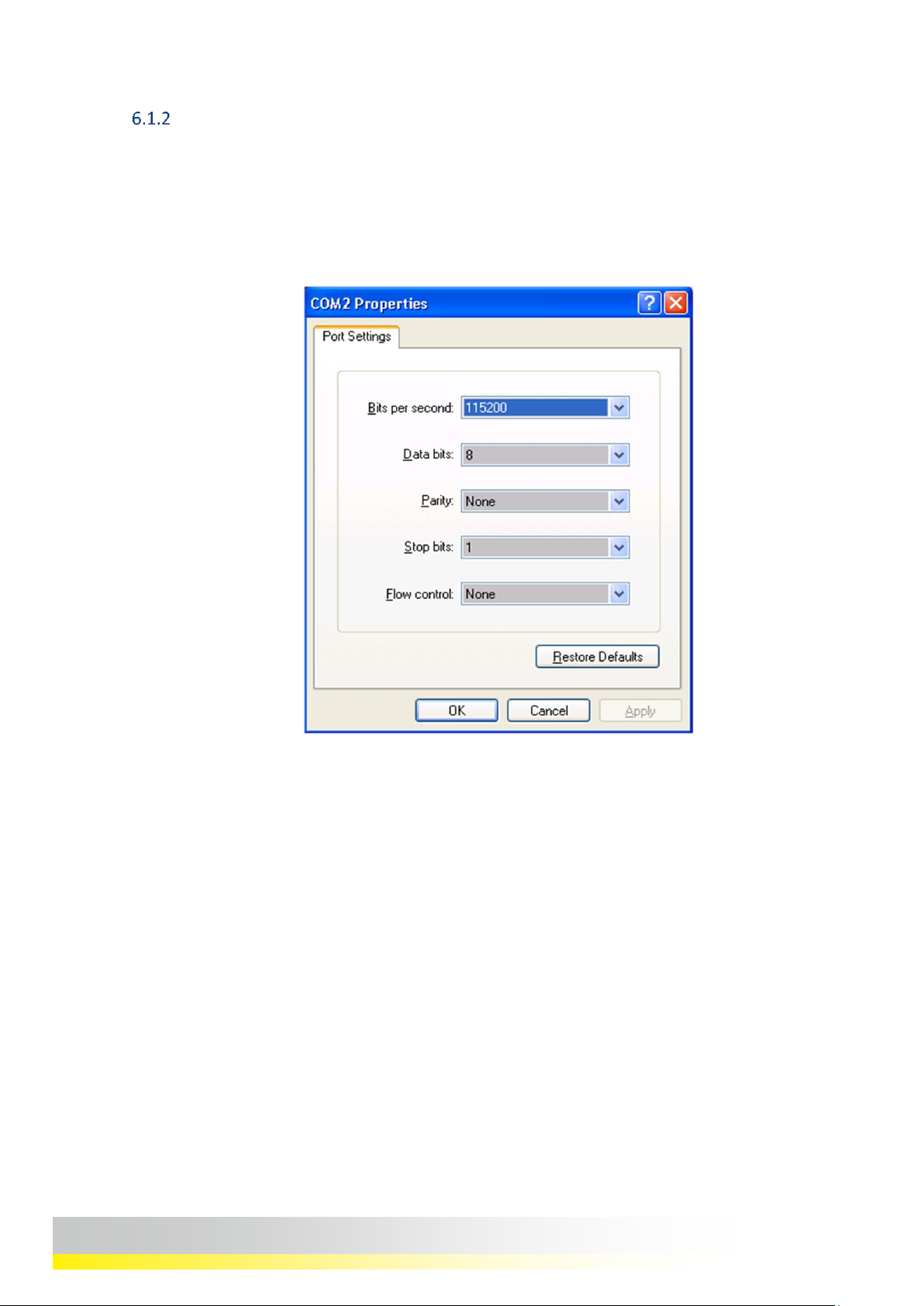
Configuring the base station using a UART connection
Once the connection to the board has been made the user will need to adjust the
com port settings on the pc to ensure that the PC and the MooMonitor base station
will communicate.
The com port settings can be accessed through My Computer\Control Panel\Device
Manager. Choose the appropriate USB comport and enter the following settings.
Once a connection has been established the user must use Hyper Terminal to
communicate with the base station. Hyper terminal is available online from a
number of sources.
Figure 44 – Com Port settings

6-17
INM12006 – MOOMONITOR + V3.0
Copyright Dairymaster 2015
6.1.2.1 Step 1: Accessing the base station using UART
When accessing the base station, it will display information about the base stations
current configuration and software version.
As per the Wi-Fi configuration options a value of 1 turns a feature on and a value of
turns a feature off.
As can be seen above the base station states the following information on boot up.
1. The Software version running on the device.
2. The device Address.
3. The Device ID
4. The Time
5. The number of records stored on the device.
6. Cloud connectivity active via mobile
7. Logging levels: The device is default is 1. The higher the level of logging
the more information that is logged.
8. Logging General: this logs general information about the device and is
used by Dairymaster for debugging or troubleshooting any issues a base
station may be having.
9. Log Wi-Fi: Device Logs are sent over the Wi-Fi
10. Log Mobile: Device Logs are sent over the GSM.
11. Radio Transmitters which are Active:
6.1.2.2 Step 2. Configuring the Farm ID and the base station ID
Once the base station has gone through its initial start-up process the device will be
ready for configuration. The installer will need to type in the installation password
into the install wizard and press enter to proceed.
Figure 45 – Step 1 UART Configuration
6-18
INM12006 – MOOMONITOR + V3.0
Copyright Dairymaster 2015
The password allows access to configure the device. The password is 1968.
To begin configuration, the installer will need to type ‘Install’ and hit Enter on the
keyboard.
For the installer to edit any given command, they will need to use the edit function.
This is done simply by pressing the numerical value on the key board as displayed
in window under the edit line.
Figure 46 – Password entry screen on using hyper terminal
The password is 1968.
Figure 47 – Configuring the base station identification using the
UART connection
Password entry
Items which can
be edited and
their numerical
values
Current values
Function

6-19
INM12006 – MOOMONITOR + V3.0
Copyright Dairymaster 2015
The installer will be prompted to enter a new value at this point. Press Enter on the
keyboard after a number is entered and check the new value has populated into the
FarmID or BasestationID value fields.
This procedure should be followed when entering any value to the system.
Notes:
1. The Farm ID is provided by Dairymaster. It is essential that the correct farm ID
is inputted.
2. Each MooMonitor is programmed to communicate with a specific farm ID only.
3. A MooMonitor with a different farm ID will not communicate with a base station
that does not have a corresponding farm ID.
4. The base station ID is used when multiple base stations exist on the one farm.
All base stations will have matching farm IDs but will need to have different Base
ID (Base station IDs)
Each MooMonitor will have a preferred base station to communicate with,
however if it cannot connect with its preferred base station, say station 1.
The monitor will connect to the next available station, say station 2 for example
if 2 stations exist on a farm or station 3, or 4 and so on.
To proceed with the next step press the greater-than (>) symbol on the keyboard
to move back a step press the less-than (<) symbol.
6-20
INM12006 – MOOMONITOR + V3.0
Copyright Dairymaster 2015
6.1.2.3 Step 3: Configuring the Wi-Fi using UART
This is the same procedure is as before: Pressing the numerical value on the key
board corresponding to the numbers displayed in window under the edit line.
Table 1 - Configurable Wi-Fi settings via UART
Edit
option
Description
Range
1
Wi-Fi enabled
0 = OFF, to 1 = ON
2
SSID
Sample SSID (Site dependant)
3
SSID password
Sample password (Site dependant)
4
Security type
0 = No Security
1 = WEP 64
2 = WEP 128
3 = WPA – PSK with TKIP encryption
4= WPA2 – PSK with TKIP or AES encryption
5= WPA - TKIP or AES encryption Enterprise with EAP – TLS
or PEAP-MSCHAPv2 (If CA parameter is empty returns
ERROR 222)
6 = WPA2 – AES Enterprise with EAP – TLS or PEAPMSCHAPv2 (If CA parameter is empty returns ERROR 222)
7 = EAP-MD5 and static WEP 64
8 = EAP-MD5 and static WEP 128
105 = WPA-TKIP Enterprise with EAP-TLS or
PEAP- MSCHAPv2. RADIUS Certification Verification will
be skipped.
106 = WPA2-AES Enterprise with EAP-TLS or PEAPMSCHAPv2. RADIUS Certification Verification will be
skipped.
5
Active FTP
0 = Active FTP Disabled
1 = Active FTP Enabled
6
Time Server Trys
Number of attempts to connect to Time server before a
reset is performed
Figure 48 - Configuring the Wi-Fi settings using UART
Items which can be
edited and their
numerical values
Items which can be
edited
6-21
INM12006 – MOOMONITOR + V3.0
Copyright Dairymaster 2015
7
Scan Access Point
This will scan and return any available Wifi Network Access
points within range
8
Test connection
(Shows the connection
status)
Not Connected, or Connected
Once a successful connection has been made the interface will display the strength
of the wireless connection and the ping test results for the connection.
It is advisable to ensure the strongest possible Wi-Fi signal and the lowest possible
ping time. A slow ping or poor signal can lead to loss of data.
To proceed with the next step, press the greater-than (>) symbol on the keyboard to
move back a step press the less-than (<) symbol.
Figure 49 – Wi-Fi connection established signal strength and ping
available for review via UART
Wi-Fi Status
Items which can be
edited and their
numerical values
Items which can be
edited

6-22
INM12006 – MOOMONITOR + V3.0
Copyright Dairymaster 2015
6.1.2.4 Step4: Configuring the GSM connection using UART
The base station can communicate to the cloud using a GSM connection.
Table 2 - Configurable GSM settings via UART
Edit
option
Description
Range
1
Mobile enabled
0 = OFF, to 1 = ON
2
APN
Sample live.vodafone.ie (provider dependant)
3
APN Username
Sample username (provider dependant)
4
APN Password
Sample password (provider dependant)
5
Service Centre
Sample +35387600000 (provider dependant)
6
Service Mobile
Dealer or Service agent number
7
Mobile 1
Customer Number 1
8
Mobile 2
Customer Number 2
To proceed with the next step press the greater-than (>) symbol on the keyboard
to move back a step press the less-than (<) symbol.
Important Note
1. The installer must ensure that an adequate 3G or 4G connection is
available on the farm and that the base station antenna is connected
with a strong mobile connection in the event that this is the base
stations only connection to the cloud based services.
2. The installer/dealer should inform the customer that data charges
may apply depending on the telecoms provider and a suitable data
plan will be required.
Figure 50 – configuration of the GSM connection
Items which can be
edited
Mobile Signal
Items which can be
edited and their
numerical values

6-23
INM12006 – MOOMONITOR + V3.0
Copyright Dairymaster 2015
6.1.2.5 Step 5: configuring the Cloud connection using UART
The cloud connection can be configured to use the mobile network or an available
Wi-Fi connection.
The base station will default to a Wi-Fi connection in the event of the mobile
connection being disabled.
Table 3 – Cloud connection setting via UART
To proceed with the next step press the greater-than (>) symbol on the keyboard
to move back a step press the less-than (<) symbol.
Edit
option
Description
Range
1
Cloud connection via
mobile
0 = OFF, to 1 = ON
2
Cloud polling interval
Interval at which the MooMonitor checks
on cloud services for updates.
Factory Default is 20 seconds.
Items which can be
edited and their
numerical values
Items which can be
edited
Figure 51 –Configuring the Cloud connections using UART

6-24
INM12006 – MOOMONITOR + V3.0
Copyright Dairymaster 2015
6.1.2.6 Step 6. Configuring the base station radio link using UART
Each base station has a 5 radios by default to allow a wider spectrum to be
accommodated on site in the event of interference from an outside radio source.
The ability to change radio channels and thereby radio frequencies will allow the
installer to ensure that any unwanted interference from signals at a similar
frequency will be avoided.
Table 4 – List of frequencies available through
Radio Transmitter
Frequency
Radio 1
868.0 MHz(EUROPE ONLY)
Radio 2
868.2772 MHz(EUROPE ONLY)
Radio 3
869.3 MHz(EUROPE ONLY)
Radio 4
914 MHz (USA ONLY)
Radio 5
915 MHz(USA ONLY)
Figure 53 – View of the PCB installed in the base station
The five radios are shown above.
Radio channels 1 to 5
going left to right
Figure 52 – Configuration of the radio channels using UART
Items which can be
edited and their
numerical values
Items which can be edited
and their numerical
values.
Note: When a radio is
active, the corresponding
IAP should also be active.

6-25
INM12006 – MOOMONITOR + V3.0
Copyright Dairymaster 2015
The same procedure can be followed when configuring the radios as in the previous
steps.
If the installer needs to activate another radio say Radio channel 1. They will need
to edit radio channel 1, by pressing 1 and following the screen prompts typing Y for
each of the prompts.
Once the new radio channel is active the installer will need to de-activate the old
radio channel. This is done by following the same procedures as outlined above.
Figure 54 – Configuring the radio station using the UART connection
Note: When a radio is
active, the corresponding
IAP should also be active.
Figure 55 - Configuring the radio station using the UART connection

6-26
INM12006 – MOOMONITOR + V3.0
Copyright Dairymaster 2015
If the installer needs to de-activate another radio say Radio channel 3, they will need
to edit radio channel 3 by pressing 3 and following the screen prompts typing N for
each of the prompts.
To proceed with the next step, press the greater-than (>) symbol on the keyboard
to move back a step press the less-than (<) symbol.
Note: When a radio is deactivated
then corresponding IAP should also
be deactivated.
Figure 56 - Configuring the radio station using the UART connection

6-27
INM12006 – MOOMONITOR + V3.0
Copyright Dairymaster 2015
6.1.2.7 Step 7: Configuring device logging using UART.
Each base station can be configured to create log files for its activity.
Logging should not be altered unless stated by a Dairymaster technical customer
support agent.
Logging level: this is defaulted to 1. The higher the level of logging the more
information that is logged.
Logging General: Logs general information about the device and is used by
Dairymaster for debugging or troubleshooting any issues a base station may be
having.
Log Wi-Fi: device logs are sent over the Wi-Fi
Log Mobile: Device logs are sent over the GSM.
Numerical
value
Logging
Range
1
Log Level
0 Logging OFF,
1 Logging ON.
2
Log General
0 Logging OFF,
1 Logging ON.
3
Log WI-FI
0 Logging OFF,
1 Logging ON.
4
Log Mobile
0 Logging OFF,
1 Logging ON.
The installer may configure device logging using the same procedures as in the
previous steps.
To proceed with the next step press the greater-than (>) symbol on the keyboard
to move back a step press the less-than (<) symbol.
Figure 57 – Configuring event logging using UART
Items which can be
edited and their
numerical values

6-28
INM12006 – MOOMONITOR + V3.0
Copyright Dairymaster 2015
Once the event logging has been configured the device should be ready for normal
operation.
The installer will see a note appear stating the device is exiting install mode.
To proceed and complete the device configuration press the greater-than (>)
symbol on the keyboard to move back a step press the less-than (<) symbol.
The device will then begin populating the screen with device information and the
configuration is complete.
Figure 58 – Final screen on the UART configuration tool

6-29
INM12006 – MOOMONITOR + V3.0
Copyright Dairymaster 2015
MooMonitor+ Android App (Version 2.0)
App Overview
The MooMonitor+ Android App allows the User to interface with the MooMonitor+
system, giving them the ability to send and receive information from the devices
and get a real time view of the data collected for their animals.
The app will allow the user to carry out a range of functions from their Smartphone
such as the following:
Receive alerts for Cows that are Active/Suspect/Health Alert
View individual Cow Data
View Individual Cow Activity/Rumination/Feeding/Resting Graphs
Add events for the Cow such as Add Heat, Add Insemination, Add Calving
Date, etc.
Set up cows for Scheduled and Permanent Drafting
The MooMonitor+ App can be downloaded from the Google Play Store.
When the App has downloaded it will appear on the Smartphone home screen
(Figure 59).
Figure 59 – MooMonitor + App Icon
and typical home screen

6-30
INM12006 – MOOMONITOR + V3.0
Copyright Dairymaster 2015
Launching the App
When launched for the first time the MooMonitor+ App will automatically redirect
you to the settings menu within the app.
Within the settings menu the app will require the user to enter the credentials
required to log into the system see Figure 60.
These credentials will be provided to the user by Dairymaster and consist of the
user name and password allocated to the specific user’s farm. Input your Username
and Password into the fields shown in Figure 60. The Username and Password will
be common amongst any device the user logs into.
Once the credentials have been entered and the Click Save to store the information.
Figure 60 - Settings Menu on the
Android App
Note
At this point you can also decide whether you wish to receive Push Notifications.
This option allows the App to send you a notification when an alert is triggered.

6-31
INM12006 – MOOMONITOR + V3.0
Copyright Dairymaster 2015
MooMonitor+ Android App User interface
Upon opening the app the Summary Screen will
appear.
This will give a summary of the 6 different alert lists
within the selected farm.
The number of cows in each group will be visible
below each alert icon.
The Basestation connectivity is also visible at the
top right of the screen
- Green: Connected
- Red: Disconnected
Heat Symbol
Displays all cows with increased activity on the farm including pregnant
Cows, Cows in Heat, Cows due to calve and cows that have had an AI or
a confirmed heat within the last 4 days.
Suspect Symbol
This is a list of the cows that are suspected to be in Heat. Their activity
levels have increased but they have not yet overcome the Activity
threshold. Farmers can identify these cows for further monitoring.
Behaviour Alert Symbol
The third symbol shows the cows that are displaying abnormal
behaviour such as a decrease in rumination, feed intake, activity,
increased resting etc.
High Activity Symbol
This Icon will show the cows that are showing high levels of activity and
therefore are identified as in heat. These cows will show factors such as
high activity levels, decreased rumination, etc.
Draft Symbol
Full list of cows in the herd. The number shown underneath signifies the
cows to be permanently drafted. Cows can be set up to draft by
choosing 0, 1 or 2 in this table.
Watch Symbol
This is the list of animals that have been marked for further monitoring
or treatment.
Figure 61 - Android App
Summary Screen

6-32
INM12006 – MOOMONITOR + V3.0
Copyright Dairymaster 2015
6.2.3.1 Animal Tables
Selecting any of the 6 alert icons will open up a tabulated list of the cows for that
alert. The table contains the information for each individual cow such as Cow ID,
Days in Milk (DIM), Last Heat, Last insemination (Last Insem), Number of
Inseminations (Num Insems) and the Group Number (Group). The drafting table
generates a different table which is outlined in section 6.2.3.2.
The colour codes at the left indicate the suitably of each cow for breeding. This is
assigned to each cow based on the information input into the system for each cow.
The colour code hint is accessed by selecting the help icon at the top right of the
screen which gives an explanation of each colour code (see below).
The information in the table can be sorted by each individual column by selecting
the column header at the top of the screen.
Summary Screen
This will show when the information was last updated or
currently being updated i.e. when the App last
downloaded information from the cloud. The current
status of the base station is also shown in this ribbon. The
user may search any known Cow ID by selecting the
search icon, entering the Cow ID and pressing on search.
Figure 62 - Tabulated list of Cows along with the Colour Code hint

6-33
INM12006 – MOOMONITOR + V3.0
Copyright Dairymaster 2015
6.2.3.2 Draft Table
The Draft table generates a list of all cows in the herd. The user can toggle between
the Permanent drafting list and the scheduled drafting list by selecting the
Scheduled or Permanent icon on the top ribbon.
The table contain information including Cow ID, Tag ID, draft pin, Group number
and if the cow is being weighed.
Figure 63 - Draft Table

6-34
INM12006 – MOOMONITOR + V3.0
Copyright Dairymaster 2015
Figure 64 - Android App Options Menu
Android App Options Menu
On the Summary screen by sliding the screen
from left to right, the Options Menu will be
displayed see Figure 64.
This menu gives a list of eight different options
see Table 5.
Table 5 – Summary Screen Options
Option
Meaning
Farm Name
Allows the user to access other
farms if applicable.
Summary
Displays the Home Screen
Heat
Displays the Cows in Heat
Suspect
Displays the Suspect Cow List
Behaviour
Alert
Displays the Behaviour Alert List
High Activity
Displays the High Activity List
Draft
Displays all cows in the herd
Watch
Displays the cows on the Watch list
All
Shows a list of all cows on the farm
Assign MM+
Allows the user to assign a
MooMonitor+ to a cow.
Extras
Option
Meaning
Settings
Opens the Settings Menu
Scheduled
Draft
Displays cows on the Scheduled
Draft list
Batch
Selection
Allows the user to select any batch
of animals and add an event for
them animals
Herd Data
Display scatter graphs of individual
cows and performance against the
herd average.
Test Farm 1
Figure 65 – Android App Options
Menu (scrolled)

6-35
INM12006 – MOOMONITOR + V3.0
Copyright Dairymaster 2015
Working with Multiple Farms
If the user has access to multiple farms, then they can switch farms by clicking on
the Farm Name in the options menu.
This will present them with a list of farms which they have access to see Figure 66.
Important Note
An important note for multi farm use is that each user should have a separate
login or each device should have a separate login.
Otherwise if two people are using the same login simultaneously on different
devices and one user switched farms then this could lead to undefined behaviour
for the second user.
Figure 66 - Android App Options Menu Farm Selection choosing Farm Menu
Test Farm 1
Test Farm 2
Test Farm 3
Test Farm 4
Test Farm 5
Test Farm 6
Test Farm 1

6-36
INM12006 – MOOMONITOR + V3.0
Copyright Dairymaster 2015
Assigning a MooMonitor+
The user can assign a MooMonitor+ to a cow by selecting the Assign MM option in
the options menu.
Enter the Cow ID and the MooMonitor+ ID.
The Cow Id will be the number either
freeze branded onto the animal or the
number of the RF ID on the animal’s ear
tag (this is farm dependant).
The MooMonitor+ ID is the number
located on the rear of MooMonitor+
unit.
Figure 68 - Assign MooMonitor
Figure 67 – Location of the
MooMonitor + ID on the rear of tag

6-37
INM12006 – MOOMONITOR + V3.0
Copyright Dairymaster 2015
Viewing Cow data
A cow’s individual data can be viewed by searching for the cow ID in the search bar,
by clicking into any of the six groups on the home screen and selecting any individual
cow or by selecting the All Cows list in the Options menu.
When the user clicks into an Individual Cow the screen will display the animal’s
information i.e. Cow ID, Last Heat, MooMonitor ID, Max. Activity, No of Heats, No.
of Inseminations, Lactation no. (see below).
By tapping on the cow summary at the top of the screen, the list of previous events
for that cow will appear instead. The user can toggle between both these
information screens.
By scrolling down it will also display the graphs associated with that cow (see
below).
The Daily & hourly Activity and Rumination Graph, the Rumination graph, resting
graph, feeding graph and Daily Activity Intensity graph will all be displayed.
To view another animal in the table simply swipe the screen left or right to show
the information for the next or previous cow on the list.
Figure 69 - Individual Cow
Summary
Figure 70 - Individual Cow
Summary Graphs
Figure 71 – Daily Activity
graph

6-38
INM12006 – MOOMONITOR + V3.0
Copyright Dairymaster 2015
The Activity and Runination Graphs display the Heat Alerts and Behaviour Alerts for that
specific animal.
The Red Bullseye denotes a heat
The Blue Bullseye denotes a Behaviour Alert.
The user can select any of these bullseye’s to view a summery of the information fo rthat
event.
Figure 72 - Daily Activity & Rumination Graph

6-39
INM12006 – MOOMONITOR + V3.0
Copyright Dairymaster 2015
Adding Events
Users may add a number of events within the app which will assist the farmer to
organise the data generated by the MooMonitor+ system.
An event can be added by selecting the type of event at the bottom of the screen.
There are also other options such as Remove Collar from the cow, add the cow to
the Watch list, remove the cow from the watch list and remove that cow from the
system. By scrolling left to right more event options can be chosen.
There are a total of 12 different events that can be undertaken using the Android
App:
Remove Collar
Add Calved
Add DNB
Add Watch
Add Draft
Preg Check
Add Heat
Add BCS
Behaviour Alert
Add Insemination
Dry Off
Remove Animal
Figure 73 – Add Event Options
Figure 74 - Scroll left and right to view the full list of the options for each cow.

6-40
INM12006 – MOOMONITOR + V3.0
Copyright Dairymaster 2015
6.2.8.1 Add Heat Event
The user may at any time add an animal heat by pressing the Add Heat icon at the
bottom of the screen.
When an animal has a heat added they will be automatically added to the heats list.
1. The user will be prompted to Ignore or Confirm the heat alert.
2. The cow ID and the date of the heat event along with the time will
automatically be entered.
3. The time and date may be manually changed by the user if required.
4. Any comments the farmer may have can also be added.
5. Once the details have been entered the user will need to click the save icon
to store the information.
Figure 75 – Adding a Heat Event

6-41
INM12006 – MOOMONITOR + V3.0
Copyright Dairymaster 2015
6.2.8.2 Add Insemination event
The user may at any time add an animal insemination event by selecting the Add
Insem icon at the bottom of the screen.
1. The cow ID and the date of the insemination event along with the time will
automatically be entered.
2. The time and date maybe manually altered by the user if required.
3. The user will need to add in the siring animal ID to the app in the sire
dropdown menu. This list is generated by pressing the menu button on the
top right of the screen, entering the Sire ID, adding it to the list and pressing
save at the bottom of the screen. These sire ID’s will then appear on the
drop down menu in the Add Insemination screen.
4. Any comments the farmer may have can also be added.
5. Once the details have been entered the user will need to click the save icon
to store the information.
Figure 76 - Add insemination event

6-42
INM12006 – MOOMONITOR + V3.0
Copyright Dairymaster 2015
6.2.8.3 Adding a calving event
When a cow has calved the information of the event can be entered by selecting
the Calved icon at the bottom of the screen.
Information such as the CowID, the Date of the calving event, the difficulty of the
calving and no of calves, along with any comments the farmer may wish to add.
1. The cow ID and the date of the calving event along with the time will
automatically be entered.
2. The time and date maybe manually altered by the user if required.
3. The difficulty of the calving and number of calves may also be entered.
4. Any comments the farmer may have can also be added.
5. Once the details have been entered the user will need to click the save icon
to store the information.
Figure 77 – Add Calving Event

6-43
INM12006 – MOOMONITOR + V3.0
Copyright Dairymaster 2015
6.2.8.4 Add Drafting Event
It is now possible to add a drafting event for each animal. There is a range of drafting
options available to the user when drafting a cow.
Select the Add Draft symbol at the bottom of the cow summary screen. A list of
drafting options will appear on the screen. The cow can be set up for a Scheduled
Draft or Permanent Draft from this menu.
There also options to add that cow to the Watch list, draft the cow to Pin 1
permanently, Draft the cow to Pin 2 permanently and setting the draft to 0.
Figure 78 - Add Drafting Event
Figure 80 - Add Permanent Draft
Figure 79 - Add Scheduled Draft

6-44
INM12006 – MOOMONITOR + V3.0
Copyright Dairymaster 2015
6.2.8.5 Add Body Condition Score
The Body Condition Score of the animal can be added by selecting Add BCS at the
bottom of the cow information screen.
The Cow ID, Date & time will be populated automatically. The date and time can be
changed manually if required. The BCS for the cow is selected from the dropdown
menu. Any comments the user may have can be entered also.
Figure 81 - Add Body Condition Score

6-45
INM12006 – MOOMONITOR + V3.0
Copyright Dairymaster 2015
6.2.8.6 Add Dry Off Event
The user may add a Dry Off event by selecting the Dry Off icon at the bottom of the
screen.
1. The cow ID and the date of the dry off event will be automatically entered.
The user may enter a different date if they require.
2. Any comments the farmer may have can also be added.
Once the details have been entered the user will need to click the save icon to store
the information
Figure 82 - Add a Dry Off Event.

6-46
INM12006 – MOOMONITOR + V3.0
Copyright Dairymaster 2015
6.2.8.7 Add Do Not Breed (DNB) Event
In the event that an animal has genetic issues or is of poor health, the user may
select the animal for do not breed. At the bottom of the cow overview screen select
the DNB icon.
This means the animal can be excluded automatically from inseminations.
1. Enter the Start and Finish dates and times.
2. Any comments the farmer may have can be entered here.
3. Once the details have been entered the user will need to click the save icon
to store the information.
Figure 83 - Add Do Not Breed Event

6-47
INM12006 – MOOMONITOR + V3.0
Copyright Dairymaster 2015
6.2.8.8 Log a Pregnancy Check
The farmer can keep records of animal pregnancy checks and veterinary scans,
which will assist the farmer in building a profile of which animals struggle to get
pregnant.
1. The cow ID and the date of the event along with the time will automatically
be entered.
2. The result of the pregnancy check (Positive or Negative) will need to be
entered.
3. Any comments the farmer may have.
Figure 84 - Add Pregnancy Check Event

6-48
INM12006 – MOOMONITOR + V3.0
Copyright Dairymaster 2015
6.2.8.9 Adding a Behaviour Alert
A health event may be added for any animal by selecting the Behaviour Alert icon
at the bottom of the cow overview screen.
This will open up the Add Behaviour Event window on the Screen.
1. The cow ID and the start and end date and time of the behaviour event will
automatically be entered.
2. The start and end time and date maybe manually altered by the user if
requires.
3. The type of behaviour event must be selected from the illness dropdown list.
4. Any comments the farmer may have can also be added.
5. Once the details have been entered the user will need to click the save icon
to store the information.
Figure 85 – Adding a health event

6-49
INM12006 – MOOMONITOR + V3.0
Copyright Dairymaster 2015
Batch Selection
The user may add an event to groups of animals at once by using the Batch Selection
feature on the Android App. The Batch Selection feature is accessed by selecting
the options menu at the top left of the home screen. Select Batch Selection at the
bottom of the settings list.
The Batch Selection screen will display a list of the various groups of animals in the
herd such as the Heat, Suspect, High Activity, Behaviour, Drafts & All Cow lists etc.
By selecting into any of these lists, the user can then select a number of cows from
the list by ticking the box next to each cow (Figure 86).
After selecting the cow ID’s, the user can add an event to the selected group of cows
by selecting one of the events on the scroll bar at the bottom of the screen
Figure 86 - Entering Batch Selection on the Android App

6-50
INM12006 – MOOMONITOR + V3.0
Copyright Dairymaster 2015
Viewing Herd Data
The user can view individual herd scatter graphs to determine how each cow is
performing against the herd average. The graph compares Resting (y-axis) with
Rumination + Feeding (x-axis). Different groups can be selected from the dropdown
at the top right of the screen.
Select Herd Data from the settings menu. This will proceed to the Herd Analysis
screen. The herd graph will be displayed at the bottom of the screen.
By selecting any of the coloured dots on the
graph, the information for that animal will be
displayed at the top of the screen.
A chart of the cow’s Activity, Resting, Feeding
and Rumination performance against the
average performance of the herd will also be
shown.
Each cow is colour coded according to the colour
symbol assigned to them from the data which
has been inputted into the system (See section
6.2.3.1).
Figure 87 - Herd Analysis option on the Android App
Figure 88 - Chart Data displayed
for the individual Animal.

6-51
INM12006 – MOOMONITOR + V3.0
Copyright Dairymaster 2015
Individual Groups and specific dates can be selected by entering the dropdown
menu at the top right of the screen.
Figure 89 - - Choose from the list of groups for specific graphs to be displayed

6-52
INM12006 – MOOMONITOR + V3.0
Copyright Dairymaster 2015
View Basestation Status
The User may view the Basestation Status and information about the tags
communicating with the system.
To view the Basestation information, select the Basestation icon at the top right of
the home screen.
The system will show the number of collars which have communicated with the
Basestation in the last 24hrs and the collars which have been out of range for longer
than that period.
Figure 90 – View Basestation Status
 Loading...