

TPM-RKE Analyzer
9936
Version 06.03 Daimler Chrysler
User’s manual
Reference: QS-258DCA-U

User guide
REGULATORY STATEMENTS
This device complies with Part 15 of the FCC Rules. Operation is subject to the following
two conditions;
(1) this device may not cause harmful interference, and
(2) this device must accept any interference received, including interference that may
cause undesired operation.
“Changes or modifications not expressly approved by the manufacture could void the
user's authority to operate the equipment.”
“NOTE: This equipment has been tested and found to comply with the limits for a Class B
digital device, pursuant to Part 15 of the FCC Rules. These limits are designed to provide
reasonable protection against harmful interference in a residential installation. This
equipment generates, uses and can radiate radio frequency energy and, if not installed and
used in accordance with the instructions, may cause harmful interference to radio
communications. However, there is no guarantee that interference will not occur in a
particular installation. If this equipment does cause harmful interference to radio or
television reception, which can be determined by turning the equipment off and on, the
user is encouraged to try to correct the interference by one or more of the following
measures:
-- Reorient or relocate the receiving antenna.
-- Increase the separation between the equipment and receiver.
-- Connect the equipment into an outlet on a circuit different from that to which the receiver
is connected.
-- Consult the dealer or an experienced radio/TV technician for help.
WARNING: Changes or modifications not expressly approved by the manufacturer may
violate the user's authority to operate the equipment.
Industries Canada:
The installer of this radio equipment must ensure that the antenna is located or pointed
such that it does not emit RF field in excess of Health Canada limits for the general
population; consult Safety Code 6, obtainable from Health Canada’s website
www.hc-sc.gc.ca/rpb
"

User’s Manual
TABLE OF CONTENTS
User guide 2
TPM-RKE ANALYZER 9936 ............................................................................................. 2
.1 DESCRIPTION OF THE TPM-RKE ANALYZER 9936 ........................................................................ 2
.2 FEATURES .......................................................................................................................................... 3
..1 Radio frequencies ........................................................................................................................... 3
..2 Type of valve .................................................................................................................................. 3
.3 CONNECTORS .................................................................................................................................... 4
..1 Supply connector ............................................................................................................................ 4
..2 USB connector ............................................................................................................................... 4
..3 RS232 connector ............................................................................................................................ 4
.4 DESCRIPTION OF THE INSTRUMENT ............................................................................................... 5
..1 Power on/off key ............................................................................................................................. 5
.5 FRONT PANEL DESCRIPTION ........................................................................................................... 6
..1 Display ............................................................................................................................................ 6
..2 Lights .............................................................................................................................................. 6
..3 Keys ................................................................................................................................................ 6
.6 BATTERY SUPPLY ............................................................................................................................. 7
..1 Battery status .................................................................................................................................. 7
.7 MEASUREMENT .................................................................................................................................. 8
..1 Key measurement (RKE test) ......................................................................................................... 8
..2 Valve measurement (TPM functions) .............................................................................................. 9
.8 SETTINGS ............................................................................................................................................ 12
..1 Parameters menu ........................................................................................................................... 12
.9 STARSCAN .......................................................................................................................................... 16
..1 Data transfer ................................................................................................................................... 16
..2 TPM/RKE Analyzer program up-dating ........................................................................................... 16
.10 MENU STRUCTURE .......................................................................................................................... 17
..1 Main menu ...................................................................................................................................... 17
.11 CORRESPONDANCES TABLES ...................................................................................................... 19
..1 Vehicle / Body / valve ..................................................................................................................... 19
..2 Countries / frequencies ................................................................................................................... 19
................................................................................................................................................................ 19
Index 20
User guide TPM-RKE Analyzer Page 1/20
User guide
TPM-RKE ANALYZER 9936
.1 DESCRIPTION OF THE TPM-RKE ANALYZER 9936
The principal of this instrument is to awaken and then retrieve data from smart
valves mounted on vehicle wheels in order to verify their identifiers.
The instrument interacts with the smart valves without contact through wireless
communication.
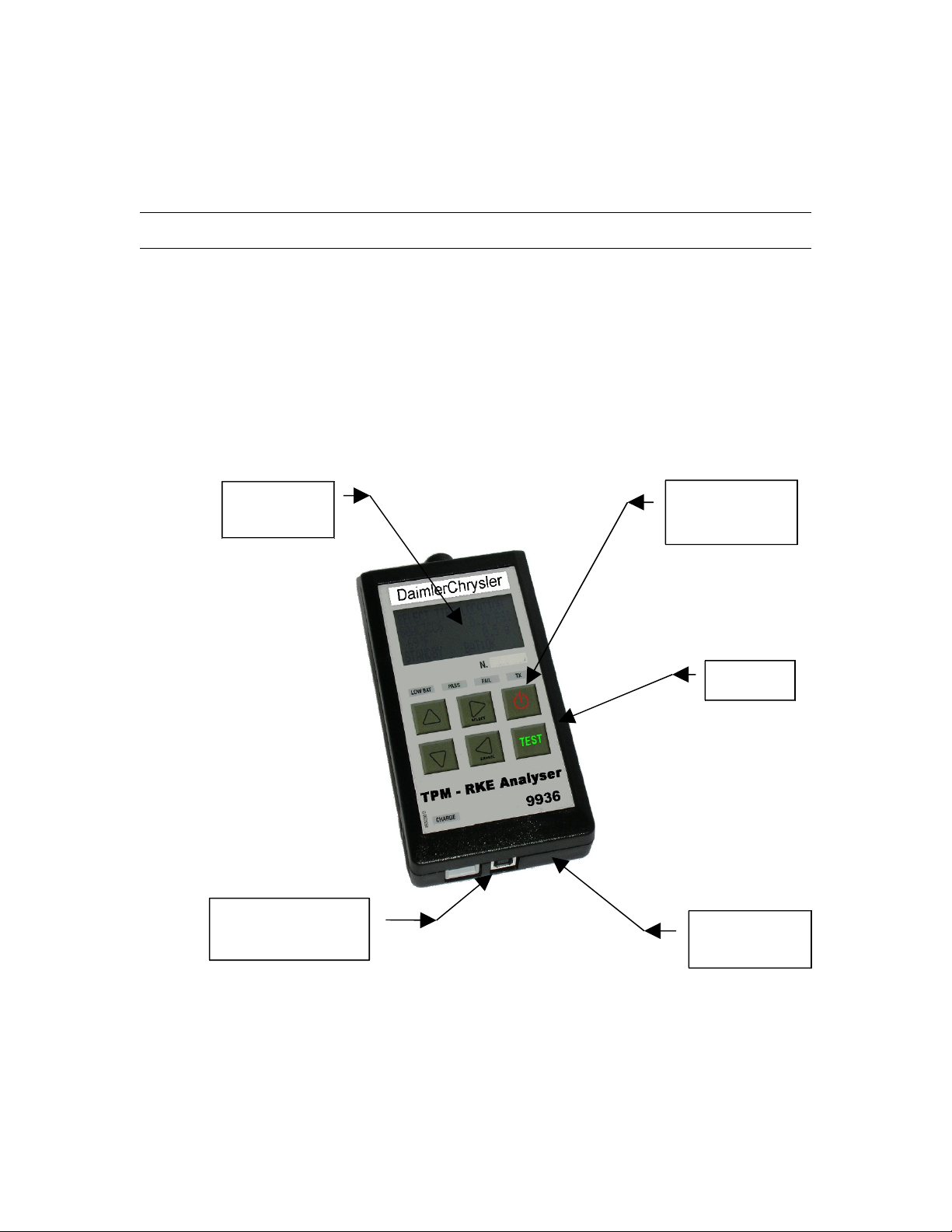
LCD
Display
RS232 (RJ45)
Connecter
Light
Indicators
Keypad
USB
Connecter
User guide TPM-RKE Analyzer Page 2/20
.2 FEATURES
..1 RADIO FREQUENCIES
Awakening transmission frequency: 125 kHz (LF).
Reception frequencies: 433 MHz or 315 MHz (RF).
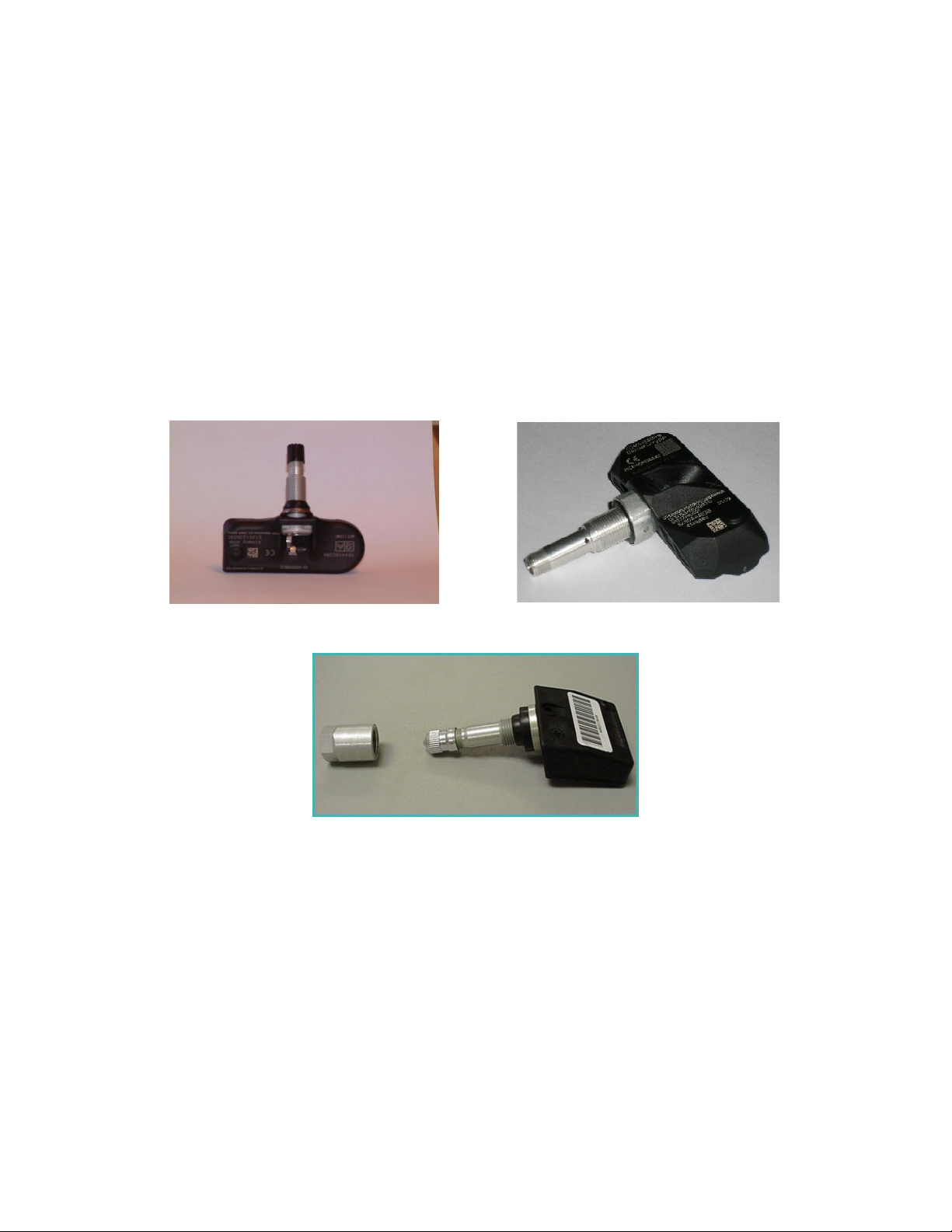
..2 TYPE OF VALVE
This instrument is especially designed for the measurement of the Siemens and
Schrader valves installed into Daimler-Chrysler vehicles.
Siemens
Siemens
Schrader
User guide TPM-RKE Analyzer Page 3/20
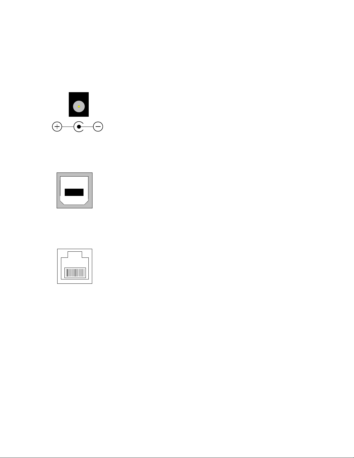
.3 CONNECTORS
..1 SUPPLY CONNECTOR
To supply the instrument and recharging the internal battery.
The voltage of the charger is a 24 V DC.
..2 USB CONNECTOR
The USB connector allows the instrument software programs to
be updated.
StarScan tool can retrieve information through the USB
connector.
..3 RS232 CONNECTOR
Not used.
User guide TPM-RKE Analyzer Page 4/20
.4 DESCRIPTION OF THE INSTRUMENT
ATEQ VT 60
Version 06.03
MAIN MENU
> RKE TEST
TPM FUNCTIONS
SETTINGS
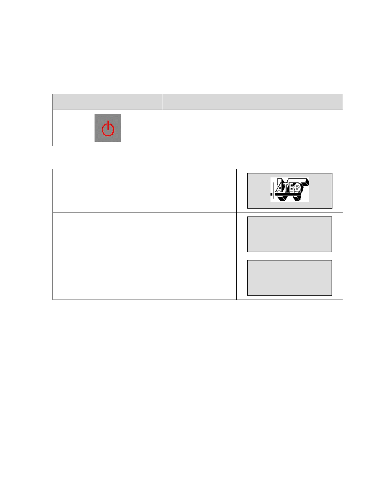
..1 POWER ON/OFF KEY
KEY FUNCTION
Power on: Press this key to power on the instrument.
Power off: Press and hold the key (more than 3
seconds) to power off the instrument.
..1. Power on
At power on, it displays the logo.
Then it displays the software revision number.
Then the tool displays the main menu and the operator
can select desired function.
User guide TPM-RKE Analyzer Page 5/20

.5 FRONT PANEL DESCRIPTION
MAIN MENU
> RKE TEST
TPM FUNCTIONS
SETTINGS
LOW BAT
PASS
FAIL
TX
CHARGE
..1 DISPLAY
The LCD screen displays the parameters menus and
the measurements results.
..2 LIGHTS
Battery level light: When this light is on, the battery level is too low, charge it.
Pass test light: When this light is on, the instrument has correctly
received the frame from the valve (or the RKE).
Fail test light: When this light is on, the instrument has not received the
frame from the valve (or the RKE).
Transmission light: When this light is flashing, the instrument is
currently transmitting a 125 KHz frequency to activate a valve.
charged.
..3 KEYS
Power on and off the instrument.
Navigation menu, "up".
Navigation menu, "down".
Select Key, press to enter in the chosen function or validate a parameter.
Cancel key, return to the previous menu or function without parameter validation.
Test Key, to initiate a test cycle.
Battery charging light: This light turns on when the instrument is being
User guide TPM-RKE Analyzer Page 6/20

.6 BATTERY SUPPLY
LOW BATT
PASS
FAIL
TX
MAIN MENU
RKE TEST
TPM FUNCTIONS
> SETTINGS
PARAMETERS MENU
UNIT : METRIC
AUTO OFF: DISABLE
> BATTERY LEVEL
RECEIVER BATTERY
1: READY
2: READY
MAIN MENU
> RKE TEST
TPM FUNCTIONS
SETTINGS
The instrument uses a Li-ion battery, the autonomy depends of the number of
cycles carried out. It battery must be recharged with a 24 V DC external power
supply (Included).
..1 BATTERY STATUS
When the battery is too low, the "LOW BATT" light is
flashing for 2 seconds and the instrument will
powered off.
To see the battery status, select the "SETTINGS"
menu using the
Validate your entry with the
By using the
and
and
keys, select the
keys.
key.
"BATTERY LEVEL" menu and validate with the
key.
The instrument displays the receivers and the battery
status.
Press the
button to return to the main menu.
User guide TPM-RKE Analyzer Page 7/20

.7 MEASUREMENT
MAIN MENU
> RKE TEST
TPM FUNCTIONS
SETTINGS
EUROPE
RKE TEST
< TEST > TO START
EUROPE
1997/E
RF LEVEL
PLEASE WAIT...
EUROPE
RKE TEST
PRESS KEY FOB BUTTON
EUROPE
RKE TEST
PRESS KEY FOB BUTTON
MAIN MENU
> RKE TEST
TPM FUNCTIONS
SETTINGS
..1 KEY MEASUREMENT (RKE TEST)
This menu allows putting the instrument in key test
mode (RKE).
Select this mode with the
key,
the instrument invites you to launch the test by
pressing the
key.
Wait a second for the initialization if the instrument.
The instrument displays a horizontal bar and invites
you to test the key fob. Hold the key fob near the
antenna of the instrument (between 7 and 15
centimetres) and press any button of the key fob.
The intensity of the RF signal force is indicated on the
scale of the horizontal bar. The greater the key fob RF
signal power, the greater the horizontal bar is filled.
Press the
button to return to the main menu.
User guide TPM-RKE Analyzer Page 8/20

..2 VALVE MEASUREMENT (TPM FUNCTIONS)
MAIN MENU
RKE TEST
> TPM FUNCTIONS
SETTINGS
MODEL YEAR SELECTION
> 1997
1998
1999
MODEL YEAR SELECTION
2004
2005
> 2006 ...
BODY STYLE SELECTION
> CS
HB
KJ
BODY STYLE SELECTION
LX
RS
> WK
TRIGGER SELECTION
> READ SENSOR
PARK SENSOR
DEACTIVATE SENSOR
EUROPE
2006 .../WK
PARK SENSOR
< TEST > TO START
Use the following directions to test the functionality of a TPM sensor:
Select "TPM FUNCTION" by using the
keys and validate using the
By using the
and
keys, select the model
and
key.
year of the valve to be tested and validate using the
key (existing years from 1997 to 2006).
Next, by using the
and
keys, select the
body code of the valve to be tested and validate with
the
key (this code is in correspondence with a
vehicle).
Next, by using the
trigger selection and validate using the
and
keys, select the
key (you
may select the mode you want to trigger on the valve,
read, park, deactivation and sniffing).
Then the instrument is displaying the valve
characteristics chosen and waiting for a start cycle. To
start cycle, press the
key.
User guide TPM-RKE Analyzer Page 9/20

When the "TX" light is flashing, it indicates that the
LOW BATT
PASS
FAIL
TX
EUROPE
2006 .../WK
PARK SENSOR
TRIGGER PROCESSING
LOW BATT
PASS
FAIL
TX
SENSOR DATAS
80AA323B 240 KPa
SLEEP MODE
<SELECT>TIRE LOCATION
SENSOR DATAS
80AA323B 240 KPa
SLEEP MODE
<SELECT>TIRE LOCATION
TIRE LOCATION
> LEFT FRONT : EMPTY
LEFT REAR1 : EMPTY
LEFT REAR2 : EMPTY
LEFT FRONT : STORED
TIRE LOCATION
> LEFT FRONT : OK
LEFT REAR1 : EMPTY
LEFT REAR2 : EMPTY
LOW BATT
PASS
FAIL
TX
instrument is emitting a frame wirelessly to make the
valve respond.
First case: a valve is detected:
When the instrument has detected a frame from the
valve, the "PASS" light is on and it displays the valve
characteristics.
NB: the identifier displayed on the screen must be the
same as the one written on the valve.
To locate the valve on the car, press the
key.
Then select the valve wheel location and press the
key.
The instrument confirms the location of the valve.
And indicates the location valve on the car.
Second case: no valve is detected:
After a few moments, if no valve frame is detected, the
"FAIL" light is on, so start a new test.
User guide TPM-RKE Analyzer Page 10/20

Press the
MAIN MENU
> RKE TEST
TPM FUNCTIONS
SETTINGS
SENSOR DATAS
80AA323B 240 KPa
SLEEP MODE
<SELECT>TIRE LOCATION
Valve
identifier
Tire internal
pressure at
sea level
Valve
mode
To locate the
valve on the car
LOW BATT
PASS
FAIL
TX
button to return to the main menu.
..1. Results explanation
The picture below is an example of a valve data communication result:
..2. No valve response
If the instrument doesn't receive any information from the valve or if the valve is
not compatible with the parameters, after 36 seconds a time out on the
instrument stops its cycle and the "FAIL" light is switched on.
User guide TPM-RKE Analyzer Page 11/20

.8 SETTINGS
MAIN MENU
RKE TEST
TPM FUNCTIONS
> SETTINGS
PARAMETERS MENU
> COUNTRY : EUROPE
UNIT : METRIC
AUTO OFF: DISABLE
REGION SELECTION
> US/CAN/MEX
JAPAN
MIDDLE EAST
MAIN MENU
> RKE TEST
TPM FUNCTIONS
SETTINGS
..1 PARAMETERS MENU
This menu will allow the instrument to be configured according to the operator
preferences.
..1. Country
The parameter "COUNTRY" allows the user to select the geographic valves
region.
Select "SETTINGS" by using the
keys and validate with the
and
key.
Select the "COUNTRY" parameter and validate with
the
key.
Then select the valve region between US/CAN/MEX,
JAPAN, MIDDLE EAST, EUROPE and OTHER.
NB: the TPM function is not available for the Japan
country.
Press the
button to return to the main menu.
User guide TPM-RKE Analyzer Page 12/20

..2. Unit
MAIN MENU
RKE TEST
TPM FUNCTIONS
> SETTINGS
PARAMETERS MENU
COUNTRY : EUROPE
> UNIT : METRIC
AUTO OFF: DISABLE
UNIT SELECTION
US
> METRIC
MAIN MENU
> RKE TEST
TPM FUNCTIONS
SETTINGS
The parameter "UNIT" allows the user to choose between the "METRIC" unit and
the "US" unit.
Select "SETTINGS" by using the
keys and validate with the
and
key.
Select the "UNIT" parameter and validate with the
key.
Then select the unit between "US" and "METRIC" and
Press the
validate with the
button to return to the main menu.
key.
User guide TPM-RKE Analyzer Page 13/20

..3. Auto off
MAIN MENU
RKE TEST
TPM FUNCTIONS
> SETTINGS
PARAMETERS MENU
COUNTRY : EUROPE
UNIT : METRIC
> AUTO OFF: DISABLE
PARAMETERS MENU
COUNTRY : EUROPE
UNIT : METRIC
AUTO OFF: 5 mn <
MAIN MENU
> RKE TEST
TPM FUNCTIONS
SETTINGS
The "AUTO OFF" setting allows the user to turn off the instrument automatically
after a certain time without use. This is to save the battery before a recharge is
required.
Select "SETTINGS" by using the
keys and validate with the
and
key.
Select the "AUTO OFF" parameter and validate with
the
key.
The cursor position moves to the right of the screen
and by using the
and
keys, choose the
auto off time between "DISABLE" and 1 to 60 minutes,
key.
Press the
then validate with the
button to return to the main menu.
In the above example, after 5 minutes with no use, the instrument will switch off
automatically.
User guide TPM-RKE Analyzer Page 14/20

..4. Back light
MAIN MENU
RKE TEST
TPM FUNCTIONS
> SETTINGS
PARAMETERS MENU
AUTO OFF: DISABLE
BATTERY LEVEL
> BACK LIGHT: 0 %
PARAMETERS MENU
COUNTRY : EUROPE
UNIT : METRIC
AUTO OFF: 5 mn <
MAIN MENU
> RKE TEST
TPM FUNCTIONS
SETTINGS
The "BACK LIGHT" menu allows the user to adjust the light intensity of the
display. The back light increases the battery consumption.
Select "SETTINGS" by using the
keys and validate with the
and
key.
Select the "BACK LIGHT" parameter and validate with
the
key.
The cursor position moves to the right of the screen
and by using the
and
keys, adjust the
back light intensity, choose between 1 to 100 percent
by 1 percent increments, then validate with the
key.
Press the
button to return to the main menu.
User guide TPM-RKE Analyzer Page 15/20

.9 STARSCAN
BOOTSTRAP VT60 4.11
USB.2.00
BOOTSTRAP VT60 4.11
USB.2.00 CONFIGURED
MAIN MENU
> RKE TEST
TPM FUNCTIONS
SETTINGS
..1 DATA TRANSFER
Data transfer from the TPM/RKE Analyzer 9936 instrument to the StarScan tool.
Connect the USB cable from the TPM/RKE Analyzer 9936 instrument to the
StarScan tool, then the StarScan tool recognizes the information to download
automatically.
..2 TPM/RKE ANALYZER PROGRAM UP-DATING
Connect the USB cable between the computer and the instrument, the USB
drivers must be installed first.
Press and hold the
and the
at the same
time.
NB: in case of error of manipulation, to exit from this
menu, press the
key.
When the USB cable is connected, "CONFIGURED"
appears on the screen.
On the computer open the attached file and a browser
will appear. Click on "LOAD".
The loading progress is displayed and when
completed, the instrument will boot to the main menu.
Now it's possible to disconnect the USB cable from the
PC and the instrument.
User guide TPM-RKE Analyzer Page 16/20

.10 MENU STRUCTURE
..1 MAIN MENU
.
MAIN MENU Sub menu 1 Sub menu 2 Sub menu 3 Sub menu 4
RKE TEST
RKE TEST
V
TPM FUNCTIONS
V V V
V V
V V
V V
V
V V
V V
V V
V V
V
V V
V V
V V
V V
V
V V
V V
V V
V V
V
V V V
>
Press <TEST> to
start
1997 > 1998 >
>
1999 > 2000
2001
2002
2003
2004
>
>
>
>
>
PR READ SENSOR
SNIFFING MODE
LH > PR > WJ READ SENSOR
SNIFFING MODE
LH > PR > RS >
WJ
CS > LH > RS >
W J > ZB
CS > KJ > LH >
RS > WJ > ZB
READ SENSOR
SNIFFING MODE
READ SENSOR
SNIFFING MODE
READ SENSOR
DEACTIVATE
SENSOR
V
DEACTIVATE
SENSOR
V
DEACTIVATE
SENSOR
V
DEACTIVATE
SENSOR
TIRE LOCATION:
Left / right /
>
front / rear…
TIRE LOCATION:
Left / right /
>
front / rear…
TIRE LOCATION:
Left / right /
>
front / rear…
TIRE LOCATION:
Left / right /
>
front / rear…
TIRE LOCATION:
Left / right /
>
front / rear…
TIRE LOCATION:
Left / right /
>
front / rear…
TIRE LOCATION:
Left / right /
>
front / rear…
TIRE LOCATION:
Left / right /
>
front / rear…
TIRE LOCATION:
Left / right /
>
front / rear…
User guide TPM-RKE Analyzer Page 17/20

V V
V V
V V
V
V V V
V V
V V
V V
V V
V
V V
V
V
V
V
SETTINGS
>
2005
2006
COUNTRY
V
V
V
V
V
UNIT
V
V
AUTO OFF
V
BATTERY LEVEL
V
BACK LIGHT
CS > KJ > RS >
>
WK > ZB
CS > HB > KJ >
>
RS > WK > XK
US/CAN/MEX
>
JAPAN
MIDDLE EAST
EUROPE
OTHER
>
METRIC
DISABLE > 1 to
>
>
60 min
0 to 100 %
US
DEACTIVATE
SENSOR
SNIFFING MODE
READ SENSOR
PARK SENSOR
DEACTIVATE
SENSOR
SNIFFING MODE
READ SENSOR
PARK SENSOR
DEACTIVATE
SENSOR
SNIFFING MODE
TIRE LOCATION:
Left / right /
>
front / rear…
TIRE LOCATION:
Left / right /
>
front / rear…
TIRE LOCATION:
Left / right /
>
front / rear…
TIRE LOCATION:
Left / right /
>
front / rear…
TIRE LOCATION:
Left / right /
>
front / rear…
User guide TPM-RKE Analyzer Page 18/20

.11 CORRESPONDANCES TABLES
..1 VEHICLE / BODY / VALVE
Vehicle line
Prowler PR 1997-2002 Schrader
Viper ZB 2003 - Present Schrader
Intrepid/300M LH 2001 - 2004 Schrader
Grand Cherokee WJ 2001 - 2004 Schrader
Pacifica CS 2003.5 - 2004 Schrader
Town & Country/Caravan RS 2002 - 2003 Schrader
Town & Country/Caravan RS 2004 - 2005 Siemens
Liberty KJ 2004 Siemens
Liberty KJ 2005 - Present Siemens
Commander XK 2006 - Present
Pacifica CS 2005 - Present
Town & Country/Caravan RS 2006 - Present
Grand Cherokee WK 2005 - Present
300C/Magnum/Charger LX 2006 - Present
Durango HB 2006 - Present
Body
code
Model year
Valve
manufacturer
Siemens
Siemens
Siemens
Siemens
Siemens
Siemens
..2 COUNTRIES / FREQUENCIES
Country TPM frequencies (MHz) RKE frequencies (MHz)
US / Canada / Mexico 315 315
Japan - 315
Middle east 315 433
Europe 433 433
Other 315 315
User guide TPM-RKE Analyzer Page 19/20

Index
Auto off................................................................................................................ 14
Back light............................................................................................................. 15
Battery status......................................................................................................... 7
Connectors............................................................................................................ 4
Country................................................................................................................ 12
Description............................................................................................................. 2
Display................................................................................................................... 6
Key fob.................................................................................................................. 8
Keys...................................................................................................................... 6
Lights indicator...................................................................................................... 6
Measurement......................................................................................................... 9
Measurements....................................................................................................... 8
Menu structure..................................................................................................... 17
No response........................................................................................................ 11
Parameters menu................................................................................................ 12
Parameters setting.............................................................................................. 12
Power on............................................................................................................... 5
Radio frequencies.................................................................................................. 3
RKE....................................................................................................................... 8
RS232 connectors................................................................................................. 4
StarScan tool....................................................................................................... 16
Start key................................................................................................................ 5
Supply.................................................................................................................... 7
Supply connector................................................................................................... 4
Tables.................................................................................................................. 19
TPM....................................................................................................................... 9
Unit...................................................................................................................... 13
Up-dating............................................................................................................. 16
USB connectors..................................................................................................... 4
Valves types.......................................................................................................... 3
Results explanation............................................................................................ 11
User guide TPM-RKE Analyzer Page 20/20
 Loading...