

Page 1
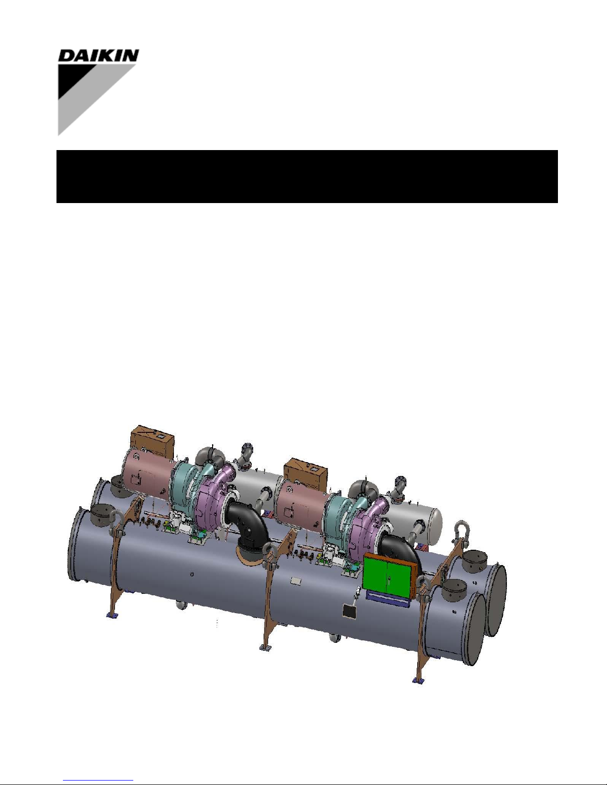
Installation, Operation and Maintenance Manual
D-EIMWC01308-16EN
WCT
Counter-Flow Centrifugal Chillers with Two-Stage Compressors
2200 to 3250 TONS (7750 to 11400 kW)
Series Counter-Flow with Two-Stage Compressors
4500 to 6400 TONS (15830 to 22500 kW)
HFC - 134a
Original Instructions
Page 2

Table of Contents
Safety Instructions ........................................................................................... 4
Introduction ..................................................................................................... 6
Installation ....................................................................................................... 8
Receiving and Handling ....................................................................................................... 8
Rigging ................................................................................................................................ . 9
Location and Mounting ...................................................................................................... 10
System Water Volume ........................................................................................................ 11
Low Condenser Water Temperature Operation (Needs to be updated) .............................. 11
Water Piping ....................................................................................................................... 12
Thermal Insulation ............................................................................................................. 14
Weights and Dimensions ............................................................................... 17
Relief Valves ...................................................................................................................... 25
Electrical ......................................................................................................... 28
Control Power Wiring ........................................................................................................ 29
Field Wiring Diagram ........................................................................................................ 31
Prestart System Checklist ................................................................................ 33
Important information regarding the refrigerant used ............................. 34
D-EIMWC01308-16EN - 2/40
Page 3
WARNING
Before starting the installation of the unit, please read this manual carefully. Starting up the unit is
absolutely forbidden if all instructions contained in this manual are not clear.
WARNING
All installation and maintenance activities must be carried out in compliance with local laws and
regulations.
CAUTION
All units are delivered from the factory complete with wiring diagrams and dimensional drawings
including size and weight for each model.
WIRING DIAGRAMS AND DIMENSIONAL DRAWINGS MUST BE CONSIDERED ESSENTIAL
DOCUMENTS OF THIS MANUAL.
In case of any discrepancy between this manual and the equipment’s document please refer to the
wiring diagram and dimensional drawings.
NOTE
This Manual is a technical aid and does not represent a binding offer for Daikin.
Daikin has drawn up this Manual to the best of its knowledge. The content cannot be held as
explicitly or implicitly guaranteed as complete, precise or reliable.
All data and specifications contained herein may be modified without notice. The data
communicated at the moment of the order shall hold firm.
Daikin shall assume no liability whatsoever for any direct or indirect damage, in the widest sense of
the term, ensuing from or connected with the use and/or interpretation of this Manual.
The entire content is protected by Daikin copyright.
!!!
!
Manufactured in an ISO Certified Facility
©2013 Daikin. Illustrations and data cover the Daikin product at the time of publication and we reserve the right to make
changes in design and construction at anytime without notice.
™® The following are trademarks or registered trademarks of their respective companies: BACnet from ASHRAE; LONMARK,
LonTalk, LONWORKS, and the LONMARK logo are managed, granted and used by LONMARK International under a license granted
by Echelon Corporation; Modbus from Schneider Electric; MicroTech II from Daikin.
.
D-EIMWC01308-16EN - 3/40
Page 4
Safety Instructions
DANGER
Dangers indicate a hazardous situation which will result in death or serious injury if not
avoided.
WARNING
Warnings indicate potentially hazardous situations, which can result in property damage,
severe personal injury, or death if not avoided.
CAUTION
Cautions indicate potentially hazardous situations, which can result in personal injury or
equipment damage if not avoided.
NOTE
Important information used to obtain best results
!!!
!
The following recommendations should be carefully observed as part of installation, operation, maintenance or
service.
This equipment must be installed by trained and qualified personnel experienced in the installation of
similar centrifugal chillers.
This manual contains important information on operation, safety, maintenance, installation, service and
warranty.
Prior to performing any task on this equipment, the information in this manual and any other referenced
material must be carefully read and understood.
Cautions and Warnings
At several points in the manual, items of special interest or significant impact are highlighted by one of the
following notices.
D-EIMWC01308-16EN - 4/40
Page 5
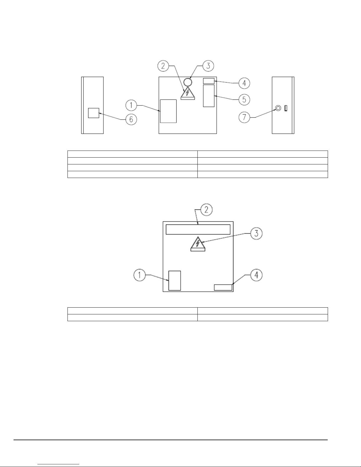
1 – Non flammable gas symbol
6 – Unit characteristics technical
2 – Electrical hazard symbol
5 – Unit nameplate data
3 – Gas type
7 – Emergency stop
4 – Control panel code
1 – Terminal box fixing
3 – Electrical hazard symbol
2 – Manufacturer’s logo
4 – Terminal connection
Description of the labels applied to the electrical panel
Unit Control Panel
Motor Terminal Box
D-EIMWC01308-16EN - 5/40
Page 6

Introduction
Note: See Operating and Maintenance Manual OMM 1194 for information on operating and maintaining
the chiller. A copy can be obtained from www.Daikineurope.com.
General Description
The Daikin Two-Stage Dual Centrifugal Compressor Water Chillers (WCT) are complete, self-
contained, automatically controlled fluid chilling units. Each unit is completely assembled and factory
tested before shipment. These chillers have a separate refrigerant circuit for each compressor. They
are available in single pass arrangement only. They provide the high full load efficiency advantage of
two separate chillers arranged for counter flow operation in a single, compact unit.
The Daikin Model WCT Chillers use 2-stage compressors and provide cooling capacity from 2200 tons
(7750 kW) to 3250 tons (11400 kW) depending on operating conditions in each chiller, which comes up
5000-6000TR system capacity when chiller installs in series counter-flow configuration. In the WCT
series, each unit has two compressors and two economizers connected to a single condenser, and an
evaporator. Each condenser and evaporator has two separate refrigerant circuits.
WCT chiller is suitably designed for series counter-flow, which two WCT unit is connecting in series
and work as one chiller.
The driveline of the WCT is made up of two two-stage compressors, each with a gear set and a 2-
pole, induction semi-hermetic motor.
The controls are pre-wired, adjusted and tested. Only normal field connections such as water and
relief valve piping, electrical and interlocks, etc. are required, thereby simplifying installation and
increasing reliability. Most of the necessary equipment protection and operating controls are factory
installed in the control panel.
Application
Daikin WCT centrifugal chillers are factory tested prior to shipment and must be initially started at
the job site by a factory-trained Daikin authorized technician. Failure to follow this startup procedure
can affect the equipment warranty.
Cooling towers used with Daikin centrifugal chillers are normally selected for maximum condenser
inlet water temperatures between 75°F and 95°F (24°C and 35°C). Lower entering water
temperatures are desirable from the standpoint of energy reduction, but a minimum does exist. See
page10 for recommendations on optimum entering water temperature and cooling tower fan control.
D-EIMWC01308-16EN - 6/40
Page 7
Compressor
(No.1)
Evaporator
Compressor
(No.2)
Condenser
Refrigerant
Nomenclature
WCTKDCCCP2Z / KDCCCP2Z / E5426-BG-1LL / C5426-BR-1LL /134
WCT : Water Cooled Two-Stage Centrifugal
COMPRESSOR
K : Frame Type of Compressor
D : Shroud Pattern of 1st Stage Impeller
C : Impeller Head of 1st Stage Impeller
C : Shroud Pattern of 2nd Stage Impeller
C : Impeller Head of 2nd Stage Impeller
P2 : Motor Rating ( kW )
Z : Voltage ( V ) and Frequency ( Hz )
EVAPORATOR
E5426 : Evaporator Diameter (in) and Length (ft)
B : Tube Count
G : Tube Type
1 : Number of Passes
L : Water Inlet Nozzle Location (R = Right Inlet ; L= Left Inlet)
L : Nozzle Configuration
CONDENSER
C5426 : Condenser Diameter (in) and Length (ft)
B : Tube Count
R : Tube Type
1 : Number of Passes
L : Water Inlet Nozzle Location (R = Right Inlet ; L= Left Inlet)
L : Nozzle Configuration
REFRIGERANT
134 : Refrigerant Type ( 134 = HFC-134a ); WCT is for R134a only.
D-EIMWC01308-16EN - 7/40
Page 8
Installation
NOTE
Chilled water and condenser connection location can vary. Check markings on unit and
consult unit certified drawings for connection locations on specific units.
!
CONDENSER
Circuit 2
UNIT MONITOR
EVAPORATOR
Circuit 1
CONTROL BOX
ECONOMIZER
Circuit 2
EVAPORATOR
Circuit 2
CONDENSER
Circuit 1
ECONOMIZER
Circuit 1
COMPRESSOR
Circuit 2
COMPRESSOR
Circuit 1
Receiving and Handling
The unit should be inspected immediately after receipt for possible damage.
All Daikin centrifugal water chillers are shipped ex-factory and all claims for handling and shipping
damage are the responsibility of the consignee.
Insulation corners from the evaporator's rigging hole locations are shipped loose and should be glued in
place after the unit is finally placed. Neoprene vibration pads are also shipped loose. Check that these
items have been delivered with the unit.
If so equipped, leave the shipping skid in place until the unit is in its final position. This will aid in
handling the equipment.
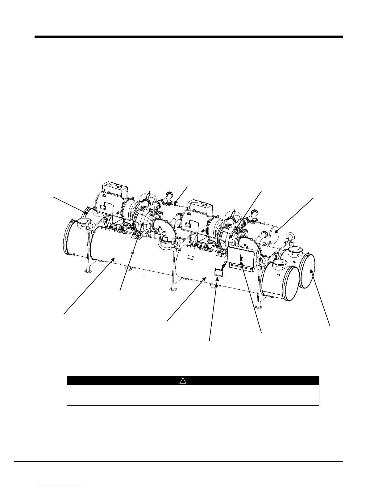
Figure 1, WCT Major Component Locations
Note: Evaporator nozzles may be side-by-side or over-and-under depending on model.
D-EIMWC01308-16EN - 8/40
Page 9
Rigging
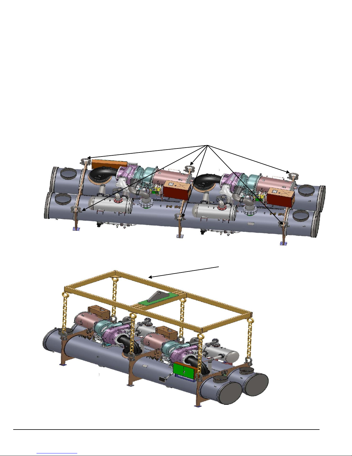
6 Lifting Locations
Lifting Halo Shown for Reference Only
Extreme care must be used when rigging the equipment to prevent damage to the control panels or
refrigerant piping. See the certified dimension drawings included in the job submittal for the center of
gravity of the unit. Consult the local Daikin sales office for assistance if the drawings are not available.
The unit can be lifted by fastening the rigging shackles to the six corners of the unit where the rigging eyes
are located. It is highly recommended the unit be picked up using all 6 lifting locations (see Figure 3) and
the lifting be done with the load at all six locations being vertically up and not at an angle to prevent
possible damage to the control panel, piping, motor terminal box and tubesheets. Lift only using locations
shown in Figure 2. Recommended type of shackle is 50 Ton B.S. 3032 by Van Beest or equal.
If optional shipping skids are used, remove them before lowering the unit to its mounting position. Rig the
unit to its final location on the floor or mounting pad by lifting the unit (or shell assembly) with an
overhead lift and lower the unit to its mounting position.
Figure 2, Rigging Locations
Figure 3, Unit Rigging
D-EIMWC01308-16EN - 9/40
Page 10
Location and Mounting
NOTE
Units will be shipped with holding refrigerant charge and oil. All valves must remain open
until start-up by the authorized commissioning technician.
!
The unit must be mounted on a concrete or steel base which is level end-to-end to within ¼” (6.4 mm) and must
be located to provide service clearance at one end of the unit for possible removal and replacement of evaporator
and/or condenser tubes, and if necessary, to permit brush cleaning of evaporator and condenser tubes as
required. Doors, removable wall sections and piping should be arranged for ease of disassembly at the chiller for
tube clearance and cleaning. Minimum clearance at all other points, including the top, is 3 feet (1 meter). Local
regulation can require more clearance in and around electrical components and must be checked. These chillers
are intended only for installation in an indoor or weather protected area consistent with the NEMA 1 rating on
the chiller, controls, and electrical panels. Equipment room temperature for operating and standby conditions is
40°F to 104°F (4.4°C to 40°C) for storage at higher temperatures refrigerant may need to be removed.
Vibration Pads
The unit is shipped with neoprene vibration pads having a nominal 0.375 inch (9.5 mm) operating height. They
are to be placed under the steel foot supports for contact with the foundation, and to be flush with the sides and
outside edge of the foot supports affixed to the chiller tube sheets.
Mounting
Make sure that the floor or structural support is adequate to support the full operating weight of the complete
unit.
The pads should be located in accordance with the unit dimensional drawing. After the pads have been placed
into position on the floor, lower the unit onto the pads which are to be centered under the foot supports. When
the unit is in place, remove the rigging equipment and check that the chiller is level, both longitudinally and
transversely.
First, check the longitudinal alignment of the unit by placing a “level gage” at top center of the evaporator shell
which has more compressor/motor load. Second, check the transverse alignment by placing a level gage on top
of the tube sheets at both ends of the unit. Their alignment should be within ¼” (6.4 mm) and if not, lift the unit
and place shims between the neoprene pads and the foot supports.
It is not necessary to bolt the unit to the mounting slab but should this be desirable, 1-1/8" (28.5 mm) mounting
holes are provided in the unit feet. See dimension drawing for location.
Each pad deflection is around 0.06 inch (2 mm) and if necessary, shims should be placed between the unit foot
supports and pads to equally deflect all pads.
D-EIMWC01308-16EN - 10/40
Page 11

Nameplates
There are several identification nameplates on the chiller:
The unit nameplate is located on the side of the Unit Control Panel. It has a Style No. XXXX,
Model No. XXXX and Serial No. XXXX. These numbers are unique to the unit and should be used
to identify the unit for service, parts, or warranty questions. This plate also lists the unit operating
refrigerant charge.
Vessel nameplates are located on the evaporator, economizer and condenser. Along with other
information, they have a National Board Number (NB) and a vessel serial number, either of which
identify the vessel (but not the entire unit).
A compressor nameplate is located on the compressor itself and contains identification numbers.
System Water Volume
All chilled water systems need adequate time to recognize a load change, respond to that load change
and stabilize, without undesirable short cycling of the compressors or loss of temperature control. In air
conditioning systems, the potential for short cycling usually exists when the building load falls below
the minimum chiller plant capacity or on close-coupled systems with very small water volumes or due to
improperly operating system controls.
Some of the things the designer should consider when looking at water volume are the minimum cooling
load, the minimum chiller plant capacity during the low load period and the desired cycle time for the
compressors.
Assuming that there are no sudden load changes and that the chiller plant has reasonable turndown, a
rule of thumb of “gallons of water volume equal to two to three times the chilled water gpm flow rate” is
often used.
A properly designed storage tank should be added if the system components do not provide sufficient
water volume.
Low Condenser Water Temperature Operation (Needs to be updated)
When the ambient wet bulb temperature is lower than design, the condenser water temperature can be
allowed to fall. The resultant lower condensing temperature will improve chiller performance.
WCT chillers are equipped with electronic expansion valves (EEV) and will operate with entering
condenser water temperatures as low as calculated by the following equation and shown in the chart
following.
Note: Provisions or modifications need to be made in the event of inverted starts (condenser water
colder than chilled water). For example, 3 way bypass valve controlled by the chiller, or tower controls.
Min. ECWT = 10.973 + LCHWT – 0.17 * CHWDT
ECWT = Entering condenser water temperature
LCHWT = Leaving chilled water temperature
CHWDTFL = Chilled Water Delta-T at full load
PLD = The percent chiller load point to be checked
(PLD/100) + 8 * (PLD/100)2
FL
D-EIMWC01308-16EN - 11/40
Page 12
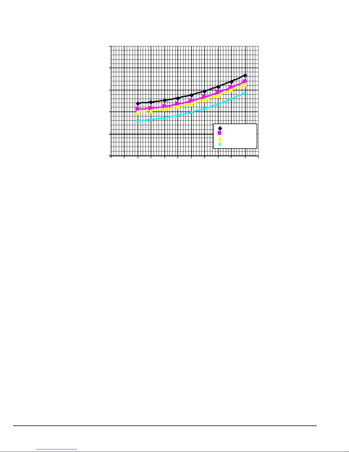
Figure 4, Minimum Operating Entering Condenser Water Temperature (10F Range)
45.00
50.00
55.00
60.00
65.00
70.00
0 10 20 30 40 50 60 70 80 90 100 110
Percent Load
ECWT, (F)
46.0 F LCHWT
44.6 F LCHWT
44.0 F LCHWT
42.0 F LCHWT
Note : Some limitation in control may apply when operating chiller in the condition that ECWT is
same or above but still around minimum ECWT.
For example; at 44F LCHWT, 10-degree F chilled water Delta-T, and 50% full load operation, the
entering condenser water temperature could be as low as 56 F.
The operating strategy for cooling tower fans requires some analysis. Regardless of power consumption
considerations, the minimum allowable entering condenser water temperature must be maintained.
Depending on local climatic conditions, using the lowest possible entering condenser water temperature
may be more costly in total system power consumed than the expected savings in chiller power would
suggest, due to the excessive fan power required.
Even with tower fan control, some form of water flow control, such as tower bypass, is recommended
and is required if fan control alone will not maintain minimum water temperatures.
For cold weather operation, the bypass valve and piping is required and should be inside the building.
Water Piping
Water Pumps
Avoid the use of two-pole pump motors. It is not uncommon to find that these pumps operate with
objectionable noise and vibration.
It is also possible to build up a frequency beat due to the slight difference in the operating rpm of the
pump motor and the Daikin centrifugal motor. Daikin encourages the use of four-pole pump motors.
Both the condenser and chilled water pumps’ discharge connections should be located to supply water
through the chiller at positive pressure.
In cases where the water pump noise can be objectionable, vibration isolation sections are recommended
at both the inlet and outlet of the pump. In most cases, it will not be necessary to provide vibration
D-EIMWC01308-16EN - 12/40
Page 13

eliminator sections in the condenser inlet and outlet water piping. But they can be required where noise
and vibration are critical or if spring isolators are used.
Vessel Drains at Start-up
Unit vessels are equipped with ball-type drain valves in the bottom of each head chamber and shipped
with the valves open. Be sure to close the valves prior to filling the vessels with fluid.
Draining Vessels
If the chiller can be subject to freezing temperatures (possibly when stored prior to installation), the
condenser and evaporator must be drained of all water. Dry air blown through them will aid in forcing
all water out. Removal of condenser heads is also recommended. The condenser and evaporator are not
self-draining and tubes must be blown out. Water permitted to remain in the piping and vessels can
rupture these parts if subjected to freezing temperature and cause corrosion.
Evaporator and Condenser Water Piping
Be sure that water inlet and outlet connections match certified drawings and stenciled nozzle markings.
The tower water supply connection is always the bottom connection of the condenser to maximize
refrigerant sub cooling.
All evaporators and condensers come with optional flange connections or standard Victaulic groove
water nozzles (also suitable for welding). Since the companion flanges, bolts, nuts and gaskets are not
included, the installing contractor must provide matching mechanical connections or transitions of the
size and type required.
If welding is to be performed on the mechanical or flange connections, remove the solid-state
temperature sensor and thermostat bulbs from the wells to prevent damage to those components. Also
properly ground the unit or severe damage to the MicroTech unit controller can occur.
Water pressure gauge connection taps and gauges must be provided in the field piping at the inlet and
outlet connections of both vessels for measuring the water pressure drops. The pressure drops and flow
rates for the various evaporators and condensers are job specific and the original job documentation can
be consulted for this information. Refer to the unit nameplate on the control panel for identification. The
piping should also include thermometers at the inlet and outlet connections and air vents at the high
points.
The piping must be installed and supported to eliminate weight and strain on the fittings and
connections. Cold piping must also be adequately insulated. All water piping should be thoroughly
cleaned of dirt and debris before being connected to the chiller. A cleanable 20-mesh water strainer must
be installed in both water inlet lines as close as possible to the vessels. The strainer will attempt to retain
any possible dirt/debris coming from the cooling tower, deterioration of piping, or from water source
entering the chiller tubes. This can result in a reduction of flow and subsequent reduction of chiller
performance or tube freezing.
Water Flow Sensors
Temperature-based (thermal dispersion) flow sensors are factory mounted in the evaporator and
condenser inlet water nozzles and are factory wired to the control panel. The sensor tip houses
thermistors and a heating element that when power is applied, heats the tip of the probe. How fast the
heat is carried away from the sensor tip by the water flow is detected by the thermistors and they
provide an output when the flow rate falls below the setpoint. This indicates whether there is an
adequate water flow to the vessels before the unit can start. They also serve to shut down the unit in the
event that water flow is interrupted to guard against evaporator freeze-up or excessive discharge
pressure.
D-EIMWC01308-16EN - 13/40
Page 14
Cooling Towers
Evaporator Code
Insulation Area Sq. Ft. (m2)
E4824
840 (78)
E4826
915 (85)
E5424
935 (87)
E5426
1025 (95)
Check the condenser water flow rate to be sure that it conforms to the system design. Some form of
temperature control is also required if an uncontrolled tower can supply water below about 65F (18C).
A tower bypass valve is recommended. Unless the system and the chiller unit are specifically designed
for condenser bypass or variable condenser flow, it is not recommended, since low condenser flow rates
can cause unstable operation and excessive tube fouling.
The condenser water pumps must cycle on and off with the unit. Controlling the pumps with the unit
MicroTech controller is an easy way to accomplish this and is highly recommended. See Figure 8, Field
Wiring Diagram on page 21 for wiring details.
The quality of the water to both the condenser and evaporator should be analyzed by a water treatment
specialist. If not available in-house, competent water treatment specialists can be contracted. Water
treatment is essential for continued efficient and reliable chiller operation. Chiller performance can be
degraded by poor water quality due to rust, sludge, corrosion, mineral deposits, sedimentation, organic
growth etc. Proper chiller performance can be maintained by corrective water treatment when and if
necessary, and periodic cleaning of tubes. If fouling or contaminants may become an issue then it may
be necessary to allow a larger fouling factor for the chiller provided, and/or specific construction
materials for the job site.
Thermal Insulation
Insulation of cold surfaces is required to prevent condensation. These surfaces include the evaporator,
economizer, evaporator water heads and nozzles, suction piping, motor housing, oil cooler refrigerant
supply and return, economizer gas line, expansion valve, piping between economizer and evaporator and
the motor drain line.
Optional factory installed insulation is available in ¾- inch (19 mm) and 1 ½-inch (38 mm) thickness. It
is UL recognized (File # E55475) ABS/PVC flexible foam with a skin. The K factor is 0.28 BTU/hr x
F x sq ft (W/m2 x C) at 75°F (23.9C). Sheet insulation is fitted and cemented in place forming a
vapor barrier and then painted with a resilient finish that resists cracking. Double insulation is available
as an option.
The insulation complies to, or has been tested in accordance, with the following:
ASTM-C-177 ASTM-C-534 Type 2 UL 94-5V
ASTM-D-1056-91-2C1 ASTM E 84 MEA 186-86-M Vol. N
CAN/ULC S102-M88
In the event insulation is to be field-installed, none of the cold surfaces identified above will be factory
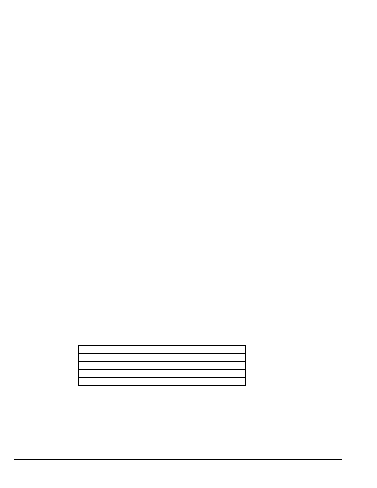
insulated. Required field insulation is shown beginning on page 14. Approximate total square footage of
insulation surface required for individual packaged chillers is tabulated by evaporator code and can be
found below.
Table 1, Evaporator insulation Surface (approx.)
Note : Includes Shell, Tube Sheets and Tube Heads
D-EIMWC01308-16EN - 14/40
Page 15
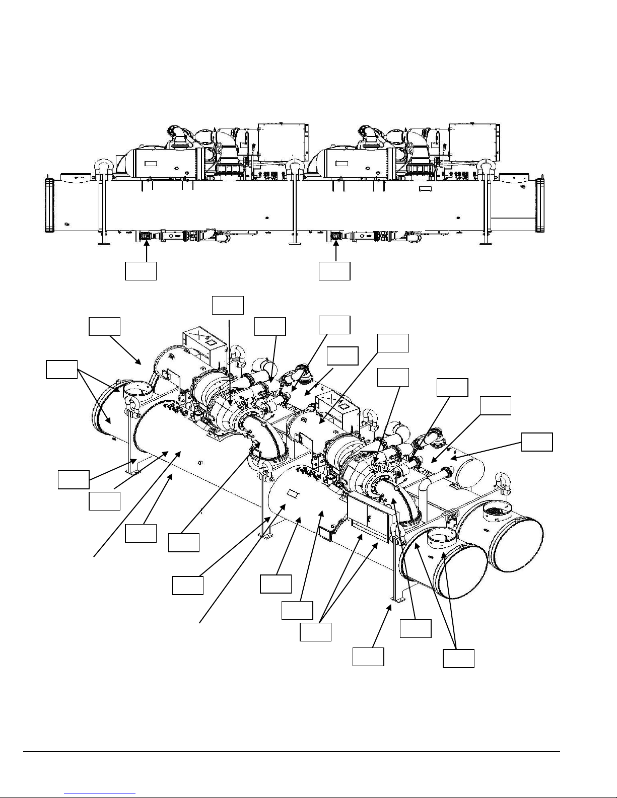
Field Insulation Guide
ISOMETRIC VIEW
CONDENSER
Circuit 2
CONDENSER
Circuit 1
002
001
002
001
003
003
EVAPORATOR
Circuit 1
EVAPORATOR
Circuit 2
005
005
006
006
008
008
009
009
010
010
011
012
012
004
007
007
BACK VIEW
013
013
Figure 5, Insulation Requirements (Bubble components require insulation)
D-EIMWC01308-16EN - 15/40
Page 16
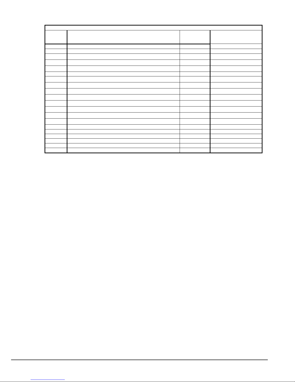
Table 2, Insulated Parts Description
INSULATED PARTS
BUB.
NO.
DESCRIPTION
THICKNESS
( Depend on
Customer)
Probable Surface
Temperature in Rating
Operation USE SHEET INSULATION
001
MOTOR BARREL- BACK PLATE TO GEAR HOUSING
0.75”
36 – 45 oF ( 2 – 7 oC )
002
EVAPORATOR SHELL- TUBESHEET TO TUBESHEET
0.75”
36 – 45 oF ( 2 – 7 oC )
003
NOZZLE HEAD & NOZZLE TO BACK OF FLANGE
0.75”
36 – 45 oF ( 2 – 7 oC )
004
EVAPORATOR MIDDLE TUBE SHEET
0.75”
36 – 45 oF ( 2 – 7 oC )
005
ECONOMIZER- HEAD TO HEAD AND NOZZLES
0.75”
59 – 77 oF ( 15 – 25 oC )
006
ECONOMIZER GAS LINE
0.75”
59 – 77 oF ( 15 – 25 oC )
007
EXPANSION VALVE TO ECONOMIZER
0.75”
59 – 77 oF ( 15 – 25 oC )
008
ALL PIPING LEAVING ECONOMIZER TO EVAPORATOR
0.75”
36 – 45 oF ( 2 – 7 oC )
009
SUCTION LINE- COMPRESSOR TO EVAPORATOR
0.75”
36 – 45 oF ( 2 – 7 oC )
010
EVAPORATOR END TUBESHEETS
0.75”
36 – 45 oF ( 2 – 7 oC )
011
BOTH SIDES OF BRACKETS TO BOTTOM OF WIREWAY
0.75”
36 – 45 oF ( 2 – 7 oC )
012
FRONT END OF COMPRESSOR
0.75”
36 – 45 oF ( 2 – 7 oC )
013
CAP SIGHT GLASSES ON EVAP
0.75”
36 – 45 oF ( 2 – 7 oC )
USE TUBE INSULATION
OIL COOLER SUPPLY LINE (1.125 ID)
OIL COOLER RETURN LINE (1.125 ID)
MOTOR DRAIN (.375 ID)
EDUCTOR LINE-FROM EVAP. TO OIL SUMP (0.375 id)
.
D-EIMWC01308-16EN - 16/40
Page 17
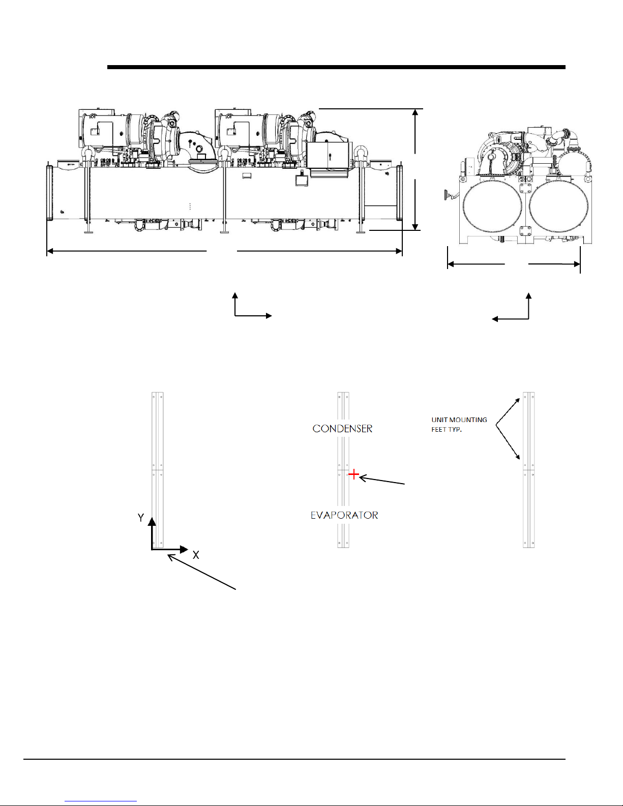
Weights and Dimensions
A
B
Y(+)
Z(+)
X(+)
Y(+)
C
CENTER OF
GRAVITY
(0, 0, 0)
ORIGIN OF COORDINATES
(Bottom-left corner of evaporator feet
opposite to compressor suction)
Figure 6, Unit Overall Dimensions
Figure 7, Unit Mounting Feet, Top Sectional View
(Position of Center of Gravity relative to (0,0,0) changes depending on Unit Size)
D-EIMWC01308-16EN - 17/40
Page 18
D-EIMWC01308-16EN - 18/40
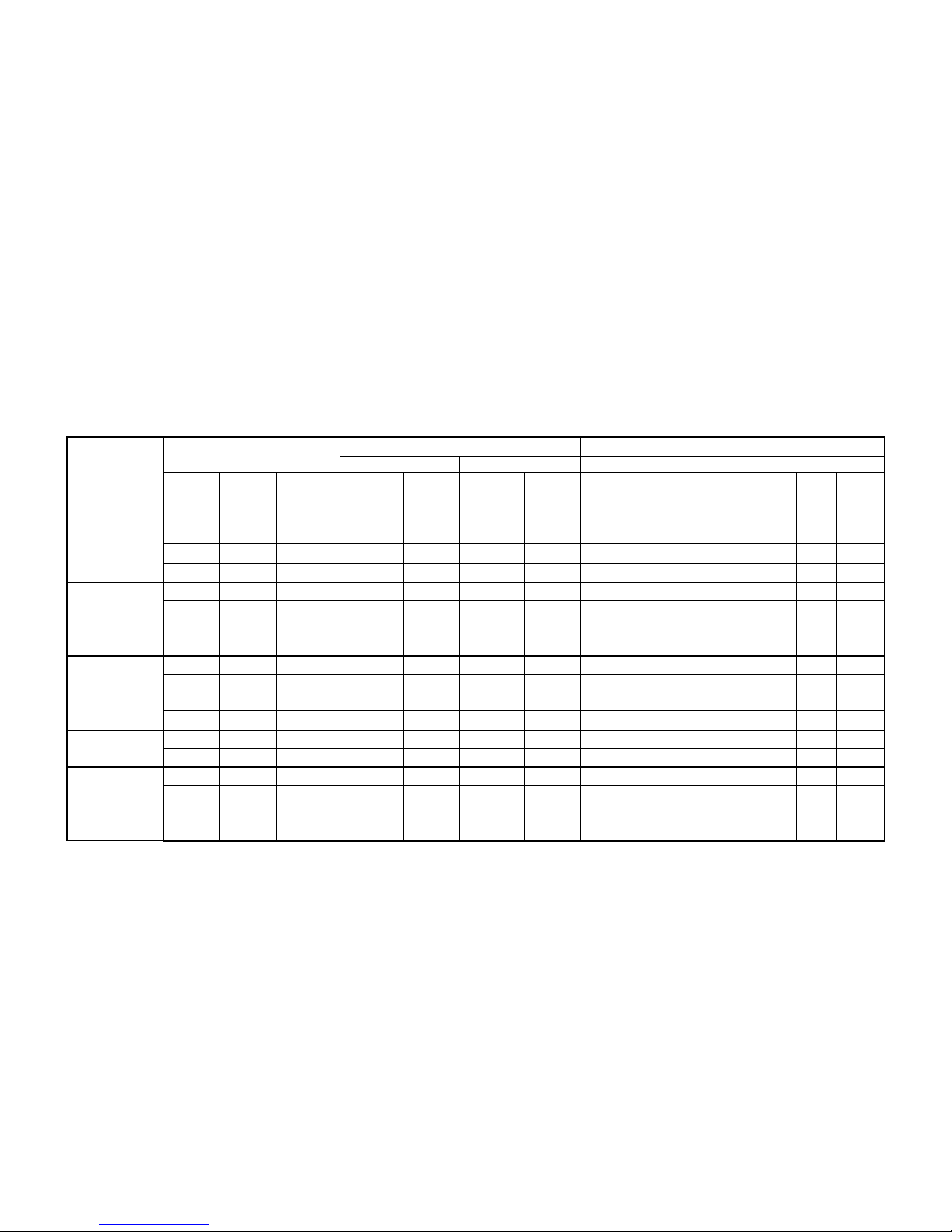
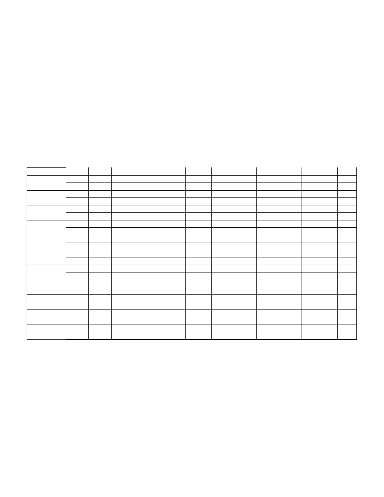
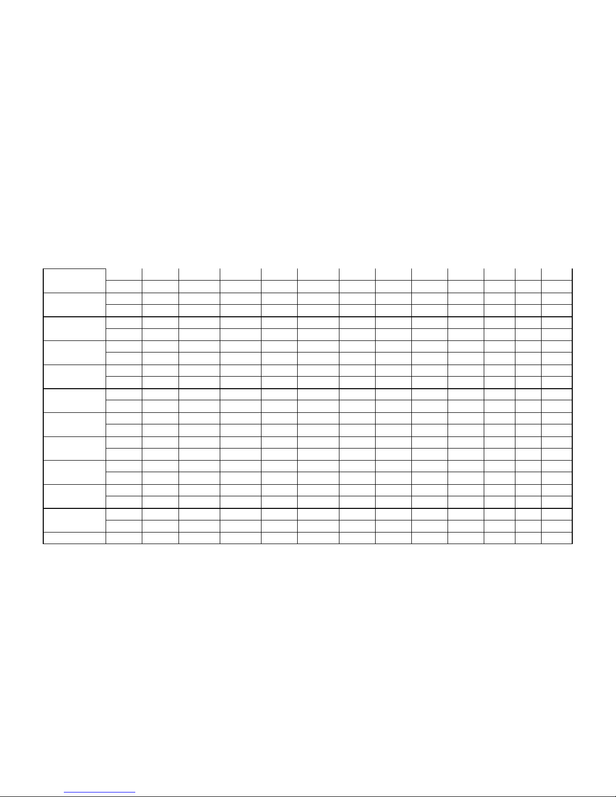
Table 3, Weights and Dimensions
Shells
Approximated Weights per Chiller
Approximated Water Volumes per Chiller
Overall Dimensions
Condenser
Evaporator
Unit
COG (OPERATING)
Shipping
Weight
Operating
Weight
Refrigerant
Charge
Water
volume of
water
boxes
(including
nozzles)
Total
water
volume
Water
volume of
water
boxes
(including
nozzles)
Total
water
volume
A'
Overall
length
B'
Overall
Height
C'
Overall
width
X Y Z
lb
lb
lb
gal
gal
gal
gal
in
in
In
in
in
in
kg
kg
kg l l l l
mm
mm
mm
mm
mm
mm
C4224-B/E4824-B
81'600
108'100
6'250
470
1'190
580
1'060
371
125
124
142
62
52
(36'900)
(48'900)
(2'900)
(1'790)
(4'570)
(2'220)
(4'060)
(9'436)
(3'167)
(3'148)
(3'611)
(1'575)
(1'323)
C4224-B/E4824-C
81'300
107'600
6'550
470
1'190
580
1'010
371
125
124
142
62
52
(36'800)
(48'600)
(3'000)
(1'790)
(4'570)
(2'220)
(3'880)
(9'436)
(3'167)
(3'148)
(3'610)
(1'580)
(1'326)
C4224-B/E4824-D
81'100
106'800
6'850
470
1'190
580
960
371
125
124
142
62
52
(36'700)
(48'300)
(3'100)
(1'790)
(4'570)
(2'220)
(3'700)
(9'436)
(3'167)
(3'148)
(3'610)
(1'585)
(1'329)
C4224-C/E4824-B
81'500
107'900
6'250
470
1'120
580
1'060
371
125
124
142
62
52
(36'900)
(48'800)
(2'900)
(1'790)
(4'290)
(2'220)
(4'060)
(9'436)
(3'167)
(3'148)
(3'604)
(1'570)
(1'323)
C4224-C/E4824-C
81'300
107'700
6'550
470
1'120
580
1'010
371
125
124
142
62
52
(36'800)
(48'700)
(3'000)
(1'790)
(4'290)
(2'220)
(3'880)
(9'436)
(3'167)
(3'148)
(3'607)
(1'575)
(1'327)
C4224-C/E4824-D
81'000
106'700
6'850
470
1'120
580
960
371
125
124
142
62
52
(36'600)
(48'300)
(3'100)
(1'790)
(4'290)
(2'220)
(3'700)
(9'436)
(3'167)
(3'148)
(3'601)
(1'580)
(1'330)
C4224-D/E4824-B
81'400
107'700
6'250
470
1'050
580
1'060
371
125
124
142
62
52
(36'800)
(48'700)
(2'900)
(1'790)
(4'040)
(2'220)
(4'060)
(9'436)
(3'167)
(3'148)
(3'602)
(1'565)
(1'324)
Page 19
D-EIMWC01308-16EN - 19/40
C4224-D/E4824-C
81'100
107'200
6'550
470
1'050
580
1'010
371
125
124
142
62
52
(36'700)
(48'500)
(3'000)
(1'790)
(4'040)
(2'220)
(3'880)
(9'436)
(3'167)
(3'148)
(3'601)
(1'570)
(1'327)
C4224-D/E4824-D
80'800
106'600
6'850
470
1'050
580
960
135
125
124
142
62
52
(36'600)
(48'200)
(3'100)
(1'790)
(4'040)
(2'220)
(3'700)
(3'436)
(3'167)
(3'148)
(3'601)
(1'575)
(1'331)
C4226-B/E4826-B
85'600
110'200
6'650
470
1'250
580
1'100
396
125
124
158
60
52
(38'700)
(49'800)
(3'100)
(1'790)
(4'800)
(2'220)
(4'220)
(10'058)
(3'167)
(3'148)
(4'018)
(1'528)
(1'321)
C4226-B/E4826-C
85'000
109'600
6'950
470
1'250
580
1'050
396
125
124
158
60
52
(38'400)
(49'600)
(3'200)
(1'790)
(4'800)
(2'220)
(4'020)
(10'058)
(3'167)
(3'148)
(4'018)
(1'534)
(1'325)
C4226-B/E4826-D
84'400
109'100
7'300
470
1'250
580
1'000
396
125
124
158
61
52
(38'200)
(49'300)
(3'300)
(1'790)
(4'800)
(2'220)
(3'820)
(10'058)
(3'167)
(3'148)
(4'018)
(1'540)
(1'326)
C4226-C/E4826-B
93'300
108'900
6'650
470
1'170
580
1'100
396
125
124
158
60
52
(42'200)
(49'200)
(3'100)
(1'790)
(4'500)
(2'220)
(4'220)
(10'058)
(3'167)
(3'148)
(4'018)
(1'516)
(1'324)
C4226-C/E4826-C
92'500
108'300
6'950
470
1'170
580
1'050
396
125
124
158
60
52
(41'800)
(49'000)
(3'200)
(1'790)
(4'500)
(2'220)
(4'020)
(10'058)
(3'167)
(3'148)
(4'018)
(1'522)
(1'325)
C4226-C/E4826-D
91'100
107'800
7'300
470
1'170
580
1'000
396
125
124
158
60
52
(41'200)
(48'700)
(3'300)
(1'790)
(4'500)
(2'220)
(3'820)
(10'058)
(3'167)
(3'148)
(4'018)
(1'528)
(1'327)
C4226-D/E4826-B
92'700
107'700
6'650
470
1'100
580
1'100
396
125
124
158
59
52
(41'900)
(48'700)
(3'100)
(1'790)
(4'230)
(2'220)
(4'220)
(10'058)
(3'167)
(3'148)
(4'018)
(1'505)
(1'324)
C4226-D/E4826-C
91'900
106'300
6'950
470
1'100
580
1'050
396
125
124
158
59
52
(41'600)
(48'100)
(3'200)
(1'790)
(4'230)
(2'220)
(4'020)
(10'058)
(3'167)
(3'148)
(4'018)
(1'511)
(1'328)
C4226-D/E4826-D
91'100
106'600
7'300
470
1'100
580
1'000
396
125
124
158
60
52
(41'200)
(48'200)
(3'300)
(1'790)
(4'230)
(2'220)
(3'820)
(10'058)
(3'167)
(3'148)
(4'018)
(1'517)
(1'325)
Page 20
D-EIMWC01308-16EN - 20/40
C4824-B/E4824-B
91'400
110'000
6'500
570
1'490
580
1'060
371
125
130
142
68
52
(41'300)
(49'800)
(3'000)
(2'200)
(5'730)
(2'220)
(4'060)
(9'436)
(3'167)
(3'300)
(3'611)
(1'730)
(1'321)
C4824-B/E4824-C
91'000
109'500
6'750
570
1'490
580
1'010
371
125
130
142
68
52
(41'200)
(49'500)
(3'100)
(2'200)
(5'730)
(2'220)
(3'880)
(9'436)
(3'167)
(3'300)
(3'610)
(1'726)
(1'331)
C4824-B/E4824-D
90'700
109'000
7'050
570
1'490
580
960
371
125
130
142
68
53
(41'000)
(49'300)
(3'200)
(2'200)
(5'730)
(2'220)
(3'700)
(9'436)
(3'167)
(3'300)
(3'610)
(1'722)
(1'341)
C4824-C/E4824-B
90'600
108'500
6'500
570
1'400
580
1'060
371
125
130
142
68
52
(41'000)
(49'100)
(3'000)
(2'200)
(5'380)
(2'220)
(4'060)
(9'436)
(3'167)
(3'300)
(3'604)
(1'730)
(1'321)
C4824-C/E4824-C
90'300
108'000
6'750
570
1'400
580
1'010
371
125
130
142
68
52
(40'800)
(48'800)
(3'100)
(2'200)
(5'380)
(2'220)
(3'880)
(9'436)
(3'167)
(3'300)
(3'607)
(1'726)
(1'331)
C4824-C/E4824-D
89'900
107'400
7'050
570
1'400
580
960
371
125
130
142
68
53
(40'700)
(48'600)
(3'200)
(2'200)
(5'380)
(2'220)
(3'700)
(9'436)
(3'167)
(3'300)
(3'601)
(1'722)
(1'341)
C4824-D/E4824-B
89'900
106'900
6'500
570
1'310
580
1'060
371
125
130
142
68
52
(40'600)
(48'400)
(3'000)
(2'200)
(5'020)
(2'220)
(4'060)
(9'436)
(3'167)
(3'300)
(3'602)
(1'730)
(1'321)
C4824-D/E4824-C
89'500
106'400
6'750
570
1'310
580
1'010
371
125
130
142
68
52
(40'500)
(48'100)
(3'100)
(2'200)
(5'020)
(2'220)
(3'880)
(9'436)
(3'167)
(3'300)
(3'601)
(1'726)
(1'331)
C4824-D/E4824-D
89'100
105'900
7'050
570
1'310
580
960
371
125
130
142
68
53
(40'300)
(47'900)
(3'200)
(2'200)
(5'020)
(2'220)
(3'700)
(9'436)
(3'167)
(3'300)
(3'601)
(1'722)
(1'341)
C4826-B/E4826-B
93'700
113'700
6'900
570
1'570
580
1'100
396
125
130
158
65
52
(42'400)
(51'400)
(3'200)
(2'200)
(6'030)
(2'220)
(4'220)
(10'058)
(3'167)
(3'300)
(4'018)
(1'641)
(1'322)
C4826-B/E4826-C
93'300
113'200
7'200
570
1'570
580
1'050
396
125
130
158
65
52
(42'200)
(51'200)
(3'300)
(2'200)
(6'030)
(2'220)
(4'020)
(10'058)
(3'167)
(3'300)
(4'018)
(1'648)
(1'328)
C4826-B/E4826-D
92'900
112'600
7'550
570
1'570
580
1'000
396
125
130
158
65
52
Page 21
D-EIMWC01308-16EN - 21/40
(42'000)
(50'900)
(3'400)
(2'200)
(6'030)
(2'220)
(3'820)
(10'058)
(3'167)
(3'300)
(4'018)
(1'655)
(1'329)
C4826-C/E4826-B
92'900
112'000
6'900
570
1'470
580
1'100
396
125
130
158
64
52
(42'000)
(50'700)
(3'200)
(2'200)
(5'640)
(2'220)
(4'220)
(10'058)
(3'167)
(3'300)
(4'018)
(1'628)
(1'321)
C4826-C/E4826-C
92'500
111'500
7'200
570
1'470
580
1'050
396
125
130
158
64
52
(41'800)
(50'400)
(3'300)
(2'200)
(5'640)
(2'220)
(4'020)
(10'058)
(3'167)
(3'300)
(4'018)
(1'635)
(1'331)
C4826-C/E4826-D
92'100
110'900
7'550
570
1'470
580
1'000
396
125
130
158
65
52
(41'700)
(50'200)
(3'400)
(2'200)
(5'640)
(2'220)
(3'820)
(10'058)
(3'167)
(3'300)
(4'018)
(1'642)
(1'327)
C4826-D/E4826-B
92'100
110'800
7'350
570
1'370
580
1'100
396
125
130
158
64
52
(41'700)
(50'100)
(3'400)
(2'200)
(5'260)
(2'220)
(4'220)
(10'058)
(3'167)
(3'300)
(4'018)
(1'615)
(1'321)
C4826-D/E4826-C
91'700
109'800
7'200
570
1'370
580
1'050
396
125
130
158
64
52
(41'500)
(49'700)
(3'300)
(2'200)
(5'260)
(2'220)
(4'020)
(10'058)
(3'167)
(3'300)
(4'018)
(1'621)
(1'331)
C4826-D/E4826-D
91'300
109'300
7'550
570
1'370
580
1'000
396
125
130
158
64
53
(41'300)
(49'400)
(3'400)
(2'200)
(5'260)
(2'220)
(3'820)
(10'058)
(3'167)
(3'300)
(4'018)
(1'628)
(1'340)
C4824-B/E5424-B
95'400
125'000
7'200
570
1'400
730
1'380
371
132
130
142
66
53
(43'100)
(56'500)
(3'300)
(2'200)
(5'380)
(2'780)
(5'310)
(9'436)
(3'362)
(3'300)
(3'611)
(1'668)
(1'357)
C4824-B/E5424-C
94'900
124'300
7'600
570
1'400
730
1'320
371
132
130
142
66
54
(42'900)
(56'200)
(3'500)
(2'200)
(5'380)
(2'780)
(5'060)
(9'436)
(3'362)
(3'300)
(3'610)
(1'677)
(1'361)
C4824-B/E5424-D
94'400
123'600
8'000
570
1'400
730
1'250
371
132
130
142
66
54
(42'700)
(55'900)
(3'600)
(2'200)
(5'380)
(2'780)
(4'800)
(9'436)
(3'362)
(3'300)
(3'610)
(1'685)
(1'366)
C4824-C/E5424-B
94'600
123'500
7'200
570
1'490
730
1'380
371
132
130
142
65
54
(42'800)
(55'800)
(3'300)
(2'200)
(5'730)
(2'780)
(5'310)
(9'436)
(3'362)
(3'300)
(3'604)
(1'657)
(1'362)
C4824-C/E5424-C
94'100
122'800
7'600
570
1'490
730
1'320
371
132
130
142
66
54
(42'600)
(55'500)
(3'500)
(2'200)
(5'730)
(2'780)
(5'060)
(9'436)
(3'362)
(3'300)
(3'607)
(1'665)
(1'367)
Page 22
D-EIMWC01308-16EN - 22/40
C4824-C/E5424-D
93'600
122'000
8'000
570
1'490
730
1'250
371
132
130
142
66
54
(42'300)
(55'200)
(3'600)
(2'200)
(5'730)
(2'780)
(4'800)
(9'436)
(3'362)
(3'300)
(3'601)
(1'674)
(1'372)
C4824-D/E5424-B
93'900
121'900
7'200
570
1'310
730
1'380
371
132
130
142
65
54
(42'500)
(55'100)
(3'300)
(2'200)
(5'020)
(2'780)
(5'310)
(9'436)
(3'362)
(3'300)
(3'602)
(1'645)
(1'368)
C4824-D/E5424-C
93'400
121'200
7'600
570
1'310
730
1'320
371
132
130
142
65
54
(42'200)
(54'800)
(3'500)
(2'200)
(5'020)
(2'780)
(5'060)
(9'436)
(3'362)
(3'300)
(3'601)
(1'654)
(1'373)
C4824-D/E5424-D
92'900
120'500
8'000
570
1'310
730
1'250
371
132
130
142
65
54
(42'000)
(54'500)
(3'600)
(2'200)
(5'020)
(2'780)
(4'800)
(9'436)
(3'362)
(3'300)
(3'601)
(1'662)
(1'378)
C4826-B/E5426-B
97'900
129'000
7'700
570
1'570
730
1'440
396
132
130
158
62
53
(44'300)
(58'400)
(3'500)
(2'200)
(6'030)
(2'780)
(5'520)
(10'058)
(3'362)
(3'300)
(4'018)
(1'585)
(1'345)
C4826-B/E5426-C
97'300
128'300
8'100
570
1'570
730
1'370
396
132
130
158
63
53
(44'000)
(58'000)
(3'700)
(2'200)
(6'030)
(2'780)
(5'250)
(10'058)
(3'362)
(3'300)
(4'018)
(1'593)
(1'350)
C4826-B/E5426-D
96'800
127'500
8'550
570
1'570
730
1'300
396
132
130
158
63
53
(43'800)
(57'700)
(3'900)
(2'200)
(6'030)
(2'780)
(4'970)
(10'058)
(3'362)
(3'300)
(4'018)
(1'601)
(1'354)
C4826-C/E5426-B
97'000
127'400
7'700
570
1'470
730
1'440
396
132
130
158
62
53
(43'900)
(57'600)
(3'500)
(2'200)
(5'640)
(2'780)
(5'520)
(10'058)
(3'362)
(3'300)
(4'018)
(1'572)
(1'350)
C4826-C/E5426-C
96'500
126'600
8'100
570
1'470
730
1'370
396
132
130
158
62
53
(43'600)
(57'300)
(3'700)
(2'200)
(5'640)
(2'780)
(5'250)
(10'058)
(3'362)
(3'300)
(4'018)
(1'580)
(1'355)
C4826-C/E5426-D
96'000
125'800
8'550
570
1'470
730
1'300
396
132
130
158
63
54
(43'400)
(56'900)
(3'900)
(2'200)
(5'640)
(2'780)
(4'970)
(10'058)
(3'362)
(3'300)
(4'018)
(1'588)
(1'360)
C4826-D/E5426-B
96'200
125'700
7'700
570
1'370
730
1'440
396
132
130
158
61
53
(43'500)
(56'800)
(3'500)
(2'200)
(5'260)
(2'780)
(5'520)
(10'058)
(3'362)
(3'300)
(4'018)
(1'558)
(1'356)
C4826-D/E5426-C
95'700
124'900
8'100
570
1'370
730
1'370
396
132
130
158
62
54
Page 23
D-EIMWC01308-16EN - 23/40
(43'300)
(56'500)
(3'700)
(2'200)
(5'260)
(2'780)
(5'250)
(10'058)
(3'362)
(3'300)
(4'018)
(1'566)
(1'361)
C4826-D/E5426-D
95'100
124'200
8'550
570
1'370
730
1'300
396
132
130
158
62
54
(43'000)
(56'200)
(3'900)
(2'200)
(5'260)
(2'780)
(4'970)
(10'058)
(3'362)
(3'300)
(4'018)
(1'575)
(1'366)
C5424-B/E5424-B
100'800
133'100
7'500
720
1'640
730
1'380
371
132
130
142
68
55
(45'600)
(60'200)
(3'400)
(2'750)
(6'280)
(2'780)
(5'310)
(9'436)
(3'362)
(3'300)
(3'611)
(1'721)
(1'387)
C5424-B/E5424-C
100'300
132'400
7'900
720
1'640
730
1'320
371
132
130
142
68
55
(45'300)
(59'900)
(3'600)
(2'750)
(6'280)
(2'780)
(5'060)
(9'436)
(3'362)
(3'300)
(3'610)
(1'730)
(1'391)
C5424-B/E5424-D
99'800
131'700
8'300
720
1'640
730
1'250
371
132
130
142
68
55
(45'100)
(59'600)
(3'800)
(2'750)
(6'280)
(2'780)
(4'800)
(9'436)
(3'362)
(3'300)
(3'610)
(1'738)
(1'395)
C5424-C/E5424-B
99'800
131'100
7'500
720
1'550
730
1'380
371
132
130
142
67
55
(45'100)
(59'300)
(3'400)
(2'750)
(5'930)
(2'780)
(5'310)
(9'436)
(3'362)
(3'300)
(3'604)
(1'708)
(1'394)
C5424-C/E5424-C
99'300
130'400
7'900
720
1'550
730
1'320
371
132
130
142
68
55
(44'900)
(59'000)
(3'600)
(2'750)
(5'930)
(2'780)
(5'060)
(9'436)
(3'362)
(3'300)
(3'607)
(1'716)
(1'398)
C5424-C/E5424-D
98'800
129'700
8'300
720
1'550
730
1'250
371
132
130
142
68
55
(44'700)
(58'600)
(3'800)
(2'750)
(5'930)
(2'780)
(4'800)
(9'436)
(3'362)
(3'300)
(3'601)
(1'725)
(1'402)
C5424-D/E5424-B
98'800
129'100
7'500
720
1'450
730
1'380
371
132
130
142
67
55
(44'700)
(58'400)
(3'400)
(2'750)
(5'570)
(2'780)
(5'310)
(9'436)
(3'362)
(3'300)
(3'602)
(1'695)
(1'400)
C5424-D/E5424-C
98'300
128'400
7'900
720
1'450
730
1'320
371
132
130
142
67
55
(44'400)
(58'100)
(3'600)
(2'750)
(5'570)
(2'780)
(5'060)
(9'436)
(3'362)
(3'300)
(3'601)
(1'703)
(1'404)
C5424-D/E5424-D
97'800
127'700
8'300
720
1'450
730
1'250
371
132
130
142
67
55
(44'200)
(57'700)
(3'800)
(2'750)
(5'570)
(2'780)
(4'800)
(9'436)
(3'362)
(3'300)
(3'601)
(1'712)
(1'409)
C5426-B/E5426-B
110'900
140'300
8'050
720
2'030
730
1'440
396
132
130
158
63
57
(50'200)
(63'500)
(3'700)
(2'750)
(7'790)
(2'780)
(5'520)
(10'058)
(3'362)
(3'300)
(4'020)
(1'604)
(1'460)
Page 24
D-EIMWC01308-16EN - 24/40
C5426-B/E5426-C
104'100
139'300
8'450
720
2'030
730
1'370
396
132
130
158
63
58
(47'100)
(63'000)
(3'900)
(2'750)
(7'790)
(2'780)
(5'250)
(10'058)
(3'362)
(3'300)
(4'019)
(1'610)
(1'467)
C5426-B/E5426-D
103'700
138'100
8'900
720
2'030
730
1'300
396
132
130
158
64
58
(46'900)
(62'500)
(4'100)
(2'750)
(7'790)
(2'780)
(4'970)
(10'058)
(3'362)
(3'300)
(4'019)
(1'616)
(1'471)
C5426-C/E5426-B
103'700
138'300
8'050
720
1'900
730
1'440
396
132
130
158
63
58
(46'900)
(62'600)
(3'700)
(2'750)
(7'290)
(2'780)
(5'520)
(10'058)
(3'362)
(3'300)
(4'019)
(1'591)
(1'464)
C5426-C/E5426-C
103'200
137'300
8'450
720
1'900
730
1'370
396
132
130
158
63
58
(46'700)
(62'100)
(3'900)
(2'750)
(7'290)
(2'780)
(5'250)
(10'058)
(3'362)
(3'300)
(4'019)
(1'597)
(1'471)
C5426-C/E5426-D
102'800
136'200
8'900
720
1'900
730
1'300
396
132
130
158
63
58
(46'500)
(61'600)
(4'100)
(2'750)
(7'290)
(2'780)
(4'970)
(10'058)
(3'362)
(3'300)
(4'019)
(1'604)
(1'474)
C5426-D/E5426-B
102'900
135'500
8'050
720
1'770
730
1'440
396
132
130
158
62
58
(46'500)
(61'300)
(3'700)
(2'750)
(6'780)
(2'780)
(5'520)
(10'058)
(3'362)
(3'300)
(4'019)
(1'573)
(1'471)
C5426-D/E5426-C
102'500
134'400
8'450
720
1'770
730
1'370
396
132
130
158
62
58
(46'300)
(60'800)
(3'900)
(2'750)
(6'780)
(2'780)
(5'250)
(10'058)
(3'362)
(3'300)
(4'018)
(1'579)
(1'478)
C5426-D/E5426-D
102'000
133'700
8'900
720
1'770
730
1'300
396
132
130
158
62
58
(46'100)
(60'500)
(4'100)
(2'750)
(6'780)
(2'780)
(4'970)
(10'058)
(3'362)
(3'300)
(4'018)
(1'585)
(1'482)
Notes:
1. Drawings and data included in this section are for rough layout purposes only. Detailed certified drawings, as .pdf or .dwg files, are available from the local Daikin sales office. Do
not use catalog drawings for final construction
2. These data are for reference only and do not include options (like different tube type) Certified drawing will show data fo r the specific unit.
3. Obtain specific unit certified drawings for detailed dimensions of water, and relief valve connections.
Page 25
CAUTION
When the oil pump operates without any oil or with an insufficient amount of oil, it might
cause vibration and become extremely noisy and pump damage can occur.
WARNING
Comply with local regulations when removing or disposing of refrigerant system oil.
Evaporator Code
Pressure Setting
Min. Required Discharge Capacity
( lb-air/min )
E4824
200 psi
98
E4826
200 psi
105
E5424
200 psi
108
E5426
200 psi
115
!
!
Lubrication System
Emkarate RL68H Polyolester Oil must be used in the centrifugal two-stage compressor. The nominal oil
charge for K compressor is 22 gallons.
An internal oil sump is part of the compressor and contains a 750 W submersible fixed-speed oil pump
and a 1.0 kW immersion-type oil heater that is thermostatically controlled. A pre/adjusted oil pressure
regulator valve located in the pump discharge line controls the proper oil pressure to all bearings, gears,
and rotating parts. The oil pump operates prior to start-up and continuously operates during the chiller
operation and coast down.
Oil is filtered by an externally mounted 10 micron replaceable cartridge oil filter and is cooled via
refrigerant-cooled oil cooler. Sub-cooled refrigerant liquid is provided by a pressure differential between
the condenser and evaporator to the oil cooler. The supply flow of refrigerant to the oil cooler is
regulated with a thermal expansion valve, by monitoring the temperature of oil coming out of the oil
cooler. Refrigerant leaving the oil cooler is then returned back to the evaporator.
The refrigerant and oil side of the oil cooler are provided with service valves for isolation during service.
An eductor-based oil recovery system is part of the chiller circuit. It returns oil-rich refrigerant from the
evaporator to the oil sump for separation and reduces or eliminates oil contamination in the evaporator. A
filter drier is installed at the inlet of the eductor.
Both the oil lubrication piping and oil cooler refrigerant piping are completely factory-installed, thus
eliminating the need for any field piping.
Relief Valves
As a safety precaution and to meet applicable pressure vessel code requirements, each chiller is equipped
with spring-loaded pressure relief valves for the purpose of relieving excessive refrigerant pressure
(caused by equipment malfunction, fire, etc.) as noted on the pressure vessel name plate. The relief valve
should be replaced with a new one whenever such a release occurs.
Table 4, Relief Valve Data per Evaporator Circuit
(sized for combined economizer and evaporator)
Note : Calculations based on using an economizer nominal 30 in OD and 64 in Long
D-EIMWC01308-16EN - 25/40
Page 26
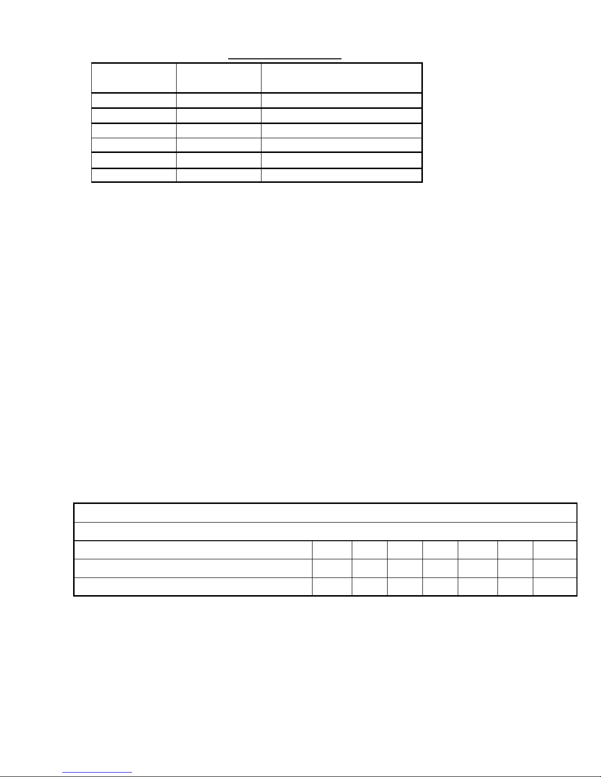
Condenser Code
Pressure Setting
Min. Required Discharge Capacity
( lb-air/min )
C4224
200 psi
67
C4226
200 psi
72
C4824
200 psi
77
C4826
200 psi
83
C5424
200 psi
86
C5426
200 psi
94
Relief Valve Pressure Setting = 200 psig
Rated Relief Valve Capacity = 75.5 lbm air/ min
Nominal Pipe Size ( in )
1-1/4
1-1/2 2 2.5 3 4
5
(I.D.) Internal Diameter of Pipe for Sch. 40
(Note 2)
( in )
1.380
1.610
2.067
2.469
3.068
4.026
5.047
(L) Equivalent Length of Discharge Piping (ft)
4
21
113
313
1,021
4,308
14,113
Table 5, Relief Valve Data per Condenser Circuit
Refrigerant Vent Piping
Codes require that relief valves be vented to the outside of a building, and this is a desirable practice for
all installations. Relief piping connections to the relief valves must have flexible connectors to minimize
strain, as well as vertical drop legs to retain condensation.
Remove plastic shipping plugs (if installed) from the inside of the valves prior to making pipe
connections. Whenever vent piping is installed, the lines must be run in accordance with local code
requirements. Where local codes do not apply, follow the latest issue of ANSI/ASHRAE Standard 15 code
recommendations.
Single Vent Line per Relief Valve
WCT units have relief valve settings of 200 psig and resultant valve discharge capacities of 75.5 lbm
air/min. Using the formulas in ASHRAE Standard 15 defines the maximum length of discharge vent
piping downstream of the pressure relief valve in Table 6.
The ASHRAE 15 User’s Manual provides that, when the length of vent pipe exceeds approximately 220
diameters ( Equivalent Length / Inside Diameter > 220 ), use 0.7848*(L)
relief valve setting of 200 psig, relief valve discharge capacity of 75.5 lbm air/min and average friction
factor of 0.02) in order to compute the approximate internal diameter of the relief valve discharge line if
this diameter is constant for the entire length of pipe. Then compare the calculated internal diameter size
to the values in Table 6, and select a pipe having an inside diameter equivalent or bigger than the required
internal diameter using standard schedule 40 pipe.
0.2
(this equation is only true for
Table 6, Maximum Lengths of vent piping per relief valve vented to atmosphere.
Notes:
1) This table is to be used only as a guideline for estimating and is subject to changes made in Standard ASHRAE 15
or overriding local code.
2) Sch 40 Pipe size used for an example only.
D-EIMWC01308-16EN - 26/40
Page 27

Common Header Vent Line
When valves are piped together, the common piping must follow the rules according to ASHRAE
Standard 15. The minimum line size of a common header application is based on the sum of the relief
valve discharge areas and the sum of the rated discharge capacities. The discharge from more than one
relief valve can be run into a common header, the area of which cannot be less than the sum of the areas of
the connected pipes. First, sum the discharge areas of the relief valves using actual I.D. values from
Table 6 for Sch. 40 pipe :
Min. Common Header Diam (in) = ( ID
2 +
1
ID
2
2
+ ID
2
3
+ ID
2
+……+ ID
4
2)1/2
n
Compare the calculated min. common header diameter to the internal diameter values in Table 6 and
choose the minimum size which meets or exceeds the sum of the relief valve discharge areas.
For example, if for E5426/C5426 the min. common header diameter is 2.90 inches. From Table we see
that 3” pipe (3.068” I.D.) is the minimum size which meets or exceeds the sum of the relief valve
discharge areas.
Next, sum of the rated discharge capacities (Cr) to determine required flow capacity.
Total Flow Capacity (lbm air / min ) = Cr1 + Cr2 + Cr3 + ………. Crn
For example, if E5426/C5426 has the total flow capacity 604 lbm air/min then for this capacity use
1.803*(L)
0.2
(this equation is only true for relief valve setting of 200 psig, relief valve discharge capacity
of 75.5 lbm air/min and average friction factor of 0.02) in order to compute the approximate required
diameter of the common header diameter if this diameter is constant for the entire length of pipe for a
required length (L) of the Sch 40 piping.
“L” Represents the distance in feet from the relief valves where they are vented to atmosphere.
Finally, select a pipe I.D. from Table 6 equivalent or bigger than the required diameter. If the result is
bigger than 3” pipe which was the result for the common header diameter above then use the bigger
diameter pipe.
The above information is a guide only. Consult local codes and/or latest version of ASHRAE Standard 15
for sizing data.
Pumpdown
To facilitate compressor service, all Daikin centrifugal chillers are designed to permit pumpdown and
isolation of the entire refrigerant charge in the unit’s condenser. In no case would a combination of
evaporator and condenser sizes require more refrigerant than the pumpdown capacity of the condenser.
There is a factory-installed check valve in the compressor discharge line leading to the condenser and a
liquid line valve in the condenser refrigerant outlet liquid line, to allow isolation and storage of the
refrigerant charge in the condenser for servicing for the compressor, economizer, and evaporator. This
feature eliminates extra labor, time and the usage of remote storage vessels. Any tubing lines connected to
the condenser should also be isolated by closing off the factory provided service angle valves only after
the compressor shuts off as a result of pumping down.
D-EIMWC01308-16EN - 27/40
Page 28
WARNING
Only qualified and licensed electricians should perform wiring. Shock hazard exists.
CAUTION
Voltage unbalance is not to exceed 2% with a resultant current unbalance of 6 to 10 times
the voltage unbalance per NEMA MG-1, 1998 Standard. Failure to comply can cause
extensive equipment damage.
NOTE
Connections to terminals must be made with copper lugs and copper wire.
CAUTION
Under no circumstances should a compressor be brought up to speed unless proper
sequence and rotation have been established. Serious damage can result if the compressor
starts in the wrong direction. Such damage is not covered by product warranty.
!!!
!
Electrical
Wiring and Conduit
Wire sizes must comply with local and state electrical codes. Where total amperes require larger
conductors than a single conduit would permit, limited by dimensions of motor terminal box, two
or more conduits can be used. Where multiple conduits are used, all three phases must be balanced
in each conduit. Failure to balance each conduit will result in excessive heating of the conductors
and unbalanced voltage.
An interposing relay can be required on remote mounted starter applications when the length of the
conductors run between the chiller and starter is excessive.
Use rated conductors for equipment rated over 2000 volts, 90°C or 105°C.
Power Wiring
Wiring, fuse and wire size (must be in accordance with the National Electric Code (NEC). Standard
NEMA motor starters require modification to meet Daikin specifications. Refer to Daikin Specification
R35999901.
Power wiring to compressors must be in proper phase sequence. Motor rotation is set up for clockwise
rotation facing the motor end with phase sequence of U-V-W or 1-2-3. Care must be taken that the proper
phase sequence is carried through the starter to compressor.
The start-up technician will verify the phase sequence.
Care must be taken when attaching leads to compressor terminals.
Use only copper supply wires with ampacity based on 75°C conductor rating. (Exception: for equipment
rated over 2000 volts. use 90°C or 105°C rated conductors).
Note:! Do not make final connections to motor terminals until wiring has been checked and approved by
the authorized startup technician.
D-EIMWC01308-16EN - 28/40
Page 29
DANGER
If a separate control power source is used, the following must be done to avoid severe
personal injury or death from electrical shock:
Place a notice on the unit that multiple power sources are connected to the unit.
Place a notice on the main and control power disconnects that additional sources of power
to the unit exist
!
Motor Terminal Insulation above 600 Volts
It is the installing contractor's responsibility to insulate the compressor motor terminals when the unit
voltage is 600 volts or greater. This is to be done after the Daikin start-up technician has checked for
proper phase sequence and motor rotation.
Following this verification by the Daikin technician, the contractor should obtain and apply the following
items on medium voltage (above 600 volts) applications.
Materials Required:
1. Loctite brand safety solvent (12 oz. package available as Daikin part number 350A263H72)
2. 3M Co. Scotchfil brand electrical insulation putty (available in a 60-inch roll as Daikin part
number 350A263H81)
3. 3M Co. Scotchkote brand electrical coating (available in a 15 oz. can with brush as Daikin Part
Number 350A263H16)
4. Vinyl plastic electrical tape
The above items are available at most electrical supply outlets.
Application Procedure:
1. Disconnect and lock out the power source to the compressor motor.
2. Using the safety solvent, clean the motor terminals, motor barrel adjacent to the terminals, lead
lugs, and electrical cables within the terminal box to remove all dirt, grime, moisture and oil.
3. Wrap the terminal with Scotchfil putty, filling in all irregularities. The final result should be
smooth and cylindrical.
4. Doing one terminal at a time, brush the Scotchkote coating on the motor barrel to a distance of up
to 2" around the terminal and on the wrapped terminal, the rubber insulation next to the terminal,
and the lug and cable for approximately 10". Wrap additional Scotchfil insulation over the
Scotchkote coating.
5. Tape the entire wrapped length with electrical tape to form a protective jacket.
6. Finally, brush on one more coat of Scotchkote coating to provide an extra moisture barrier.
Control Power Wiring
The control circuit on the Daikin centrifugal packaged chiller requires 220VAC 3-phase (200-240VAC).
Control power can be supplied from three different sources:
1. A freestanding starter furnished by Daikin, or the customer to Daikin specifications, will have a
control transformer in it requiring field wiring to terminals in the control box.
2. Power can be supplied from separate circuits and fused at 20 amps inductive load. The control circuit
disconnect switch must be tagged to prevent current interruption. Other than for service work, the
switch is to remain on at all times in order to keep oil heaters operative and prevent refrigerant from
diluting in oil.
D-EIMWC01308-16EN - 29/40
Page 30
MAXIMUM LENGTH, ft
(m)
WIRE SIZE (AWG)
MAXIMUM LENGTH, ft (m)
WIRE SIZE (AWG)
0 (0) to 50 (15.2)
12
120 (36.6) to 200 (61.0)
6
50 (15.2) to 75 (22.9)
10
200 (61.0) to 275 (83.8)
4
75 (22.9) to 120 (36.6)
8
275 (83.8) to 350 (106.7)
3
In the event a transformer supplies control voltage, it must be rated at 3 KVA, with an inrush rating of 12
KVA minimum at 80% power factor and 95% secondary voltage. For control wire sizing, refer to NEC
Articles 215 and 310. In the absence of complete information to permit calculations, the voltage drop
should be physically measured.
Table 7, Control Power Line Sizing
Notes:
1. Maximum length is the distance a conductor will traverse between the control power source and the unit control
panel.
2. Panel terminal connectors will accommodate up to number 10 AWG wire. Larger conductors will require an
intermediate junction box.
The Unit On/Off switch located in the Unit Control Panel should be turned to the "Off" position any time
compressor operation is not desired.
Flow Switches
The unit has optional factory-mounted water pressure differential switches. Water flow interlock
terminals are provided on the unit control panel terminal strip for additional devices such as pump
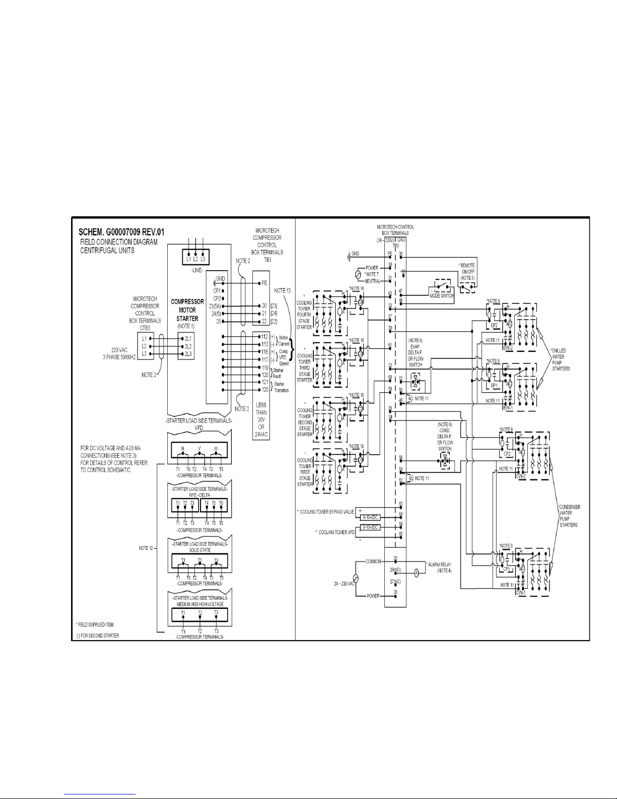
interlocks if so desired. See the Field Wiring Diagram on page 22 or on the cover of the control
panel for proper connections.
System Pumps
Operation of the chilled water pump can be:
1. Cycle the pump with the compressor,
2. Operate continuously
3. Start automatically by a remote source.
The cooling tower pump must cycle with the machine. The easiest way to accomplish this is to let the
chiller MicroTechⅢ controller control the pump. The controller is programmed to start and stop the pump
at the correct times. The holding coil of the cooling tower pump motor starter must be rated at 220 volts,
50/60 Hz, with a maximum volt-amperage rating of 100. A control relay is required if the voltageamperage rating is exceeded. See the Field Wiring Diagram on page 28 or in the cover of control panel for
proper connections.
All interlock contacts must be rated for no less than 10 inductive amps. The alarm circuit provided in
the control center utilizes 220-volts AC. The alarm used must not draw more than 10 volt amperes.
Control Panel Switches
Three On/Off switches are located in the Control Panel, which is adjacent to the operator interface panel,
and have the following function:
UNIT shuts down the chiller through the normal shutdown cycle of unloading the compressor(s) and
provides a post-lube period.
COMPRESSOR one switch for the compressor on a unit, executes an immediate shutdown without
the normal shutdown cycle.
CIRCUIT BREAKER disconnects optional external power to system pumps and tower fans.
A fourth switch located on the front of the Control box and labeled EMERGENCY STOP SWITCH stops
the compressor immediately. It is wired in series with the COMPRESSOR On/Off switch.
D-EIMWC01308-16EN - 30/40
Page 31
Surge Capacitors
All low voltage units (except those with solid state starters or VFDs) are supplied with standard surge
capacitors to protect compressor motors from electrical damage resulting from high voltage spikes.
For free-standing starters, factory or customer supplied, the capacitors are mounted in the motor terminal
box and must be connected to the motor terminals with leads less than 18 inches (460 mm) long when the
motor is being wired.
Field Wiring Diagram
Figure 8, Field Wiring Diagram
D-EIMWC01308-16EN - 31/40
Page 32

Wiring Diagram Notes
1. Compressor motor starters are either factory mounted and wired or shipped separate for field mounting and
wiring. If provided by others starters must comply with Daikin specification 359A999. All line and load side
power conductors must be copper, with ampacity based on 75°C conductor rating. (Exception: for equipment
rated over 2000 volts, 90°C or 105°C rated conductors shall be used.
2. Field control wiring between the starter and the control panel is required with free-standing starters.
Minimum wire size for 115 VAC to 220 VAC is 12 GA. for a maximum length of 50 feet. If greater than 50
feet refer to Daikin for recommended wire size minimum. Wire size for 24 VAC is 18 GA. All wiring to be
installed as NEC class 1 wiring system. All 20 VAC wiring must be run in separate conduit from 115 VAC
and 220 VAC wiring. Main power wiring between starter and motor terminal is factory installed when units
are supplied with unit mounted starters. Wiring of free standing starter must be wired in accordance with
NEC and connection to compressor motor terminals must be made with copper wire and copper lugs only.
3. For optional sensor wiring see unit control diagram. It is recommended that DC wires be run separately from
115 VAC to 220 VAC wiring.
4. A customer furnished 24 to 230 VAC power for alarm relay coil may be connected between TB3 terminals 28
power and 26 neutral of the control panel. For normally open contacts wire between 26 and 29, for normally
closed wire between 26 and 27. The alarm is operator programmable. Maximum rating of the alarm relay
coil is 25 VA .
5. Remote on/off control of unit can be accomplished by installing a set of dry contacts between terminals 36
and 25.
6. Evaporator and condenser flow switches are required. Factory mounted flow switches are standard on WCT
units. Field installed flow switches must be wired as shown. If field supplied pressure differential switches
are used then these must be installed across the vessel and not the pump. Paddle flow switches may also be
field installed if desired.
7. Customer supplied 24 to 230 VAC 20 amp power for optional evaporator and condenser water pump control
power and tower fans is supplied to unit control terminals (TB3) 30 power / 31 neutral, PE equipment
ground.
8. Optional customer supplied 24-220 VAC 25 VA maximum coil rated chilled water pump relay (EP 1 and 2)
may be wired as shown. This optional will cycle the chilled water pump in response to chiller demand.
9. The condenser water pump must cycle with the unit. A customer supplied 24-220 VAC 25 VA maximum coil
rated condenser water pump relay (CP 1 and 2) is to be wired as shown. Units with free cooling must have
condenser water above 60
10. Optional customer supplied 24-220 VAC 25 VA maximum coil rated cooling tower fan relays (C1 – C2
o
before starting.
standard, C3 – C4 optional) may be wired as shown. This option will cycle the cooling tower fans in order to
maintain unit head pressure.
11. Auxiliary 24 VAC rated contacts in both the chilled water and condenser water pump starters should be wired
as shown and remove MJ.
12. For VFD, Wye-Delta, and solid state starters connected to six (6) terminal motors. The conductors between
the starter and motor carry phase current and selection shall be based on 58 percent of the motor rated load
amperes (RLA). Wiring of free standing starter must be in accordance with the NEC and connection to the
compressor motor terminals shall be made with copper wire and copper lugs only. Main power wiring
between the starter and motor terminals is factory installed when chillers are supplied with unit-mounted
starters.
13. Motor current has three selectable options as follows : 0-5V/0-10V/0-20mA by build in HMI. Compressor
VFD speed has two selectable options as follows : 0-10V/4-20m.
D-EIMWC01308-16EN - 32/40
Page 33

Prestart System Checklist
Yes No N/A
Unit
Visible damages to unit……………………………………………………………………
Unit structural support adequate and level per IM……………..…………………………
Vibration pads installed per IM………………………………………………………..….
Adequate clearances for service and code requirements……………………………….. …
Chilled Water
Piping complete, vent drain, & gauge connections installed………………………………
Piping properly supported and stress free………………………………………………..
Water system flushed, filled, vented, glycol and water treatment applied necessary ........
Pumps installed, (rotation checked), strainers cleaned ......................................................
Controls (3-way, face and bypass dampers, bypass valves, etc.) operable ........................
Water system operated and flow balanced to meet unit design requirements ...................
Condenser Water
Piping complete, vent drain, & gauge connections installed,
Piping properly supported and stress free ..........................................................................
Cooling tower flushed, filled and vented, water treatment complete ................................
Condenser water piping flushed, filled and vented ...........................................................
Pumps installed, (rotation checked), strainers cleaned .....................................................
Controls (3-way, bypass valves, etc.) operable ................................................................
Water system operated and flow balanced to meet unit requirements ..............................
Electrical
All copper conductors connected to unit ……………………………………….………..
220-volt service completed, but not connected to control panel ......................................
Power leads connected to starter; load leads run to compressor ready for
connection when service engineer is on hand for start-up ................................................
(Do not connect starter or compressor terminals)
All interlock wiring complete between control panel and complies with specifications ..
Starter complies with specifications .................................................................................
Pump starters and interlock wired ....................................................................................
Cooling tower fans and controls wired .............................................................................
Wiring complies with National Electrical Code and local codes ......................................
Condenser pump starting relay (CWR) installed and wired .............................................
Miscellaneous
Relief valve piping complete ............................................................................................
Thermometer wells, thermometers, gauges, control wells, controls, etc., installed ..........
BAS control sequences, functions and settings confirmed……………………….............. .
Minimum system load of 80% of machine capacity available for testing
and adjusting controls .......................................................................................................
Note: The checklist must be completed and sent to the local Daikin service location two weeks prior to
start.
D-EIMWC01308-16EN - 33/40
Page 34

Important information regarding the refrigerant used
This product contains fluorinated greenhouse gase. Do not vent gases into the atmosphere.
Refrigerant type: R134a
(1)
GWP
(1)
The refrigerant quantity is indicated on the unit name plate.
Periodical inspections for refrigerant leaks may be required depending on European or local legislation. Please
contact your local dealer for
more information.
value: 1430
GWP = global warming potential
D-EIMWC01308-16EN - 34/40
Page 35
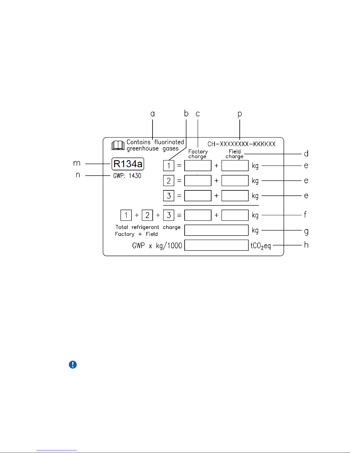
Factory and Field charged units instructions
(Important information regarding the refrigerant used)
The refrigerant system will be charged with fluorinated greenhouse gases.
Do not vent gases into the atmosphere.
1 Fill in with indelible ink the refrigerant charge label supplied with the product as following instructions:
- the refrigerant charge for each circuit (1; 2; 3)
- the total refrigerant charge (1 + 2 + 3)
- calculate the greenhouse gas emission with the following formula:
GWP value of the refrigerant x Total refrigerant charge (in kg) / 1000
a Contains fluorinated greenhouse gases
b Circuit number
c Factory charge
d Field charge
e Refrigerant charge for each circuit (according to the number of circuits)
f Total refrigerant charge
g Total refrigerant charge (Factory + Field)
h Greenhouse gas emission of the total refrigerant charge expressed
as tonnes of CO2 equivalent
m Refrigerant type
n GWP = Global Warming Potential
p Unit serial number
2 The filled out label must be adhered inside the electrical panel.
Periodical inspections for refrigerant leaks may be required depending on European or local legislation.
Please contact your local dealer for more information.
NOTICE
In Europe, the greenhouse gas emission of the total refrigerant charge in the system
(expressed as tonnes CO2 equivalent) is used to determine the maintenance intervals.
Follow the applicable legislation.
D-EIMWC01308-16EN - 35/40
Page 36
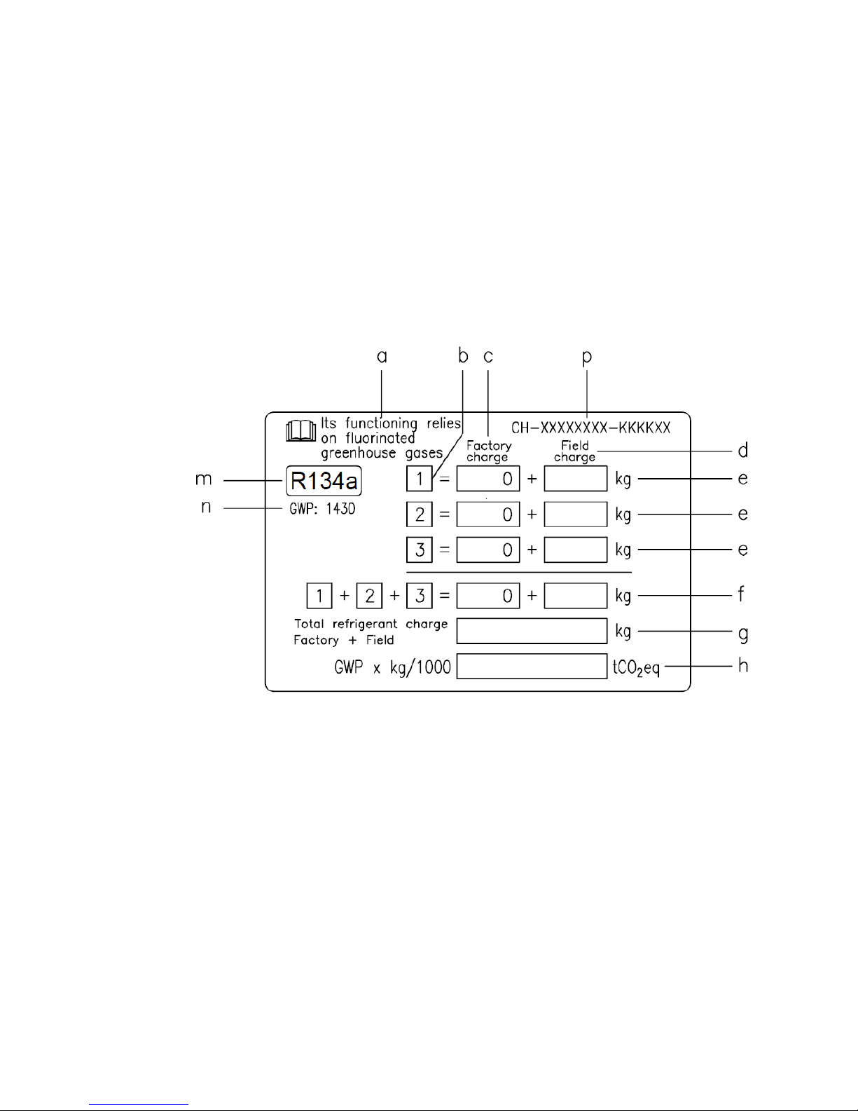
Formula to calculate the greenhouse gas emission:
GWP value of the refrigerant x Total refrigerant charge (in kg) / 1000
Use the GWP value mentioned on the greenhouse gases label. This GWP value isbased on the 4th IPCC
Assessment Report. The GWP value mentioned in the manual might be outdated (i.e. based on the 3rd
IPCC Assessment Report)
Field charged units instructions
(Important information regarding the refrigerant used)
The refrigerant system will be charged with fluorinated greenhouse gases.
Do not vent gases into the atmosphere.
1 Fill in with indelible ink the refrigerant charge label supplied with the product as following instructions:
- the refrigerant charge for each circuit (1; 2; 3)
- the total refrigerant charge (1 + 2 + 3)
- calculate the greenhouse gas emission with the following formula:
GWP value of the refrigerant x Total refrigerant charge (in kg) / 1000
a Its functioning relies on fluorinated greenhouse gas
b Circuit number
c Factory charge
d Field charge
e Refrigerant charge for each circuit (according to the number of circuits)
f Total refrigerant charge
g Total refrigerant charge (Factory + Field)
h Greenhouse gas emission of the total refrigerant charge expressed
as tonnes of CO2 equivalent
m Refrigerant type
n GWP = Global Warming Potential
p Unit serial number
2 The filled out label must be adhered inside the electrical panel.
Periodical inspections for refrigerant leaks may be required depending on European or local legislation.
Please contact your local dealer for more information.
D-EIMWC01308-16EN - 36/40
Page 37

NOTICE
In Europe, the greenhouse gas emission of the total refrigerant charge in the system
(expressed as tonnes CO2 equivalent) is used to determine the maintenance intervals.
Follow the applicable legislation.
Formula to calculate the greenhouse gas emission:
GWP value of the refrigerant x Total refrigerant charge (in kg) / 1000
Use the GWP value mentioned on the greenhouse gases label. This GWP value is
based on the 4th IPCC Assessment Report. The GWP value mentioned in the manual might be outdated (i.e.
based on the 3rd IPCC Assessment Report)
D-EIMWC01308-16EN - 37/40
Page 38
Disposal
The unit is made of metal and plastic parts. All these parts must be disposed of in accordance with the local
regulations in terms of disposal.
Lead batteries must be collected and taken to specific refuse collection centres.
D-EIMWC01308-16EN - 38/40
Page 39

D-EIMWC01308-16EN - 39/40
Page 40

The present publication is drawn up by of information only and does not constitute an offer binding upon Daikin Applied
Europe S.p.A.. Daikin Applied Europe S.p.A. has compiled the content of this publication to the best of its knowledge. No
express or implied warranty is given for the completeness, accuracy, reliability or fitness for particular purpose of its
content, and the products and services presented therein. Specification are subject to change without prior notice. Refer to
the data communicated at the time of the order. Daikin Applied Europe S.p.A. explicitly rejects any liability for any direct or
indirect damage, in the broadest sense, arising from or related to the use and/or interpretation of this publication. All
content is copyrighted by Daikin Applied Europe S.p.A..
DAIKIN APPLIED EUROPE S.p.A.
Via Piani di Santa Maria, 72 - 00072 Ariccia (Roma) - Italia
Tel: (+39) 06 93 73 11 - Fax: (+39) 06 93 74 014
http://www.daikinapplied.eu
D-EIMWC01308-16EN - 40/40
 Loading...