

DAIKIN VRV-WII INSTALLATION MANUAL

EDUS 30 - 607 - N
AMERICAS
Installation
AMERICAS
AMERICAS

EDUS30-607-N
Installation of
Outdoor Units
1. Center of Gravity................................................................ 2
2. Installation and Repair Space Drawing.............................. 3
3. REFNET Pipe System ...................................................... 4
3.1 Layout Example .......................................................... 4
3.2 Max. Refrigerant Piping Length .................................. 5
3.3 Field Refrigerant Piping .............................................. 6
3.4 REFNET Joints and Headers ..................................... 7
4. REFNET Pipe System ...................................................... 9
4.1 REFNET Joint (Branch Kit).......................................... 9
4.2 REFNET Header (Branch Kit) ..................................... 17
4.3 Outdoor Unit Multi Connection Piping Kit ................... 25
5. Installation.......................................................................... 27
5.1 RWEYQ60, 72, 84, 144, 168, 216, 252MTJU.............. 27
Installation of Outdoor Units 1

Center of Gravity EDUS30-607-N
1. Center of Gravity
RWEYQ60, 72, 80MTJU
4D055409
2 Installation of Outdoor Units
EDUS30-607-N Installation and Repair Space Drawing
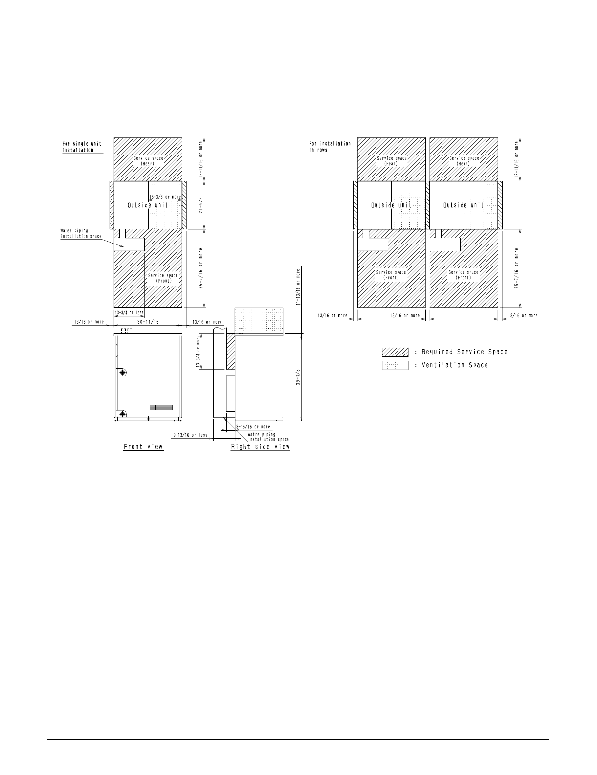
2. Installation and Repair Space Drawing
RWEYQ60, 72, 84MTJU
3D055408
Installation of Outdoor Units 3
REFNET Pipe System EDUS30-607-N
3. REFNET Pipe System
3.1 Layout Example
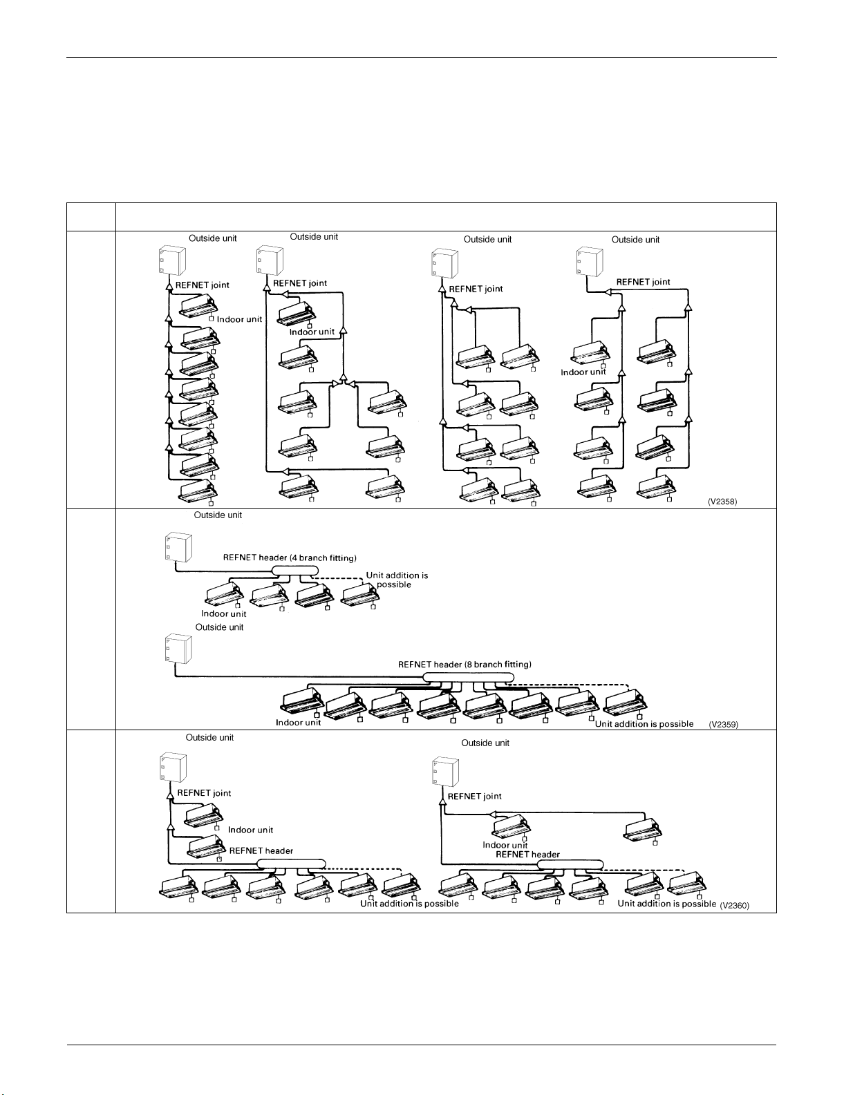
3.1.1 Heat Pump System
Use of the particular branch fitting appropriate to each individual unit type not only permits the pipes to be laid
with ease but also increases the reliability of the system as a whole.
Type of
fitting
Line branch fitting
Sample systems
(Pipes containing REFNET joints only)
Header branch fitting
(Piping consists of REFNET headers only)
Mixed branch fittings
(Piping including both headers and joints)
Units can be added by connecting them directly to the REFNET header or REFNET joint. Further branches cannot be
included in the system below the REFNET header branch.
Notes
1. When the capacity ratio of the indoor system to the outside unit is more than 100% and when all the indoor units are
in operation at the same time then the rated capacity of each unit will be somewhat reduced.
2. Special purpose REFNET pipe components must be used for all the pipe work. For further details concerning choice
of components, types of components, etc.
4 Installation of Outdoor Units
EDUS30-607-N REFNET Pipe System
3.2 Max. Refrigerant Piping Length
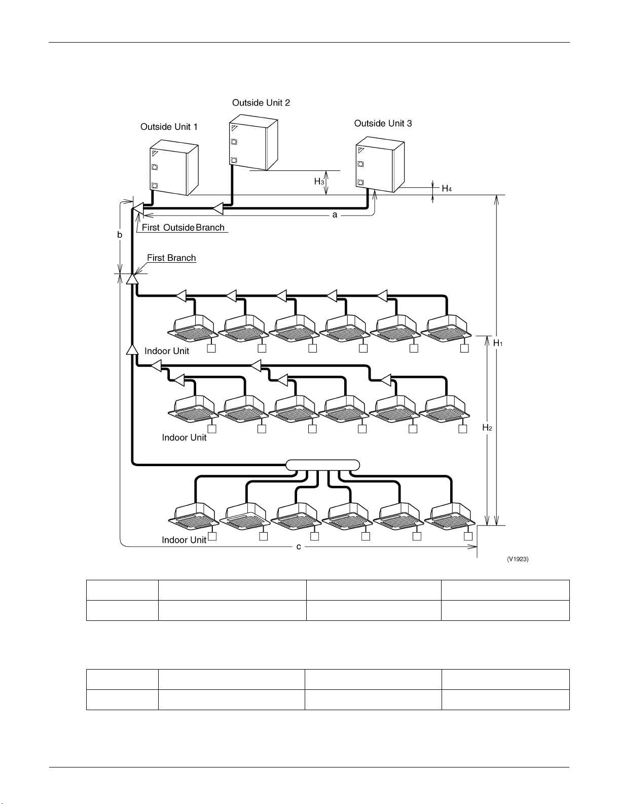
3.2.1 Heat Pump System
Max. Refrigerant Piping Length (Actual Piping Length)
Max. Refrigerant
Piping Length (ft)
First outside Branch ~ Outside units
32.81ft or less than 32.81ft 131.2ft or less than 131.2ft 393.7ft or less than 393.7ft
[a]
First Branch ~ Indoor Units
[c]
Outside Units ~ Indoor Units
[b+c]
Total Extension length
Total Piping length from outside unit to all indoor units ≤300m
Max. Level Difference
Max. Level
Difference (ft)
Outside Units ~ Indoor Units
164.0ft or less than 164.0ft
[H
1
Note 3
]
Between the Indoor Units
[H2]
49.21ft or less than 49.21ft 6.562ft or less than 6.562ft
Between the Outside Units
[H3 , H4]
Notes:
1. Be sure to use a REFNET Piping Kit for the branch of piping.
2. A Branch Part can not be installed to the down flow of the REFNET Header.
3. If the outside unit is located under the indoor unit, the level difference is a maximum of 131.2ft.
Installation of Outdoor Units 5

REFNET Pipe System EDUS30-607-N
3.3 Field Refrigerant Piping
3.3.1 Heat Pump Series
1. The following materials should be used for all refrigerant piping.
Materials: Deoxidized phosphorous seamless copper pipe (for external diameters of 1/2” or more, C1220T-0 for the
rest) or equivalent
2. The tips for insulation
Gas piping must be insulated.
Be sure to insulate the liquid-side and gas-side piping for the inter-unit piping and the refrigerant branch kits and
always use 18-type or better insulation for the oil pressure equalizer.
Materials: Glass fiber or heat resistant polyethylene foam.
Thickness: 10mm or more
Heat resistance: Gas pipe : 248°F or more / Liquid pipe : 158°F or more
If you think the humidity around the cooling piping might exceed 86°F and RH65%, reinforce the insulation on the
cooling piping (at least 0.065ft thick). Condensation might form on the surface of the insulation.
Insulation of both liquid and gas pipe
6 Installation of Outdoor Units
EDUS30-607-N REFNET Pipe System
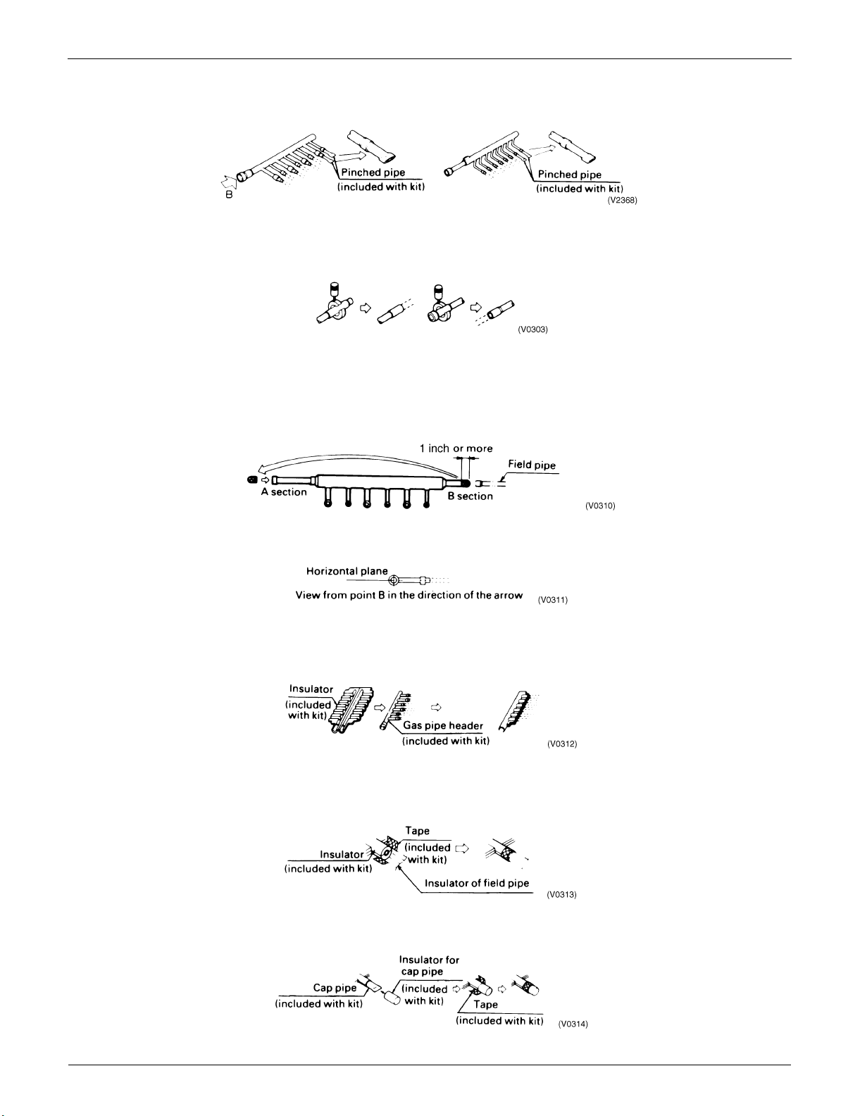
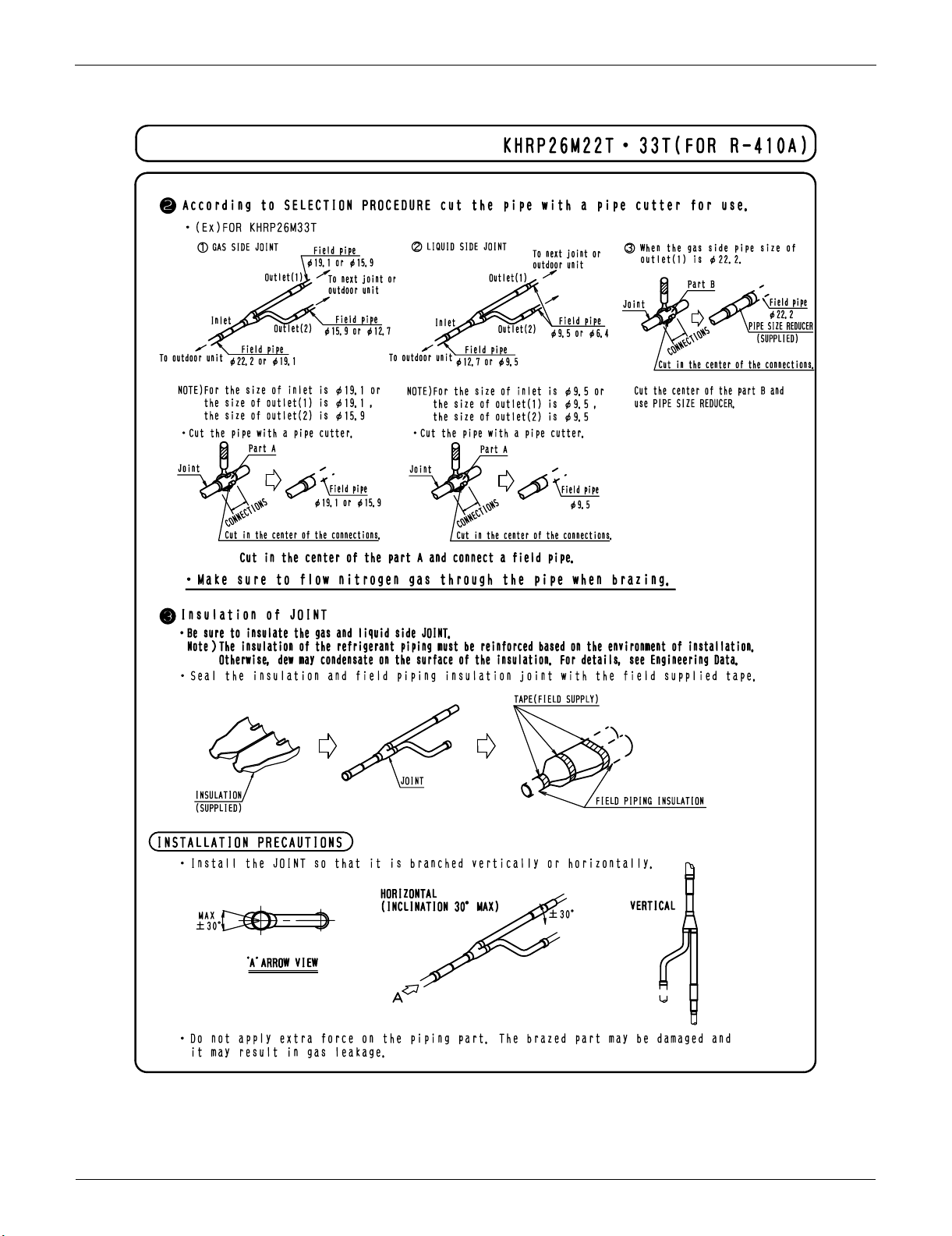
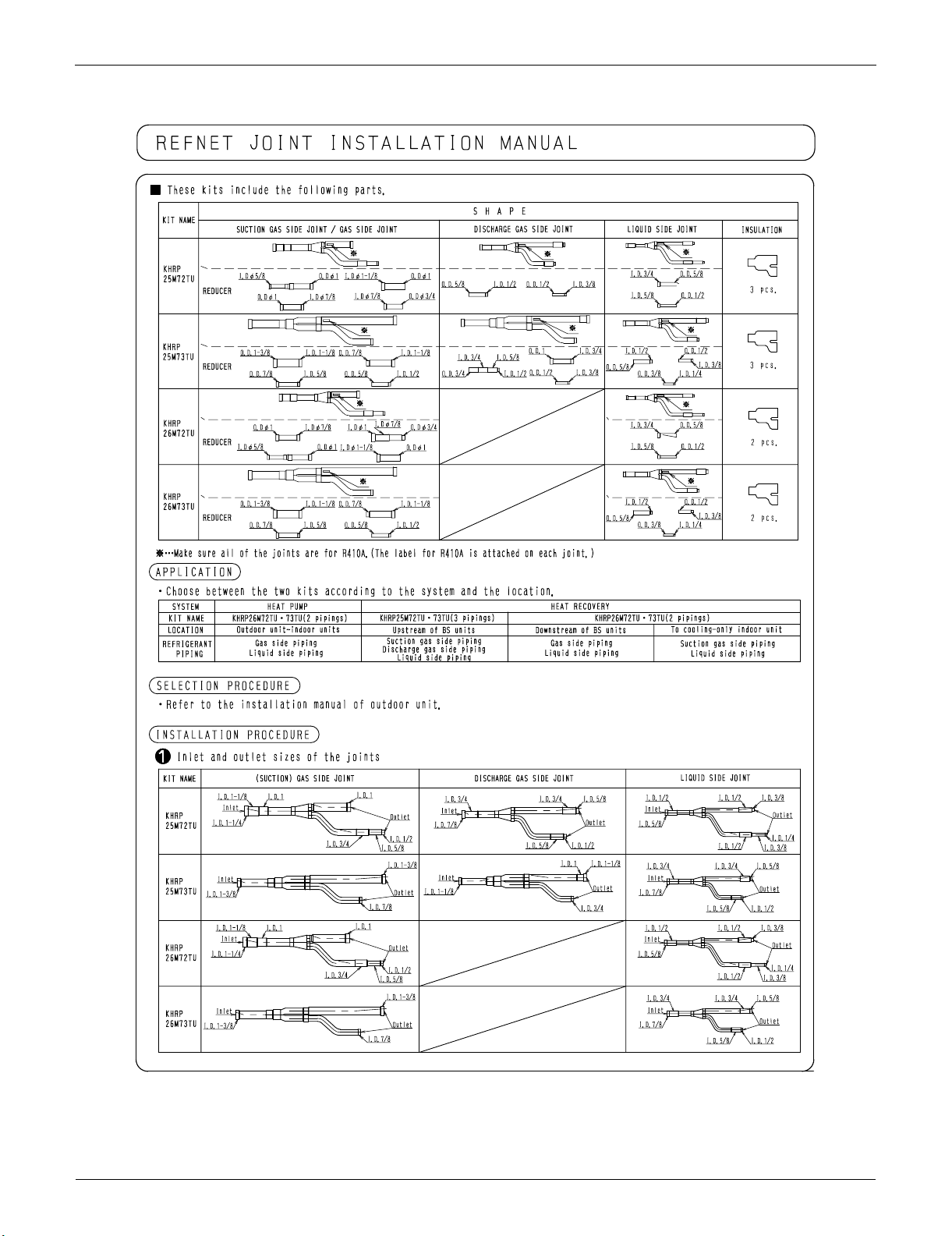
3.4 REFNET Joints and Headers
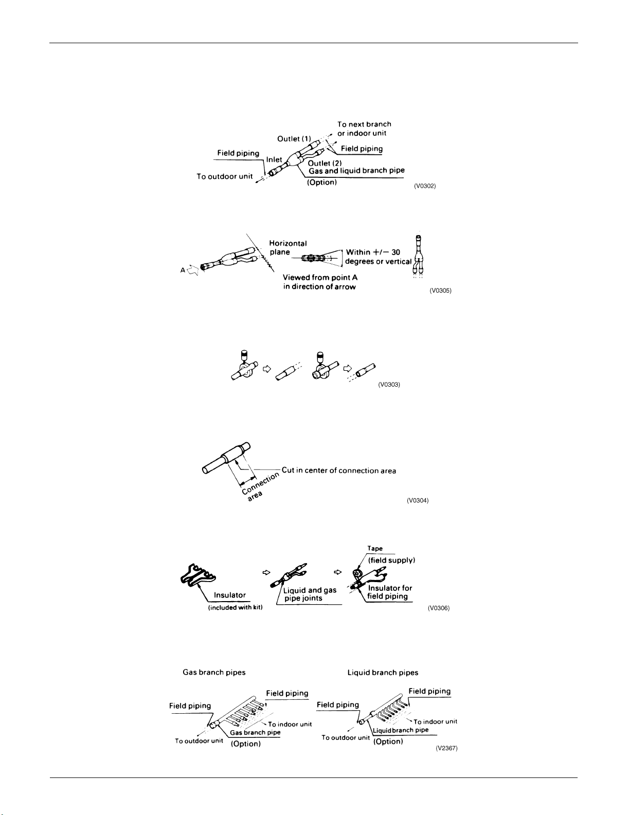
3.4.1 REFNET Joints
For gas and liquid branch pipes
Make sure that all branch pipes are fitted such that they branch either horizontally or vertically.
When the size of the selected field piping is different from that of branch pipe then the connecting section should be
cut with a pipe cutter as shown in the figure below.
When you are cutting an inlet or outlet pipe with a pipe cutter make sure that you make the cut in the center of the
connection area.
Branch pipes must be insulated in accordance with the handbook which comes with each kit.
3.4.2 REFNET Header
Installation of Outdoor Units 7
REFNET Pipe System EDUS30-607-N
When the number of indoor units to be connected to the branch pipes is less than the number of branch pipes
available for connection then cap pipes should be fitted to the surplus branches.
When the size of the selected field piping is different from that of branch pipe then the connecting section should be
cut with a pipe cutter as shown in the figure below.
When field piping is connected to the B section of the inlet/outlet pipe on the outdoor unit side of the liquid pipe
header.
Cut the B section with a pipe cutter as shown below and connect it to the A section.
Connect the flared section of the field pipe to the B section.
Fit the branch pipe so that the branch lies in a horizontal plane.
The branch pipe must be insulated in accordance with the instruction manual which comes with each kit.
1. Use the insulator included in the kit to insulate the header.
2. Joints between insulators included in the kit and those already applied to the field piping should be sealed with the
tape which is also included in each kit.
3. Any cap pipes should also be insulated using the insulator provided with each kit and then taped as described above.
8 Installation of Outdoor Units
EDUS30-607-N REFNET Pipe System
A
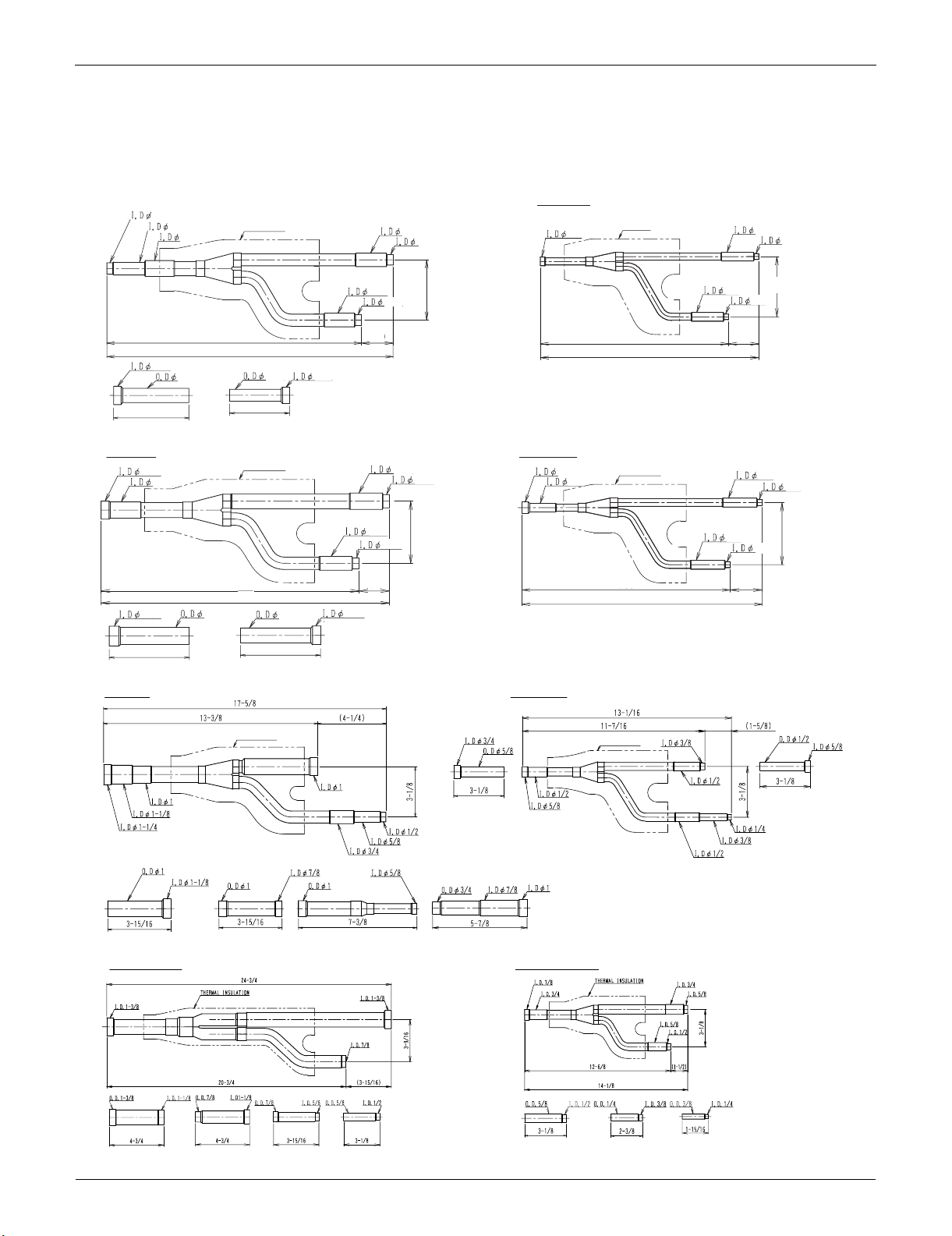
4. REFNET Pipe System
4.1 REFNET Joint (Branch Kit)
KHRP26M22T
Gas Side
1/2
5/8
3/4
Insulation
5/8
1/2
Liquid Side
3/8
Insulation
3/8
(unit:in)
1/4
7/8
4
KHRP26M33T
Gas Side
7/8
3/4
1
4
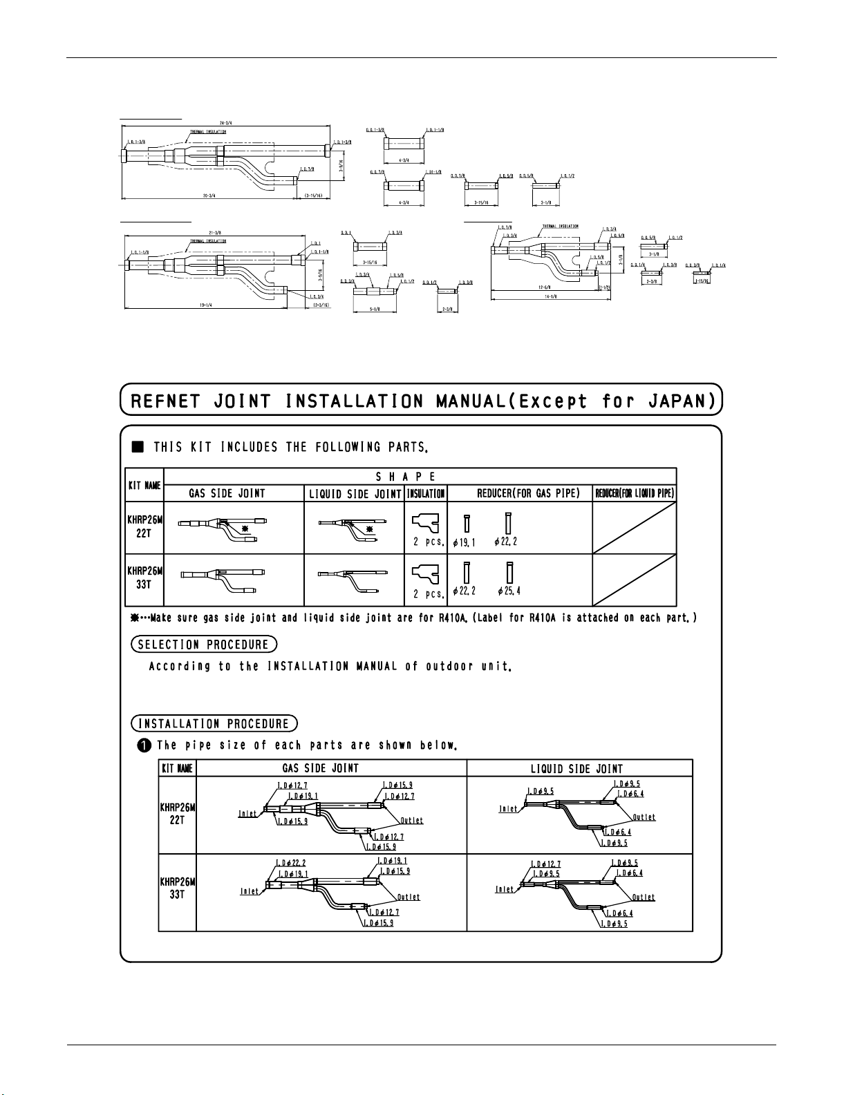
KHRP26M72TU
Gas Side
3/4
12-11/16
7/8
13-1/3
15
Insulation
5/8
3
Insulation
14-1/4
3
5/8
1/2
1-1/2
3/4
9-7/8
11-1/2
3/8
1-1/2
3
1/4
D3K03622C
Liquid Side
3/4
5/8
3
5/8
1/2
1-1/2
3/4
4
7/8
1/2
3/8
Liquid Side
Insulation
10-1/4
Insulation
11-13/16
3/8
3/8
1/4
3
1/4
1-1/2
D3K03623
D3K04887A
KHRP26M73TU
Gas Side Joint
Liquid Side Joint
D3K05572
Installation of Outdoor Units 9
REFNET Pipe System EDUS30-607-N
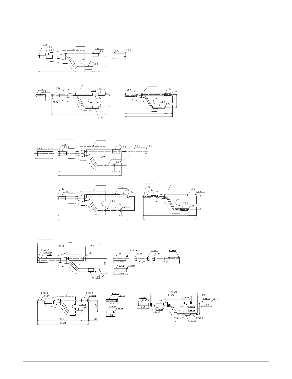
KHRP25M22T
Suction gas side
1/2
5/8
3/4
12
13-1/3
Insulation
5/8
1-1/2
5/8
1/2
3
1/2
3/4
5/8
3
Discharge gas side
3/8
1/2
2-1/3
KHRP25M33T
1
7/8
1
4
Discharge gas side
5/8
1/2
12
13-1/3
Suction gas side
7/8
3/4
5/8
3/4
12-3/4
14-1/2
Insulation
14-1/5
16
1/2
5/8
3/8
1-1/2
Insulation
Insulation
3/8
3
1/2
5/8
1-1/2
5/8
3/4
1/2
1/2
1-1/2
3/4
1/2
Liquid side
5/8
3/8
3/8
5/8
1/4
Insulation
9-7/8
11-1/2
7/8
3/4
4
Liquid side
1/2
1/2
3
3/8
10-1/4
3/8
11-13/16
1-1/2
3/8
1/4
Insulation
1/4
3
D3K03626B
3/8
1/4
3
3/8
1/4
1-1/2
D3K03627B
KHRP25M72TU
Suction gas side
Insulation
Liquid sideDischarge gas side
Insulation
Insulation
D3K04888A
10 Installation of Outdoor Units
EDUS30-607-N REFNET Pipe System
KHRP25M73TU
Suction gas side Joint
Liquid side JointDischarge gas side Joint
D3K05573
KHRP26M22T, KHRP26M33T
C : 3P113149B
Installation of Outdoor Units 11
REFNET Pipe System EDUS30-607-N
C : 3P113149B
12 Installation of Outdoor Units

EDUS30-607-N REFNET Pipe System
KHRP25M22T, KHRP25M33T
C : 3P113621B
Installation of Outdoor Units 13

REFNET Pipe System EDUS30-607-N
C : 3P113621B
14 Installation of Outdoor Units
EDUS30-607-N REFNET Pipe System
KHRP25M72TU, KHRP26M72TU, KHRP25M73TU, KHRP26M73TU
3P161697D
Installation of Outdoor Units 15
 Loading...