

Daikin RXYQ5M, RXYQ12M, RXYQ16M, RXYQ8M, RXYQ10M Introduction Manual
...
technical data
Systems
Introduction
• Introduction
IIntroduction
Table of contents
1 Possible indoor units using R-410A..........................................................................2
2 Possible outdoor units using R-410A......................................................................3
Indoor unit capacity index.............................................................................................................................3
3 Nomenclature
Indoor units.............................................................................................................................................................4
Outdoor units ........................................................................................................................................................5
4 line-up..........................................................................................................6
5 technology ...............................................................................................7
6Main features
Creating maximum comfort......................................................................................................................10
Energy efficient solution..............................................................................................................................13
High reliability .....................................................................................................................................................16
Eco friendly...........................................................................................................................................................18
Easy and flexible design................................................................................................................................19
Simple and rapid installation.....................................................................................................................22
7Selection procedure
Selection procedure System based on cooling load..................................................................26
Capacity correction ratio .............................................................................................................................29
Refnet pipe system..........................................................................................................................................37
Refnet pipe selection .....................................................................................................................................39
• Systems • Introduction
1
• Introduction
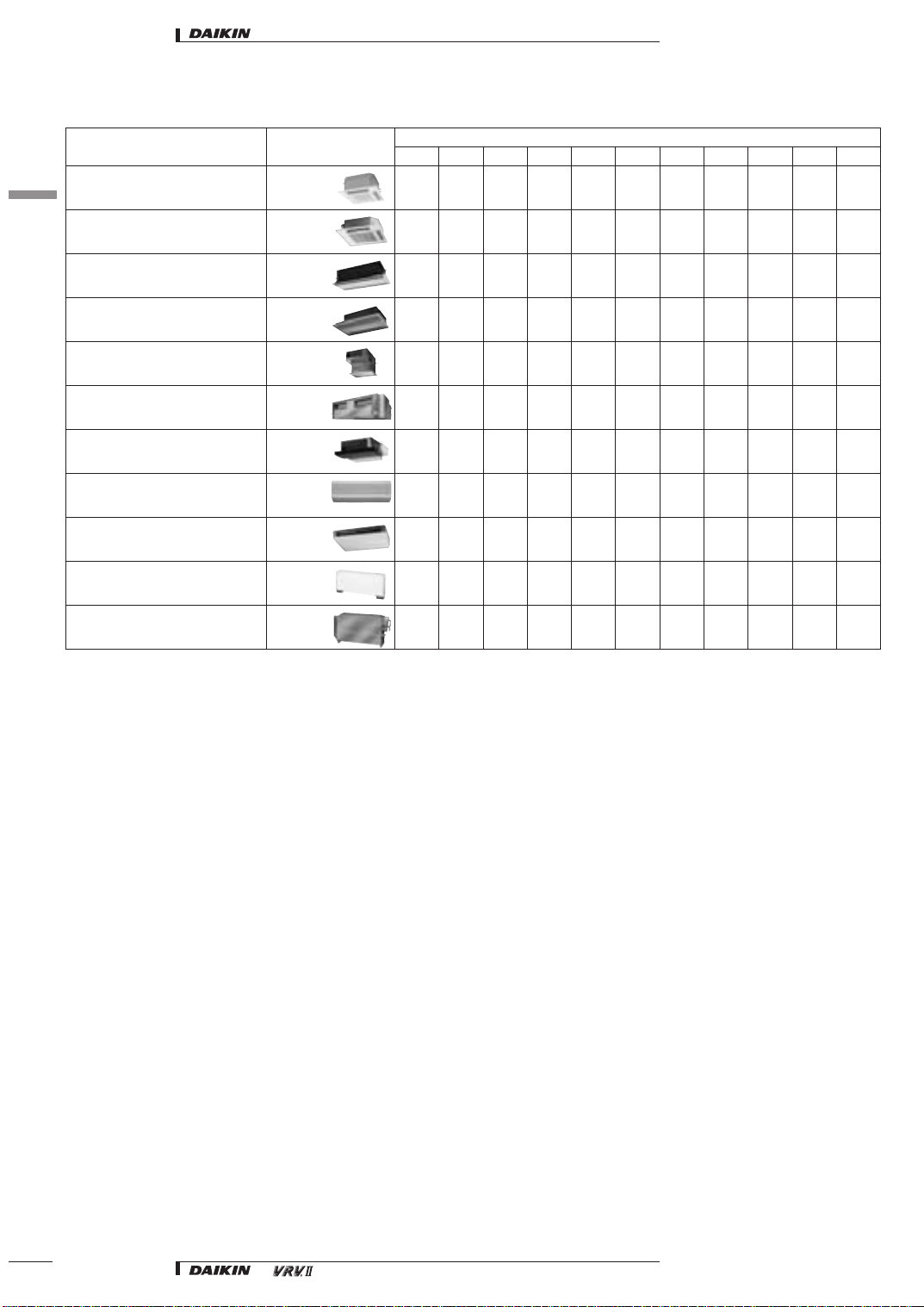
1 Possible indoor units using R-410A
Description Indoor unit
1
1
4-way blow ceiling mounted cassette (600 mm x 600 mm) FXZQ-MVE xxxxx
4-way blow ceiling mounted cassette FXFQ-M7V1B xxxxxxxxx
2-way blow ceiling mounted cassette FXCQ-M7V1B xxxxxxx x
Ceiling mounted corner cassette FXKQ-MVE x x x x
Concealed ceiling unit FXSQ-M7V1B xxxxxxxxx
Concealed ceiling unit (large) FXMQ-MVE xxxxxxxx
Concealed ceiling unit (small) FXDQ-M7V1B x x
Wall mounted unit FXAQ-MVE xxxxxx
Ceiling suspended unit FXHQ-MVE x x x
Floor standing unit FXLQ-MVE xxxxxx
Concealed floor standing unit FXNQ-MVE xxxxxx
20 25 32 40 50 63 80 100 125 200 250
Size
2
• Systems • Introduction
• Introduction
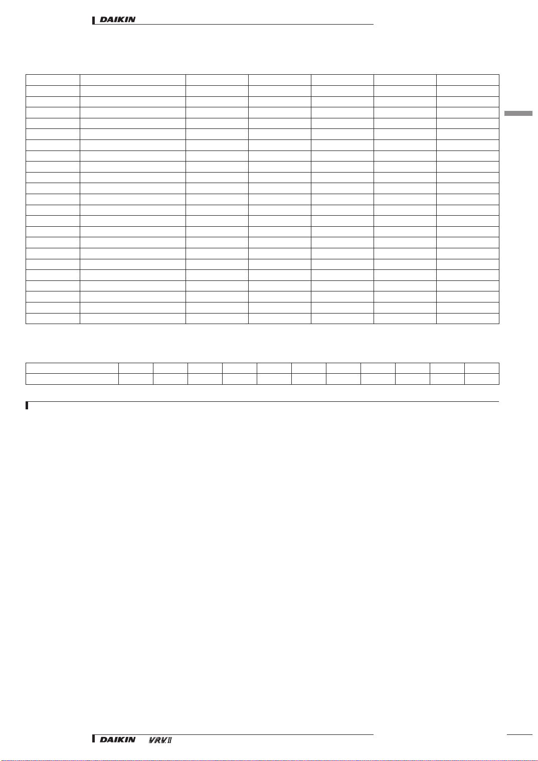
2 Possible outdoor units using R-410A
VRV II heat pump Fixed combinations Nr. of outdoors Nr. of compressors Nr. of connectable indoor units Minimum capacity index Maximum capacity index
RXYQ5M RXYQ5M 1 1 8 63 163
RXYQ8M RXYQ8M 1 2 13 100 260
RXYQ10M RXYQ10M 1 2 16 125 325
RXYQ12M RXYQ12M 1 2 20 150 390
RXYQ14M RXYQ14M 1 3 20 175 455
RXYQ16M RXYQ16M 1 3 20 200 520
RXYQ18M RXYQ8M + RXYQ10M 2 4 20 225 585
RXYQ20M RXYQ10M x 2 2 4 20 250 650
RXYQ22M RXYQ10M + RXYQ12M 2 4 22 275 715
RXYQ24M RXYQ10M + RXYQ14M 2 5 32 300 780
RXYQ26M RXYQ10M + RXYQ16M 2 5 32 325 845
RXYQ28M RXYQ12M + RXYQ16M 2 5 32 350 910
RXYQ30M RXYQ14M + RXYQ16M 2 6 32 375 975
RXYQ32M RXYQ16M x 2 2 6 32 400 1,040
RXYQ34M RXYQ10M x 2 + RXYQ14M 3 7 34 425 1,105
RXYQ36M RXYQ10M x 2 + RXYQ16M 3 7 36 450 1,170
RXYQ38M RXYQ10M + RXYQ12M + RXYQ16M 3 7 38 475 1,235
RXYQ40M RXYQ10M + RXYQ14M + RXYQ16M 3 8 40 500 1,300
RXYQ42M RXYQ10M + RXYQ16M x 2 3 8 40 525 1,365
RXYQ44M RXYQ12M + RXYQ16M x 2 3 8 40 550 1,430
RXYQ46M RXYQ14M + RXYQ16M x 2 3 9 40 575 1,495
RXYQ48M RXYQ16M x 3 3 9 40 600 1,560
2-1 Indoor unit capacity index
Model 20 25 32 40 50 63 80 100 125 200 250
Capacity index 20 25 31.25 40 50 62.5 80 100 125 200 250
1
2
NOTE
1e.g. Selected indoor units: FXCQ25 + FXFQ100 + FXMQ200 + FXSQ40
Connection ratio: 25 + 100 + 200 + 40 = 365
→
Possible outdoor unit: RXYQ12M
• Systems • Introduction
3
3 Nomenclature
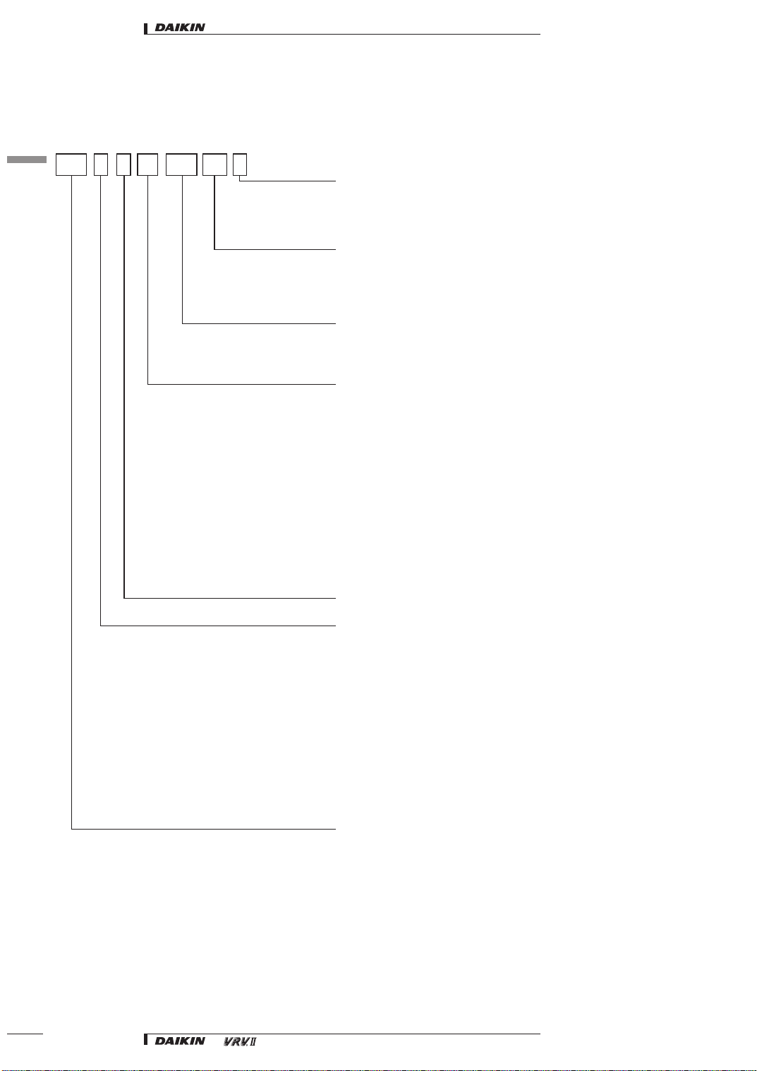
3-1 Indoor units
1
3
• Introduction
V1M40S Q BFX
Special series for Europe (CE approved)*
Power supply symbol
V1: 1~, 230V, 50Hz
VE: 1~, 220-240V, 50Hz
M: Indicates major design category
M7: Indicates DENV production
Capacity Indication
Conversion to horsepower:
20: 0.8HP
25: 1HP
32: 1.25HP
40: 1.6HP
50: 2.0HP
63: 2.5HP
80: 3.2HP
100: 4HP
125: 5HP
200: 8HP
250: 10HP
* B is not mandatory for indoor units
Indicates use with ozone friendly refrigerant R-410A
Model name
Z: 4-way blow ceiling mounted cassette (600x600mm)
F: 4-way blow ceiling mounted cassette
C: 2-way blow ceiling mounted cassette
K: Ceiling mounted corner cassette
S: Concealed ceiling unit
D: Concealed ceiling unit (small)
M: Concealed ceiling unit (large)
H: Ceiling suspended unit
A: Wall mounted unit
L: Floor standing unit
LM: Concealed floor standing unit
Indicates that this is an INVERTER HEAT PUMP/COOLING ONLY
or a HEAT RECOVERY indoor unit
4
• Systems • Introduction
• Introduction
3 Nomenclature
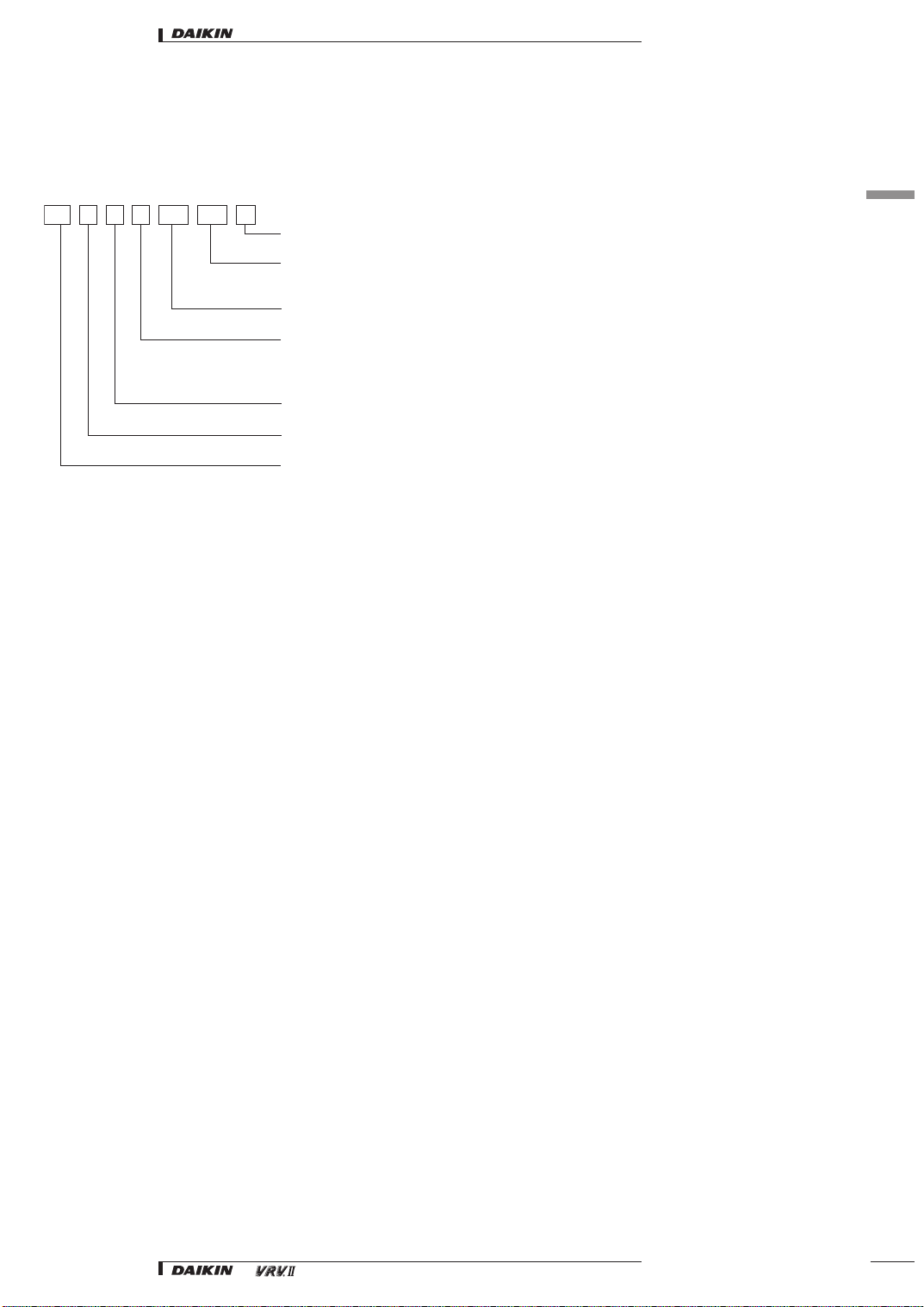
3-2 Outdoor units
• VRVII heat pump
RX Y Q 8 M7 W1 B
1
3
Special series for Europe (CE approved)
Power supply symbol:
W1: 3N~, 400V, 50Hz
M7, M: indicates major design category (internal company symbol)
5: 5HP 12:12HP
8: 8HP 14:14HP
10: 10HP 16:16HP
Indicates the use of ozone friendly refrigerant R-410A
Indicates heat pump (year around)
RX: indicates that this is an INVERTER outdoor unit
• Systems • Introduction
5
4 line-up
1
4
• Introduction
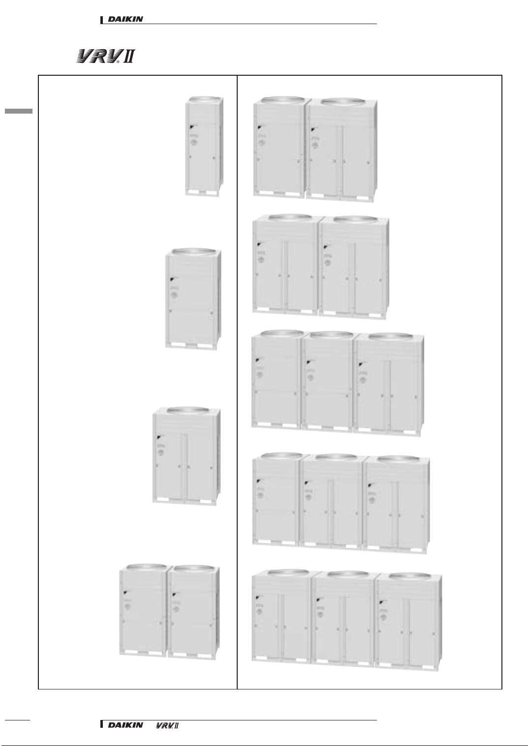
8-10HP
5HP
22-24-26HP
28-30-32HP
34-36HP
12- 14- 16 HP
38-40-42HP
18- 20HP
44-46-48HP
6
• Systems • Introduction
• Introduction
5 technology
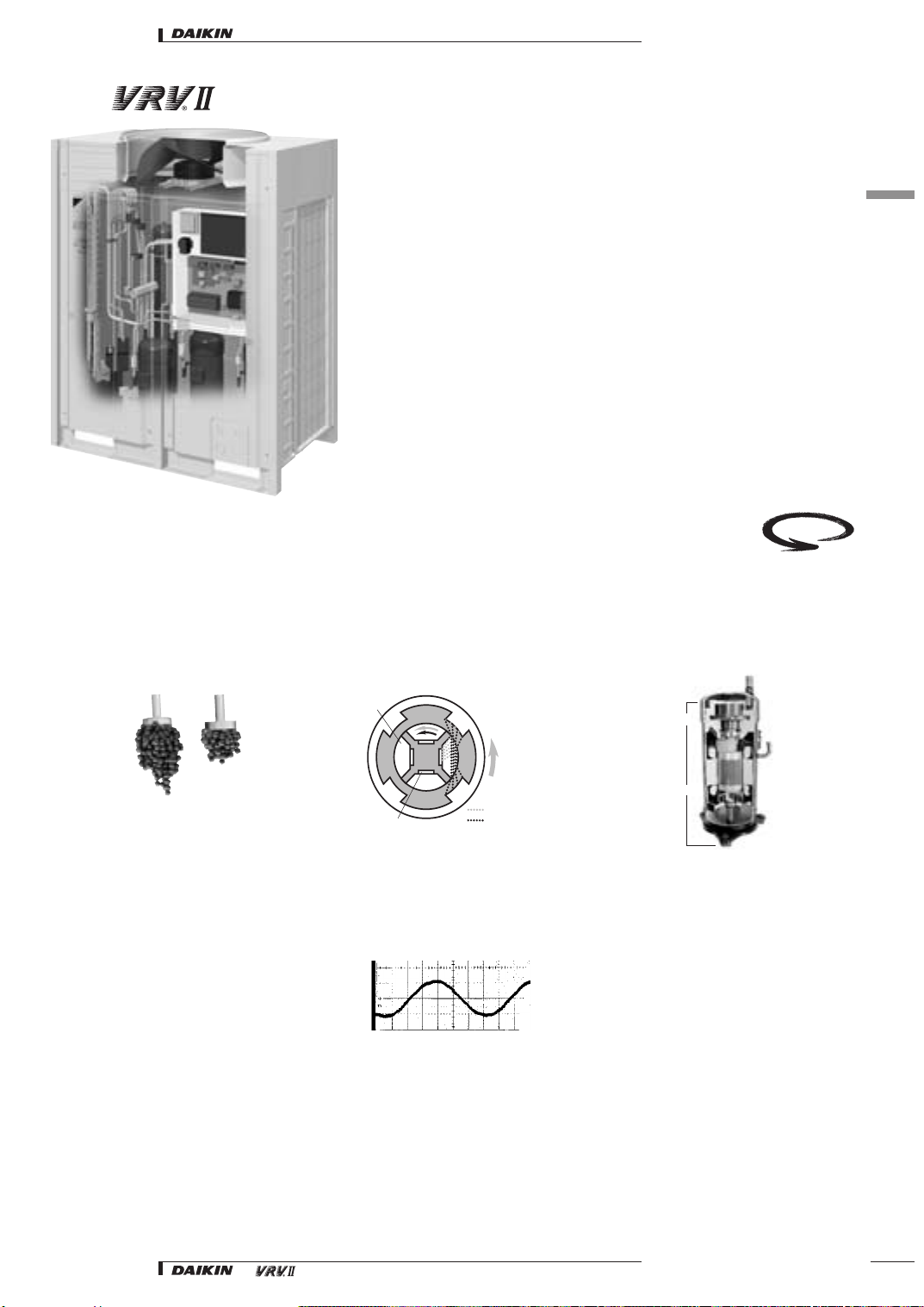
Reluctance brushless DC Compressor
The reluctance brushless DC motor provides significant increases in efficiency compared to conventional AC inverter motors, simultaneously using
2 different forms of torque (normal and reluctance torque) to produce extra power from small electric currents.
The motor comprises powerful neodymium magnets, that create the reluctance torque. These magnets ar approximately 12 times stronger than ferrite
magnets and make a major contribution to its energy saving characteristics.
Secret to raising energy-efficiency! Powerful neodymium magnets
First in the
industry
1
5
Neodymium magnet is
12 times more powerful
than the widely used
ferrite magnets
Ferrite magnet
Neodymium magnet
Sine Wave DC inverter
Optimizing the sine wave curve, results in smoother motor rotation and improved motor efficiency.
Iron
Neodymium magnet
N
N
S
S
NNNS
S
Rotating
Stator
Field
S
"Normal" torque
Reluctance torque
Low pressure side
High pressure side
Suction
Scroll
Reluctance
DC Motor
Discharge
• Systems • Introduction
7
• Introduction
5 technology
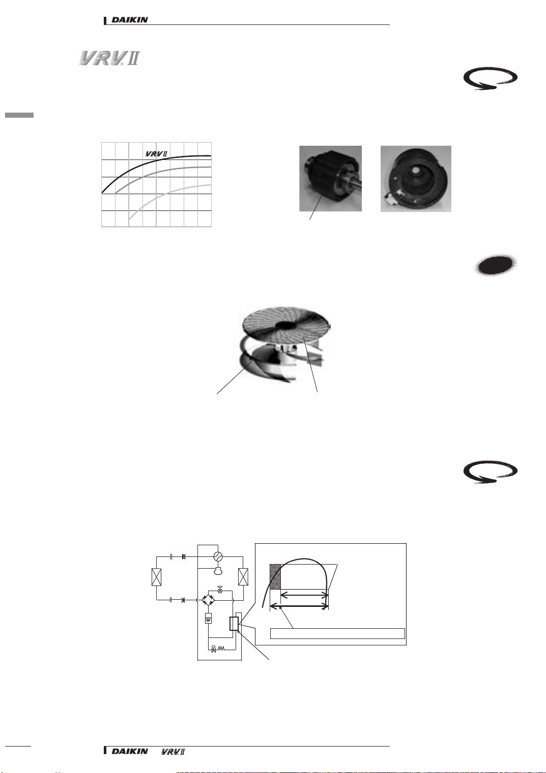
DC fan motor
1
The use of a DC fan motor offers substantial improvements in operating efficiency compared to conventional AC motors, especially during low speed
5
rotation.
First in the
industry
DC motor efficiency
(comparison with a conventional AC motor)
100
80
60
Efficiency (%)
40
20
0
20 0 300 400 500 600 700 800 900 1000
Aero fitting grill & aero spiral fan
DC motor
AC motor
Motor speed (rpm)
DC fan motor structure
magnet
N
These new features achieve a low noise fan with a large airflow, and realize a compact casing together with the compressor linking technology.
Aero spiral fan
Bending the fan blade
edge reduces turbulence,
resulting in less pressure
loss.
Aero fitting grille
New shape promotes a
spiral discharge airflow,
resulting in reduced
pressure loss.
W
E
e-Bridge circuit
Prevents accumulation of liquid refrigerant in the condenser. This results in more efficient use of the condenser surface under any circumstance and
leads in turn to better energy efficiency.
An increase in evaporative capacity systems from the newly developed refrigeration circuit, known as the SCe-bridge circuit, which adds super cooling
prior to the expansion cycle. By adopting this circuit, the COPs in both cooling and heating have been drastically improved.
Evaporative capacity can be
raised by taking super cooling
Current
Evaporative-capacity
Evaporative-capacity has been improved by adopting the SCe-Bridge Circuit.
SCe-Bridge Circuit
8
• Systems • Introduction
just before the electronic
expansion valve
By the SCe- bridge circuit,
cooling and heating attain the
improvement in COP
First in the
industry
• Introduction
5 technology
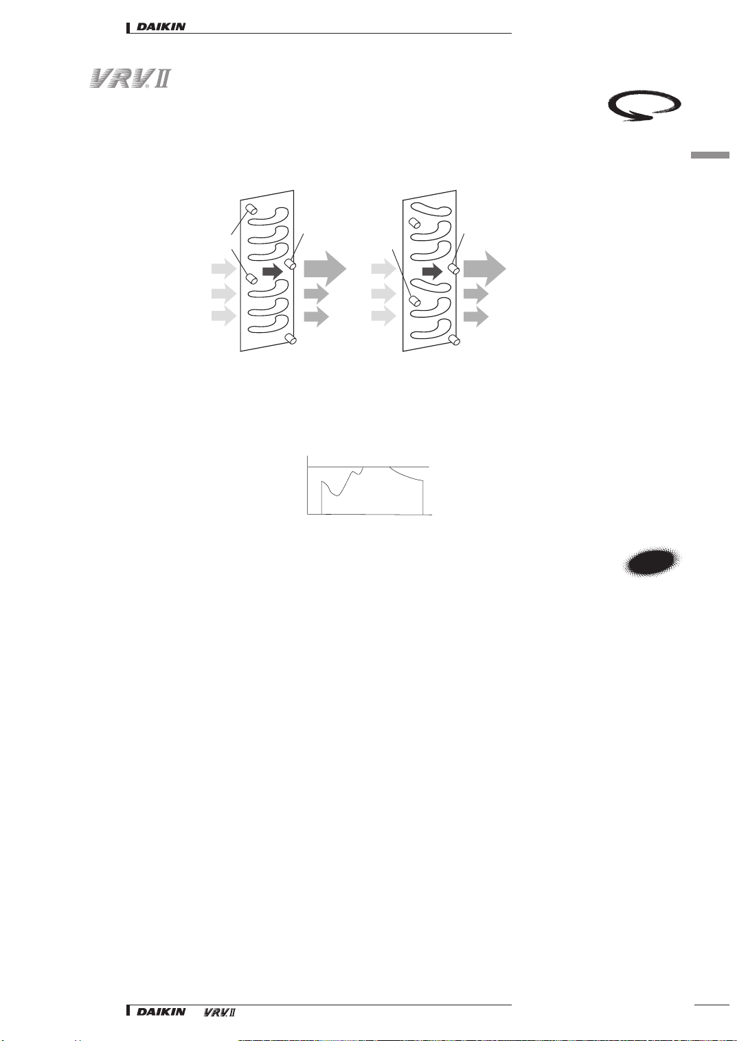
e-Pass heat exchanger
Optimization of the path layout of the heat exchanger prevents heat transferring from the overheated gas section towards the sub cooled liquid section
- a more efficient use of the heat exchanger.
First in the
industry
1
5
Current Model
out 45°C
in 85°C
27°C55°C
27°C
27°C
In cooling mode, the heat exchanger of the condensor is improved. This means an improvement of COP by 3%.
i-Demand function
The newly introduced current sensor minimizes the difference between the actual power consumption and the predefined power consumption.
Compact aero box
55°C
55°C
50°C
Power
consumption (KVV)
8:00
in 85°C
27°C43°C
27°C
27°C
12: 00 16: 00 20:00
Time
HD Typ e
out 45°C
37°C
60°C
55°C
N
W
E
Lower noise and savings in input power are achieved by stacking the inverter and control PCBs within a new and more compact ‘aero’ box.
• Systems • Introduction
9
• Introduction
6Main features
6-1 Creating maximum comfort
1
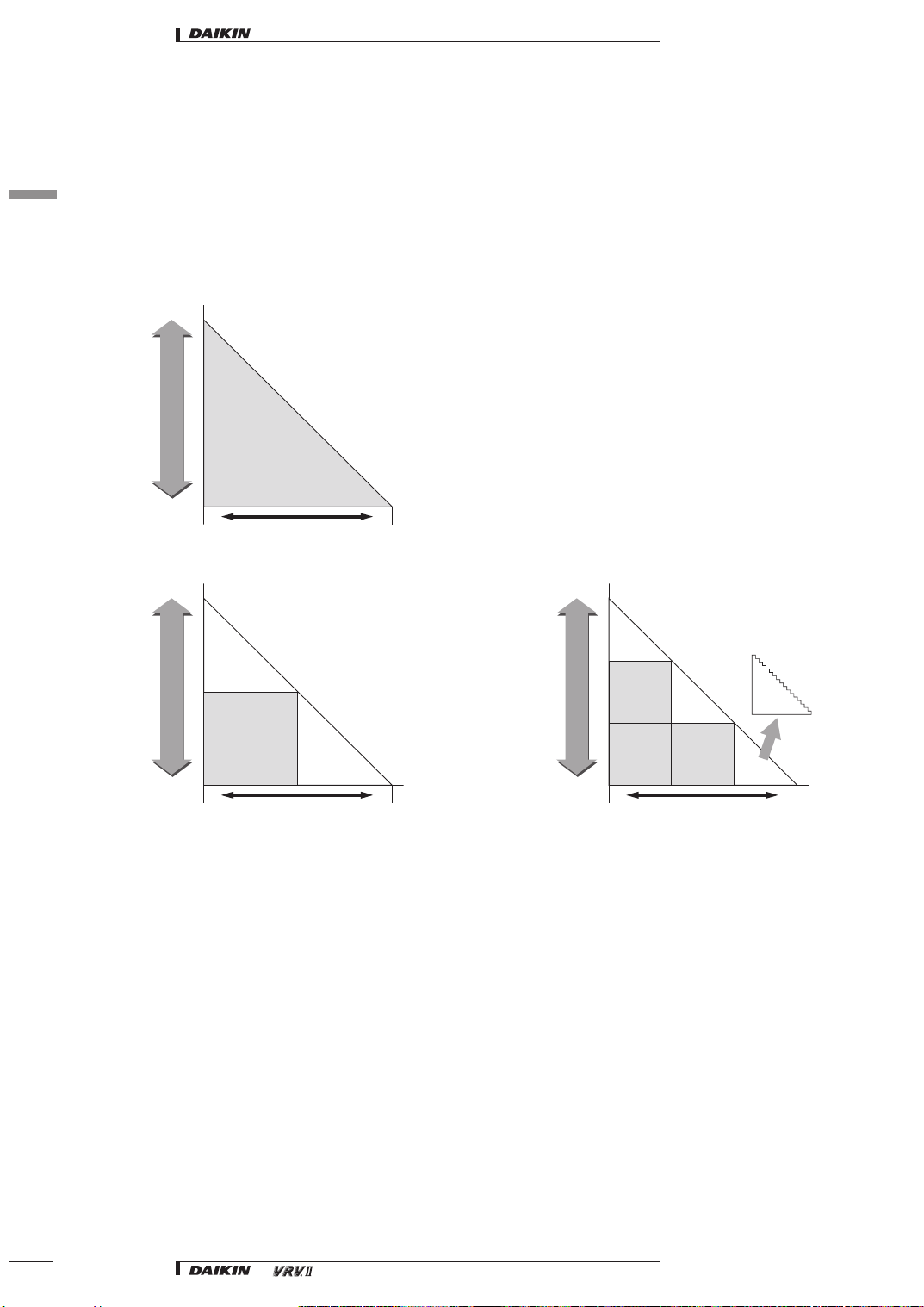
6-1-1 Inverter technology
6
The linear VRV system makes use of a variable Proportional Integral (PI) control system which uses refrigerant pressure sensors to give added control
over inverter and ON/OFF control compressors in order to abbreviate control steps into smaller units to provide precise control in both small and larger
areas.
This in turn enables individual control of up to 40 indoor units of different capacity and type at a ratio of 50~130 % in comparison with outdoor units
capacity. 5 HP outdoor units use inverter control compressors only.
5HP Outdoor Unit
100%
210Hz~52Hz
20 Steps
Compressor Capacity Control
Inverter
Control
24%
Large
8,10,12HP Outdoor Unit
100%
Nr. 1
Compressor
Inverter Control
Compressor Capacity Control
14%
Large
Nr. 2
Compressor
100% Operation
Load
210Hz~52Hz
+ Nr. 2 Compressor
29 Steps
Nr. 1
Compressor
Inverter Control
Load
Small
Small
14,16HP Outdoor Unit
100%
Nr. 1
Compressor
Inverter Control
Compressor Capacity Control
10%
Large
Nr. 3
Compressor
100% Operation
Nr. 2
Compressor
100% Operation
210Hz~52Hz
+ Nr. 2 + Nr. 3
Compressor
35 Steps
Nr. 1
Compressor
Inverter Control
Nr. 2
Compressor
100% Operation
Load
Inverter Control
210Hz~52Hz 20 steps
Nr. 1
Compressor
Inverter Control
Small
10
• Systems • Introduction
• Introduction
6Main features
6-1 Creating maximum comfort
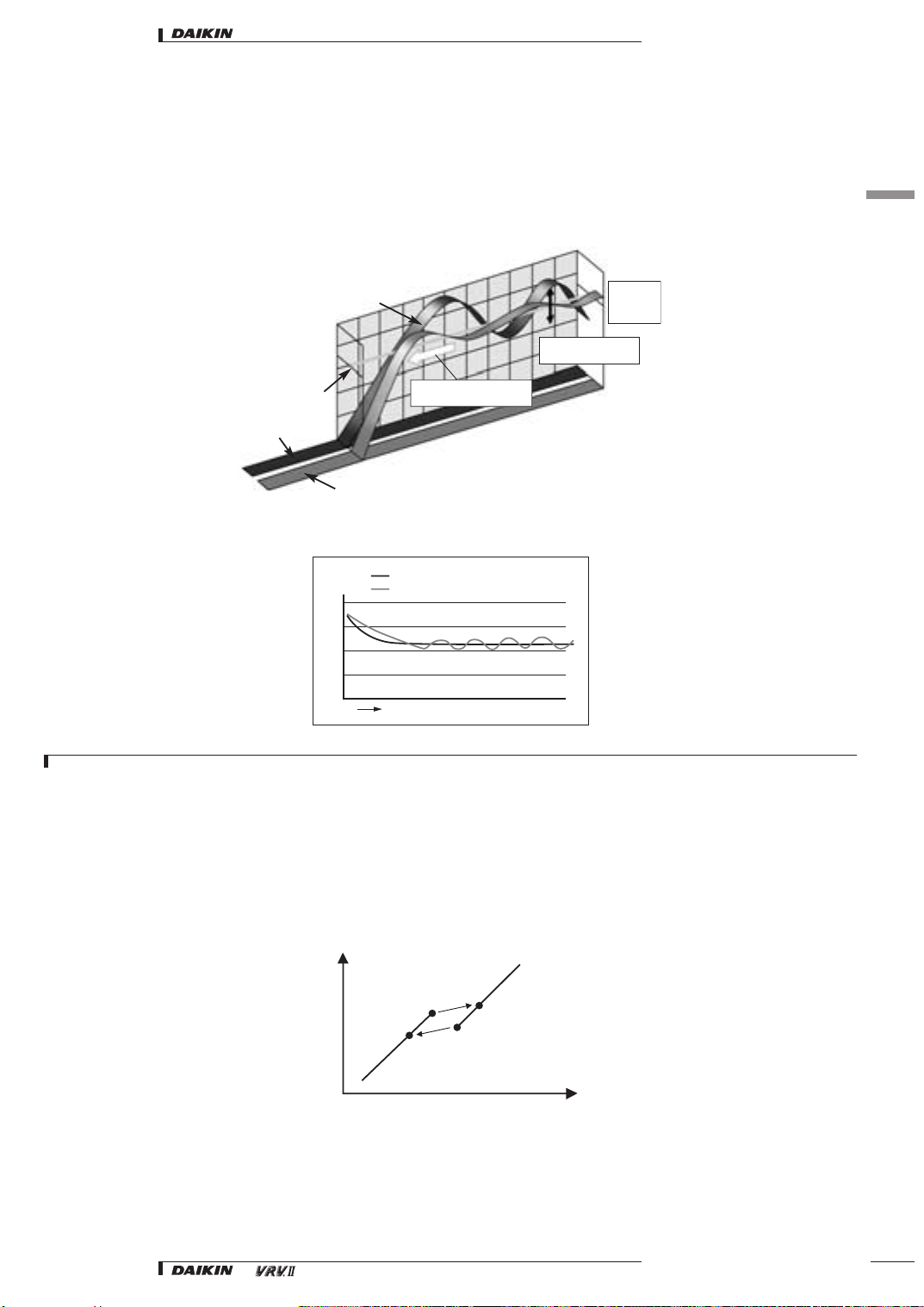
6-1-2 Smart control brings comfort
An electronic expansion valve, using PID control, continuously adjusts the refrigerant volume in respond to load variations of the indoor units. The VRV
system thus maintains comfortable room temperatures at a virtually constant level, without the temperature variations typical of conventional ON/OFF
control systems.
Keeps temperature stable
Slow start-up
Set point
Non inverter AC
Inverter AC
The thermostat can control stable room temperature at ± 0.5°C from set point.
Startup time educedby about 1/3
s
t
a
e
p
e
R
Cooling
VRV series (Daikin PID controls)
On/off controlled air conditioner (2.5HP)
Large temperature difference
s
e
l
c
y
c
d
l
o
c
d
n
a
t
o
h
Smaller
temperature
difference
1
6
Suction air temp.
Time
NOTE
1 the graph shows the data, measured in a test room assuming actual heating load.
6-1-3 Less frequent start/stop cycle
• The technique adopted by Daikin, of regulating the capacity using multiple compressors clearly results in minimum switching losses and power surges
because of the overlap in capacity and frequency
• Since Daikin utilises small 5HP inverter compressors, the influence of harmonics is less than that generated by a single large compressor
• The use of multiple compressors by Daikin also ensures a 50 % standby facility
•Smaller compressors are cheaper and faster to replace
60%
Capacity
50%
30 116 30+on 116+on
65%
55%
Frequency
• Systems • Introduction
11
• Introduction
6Main features
6-1 Creating maximum comfort
1
6-1-4 PID control
6
Proportional Integral Derivative control with an automatic capacity balancing circuit:
– enables the use of lengthy piping up to 100 meters (actual length)
– consists of two control systems:
1Oil control system that controls the refrigerant oil volume to prevent it from raising or backing up in the pipes
2 Refrigerant flow stabilization mechanism: prevents refrigerant drift, caused by level difference of indoor units in the same system.
6-1-5 Operation control of small capacity indoor units
If the operating frequency is minimal, the refrigerant pressure and outdoor temperature are detected, the number of control steps are calculated, and
capacity of outdoor unit heat exchanger (refrigerant accumulates in coils) and air flow of outdoor unit fans (controls pole change of the two fans) are
controlled.
If operating a small-capacity indoor unit, the bypass valve is controlled (ON/OFF), with capacity control being executed at a minimum of 14% for a 5HP
outdoor unit (when operating one 20-class indoor unit), or a minimum of 8% for 8 and 10HP outdoor units (when operating one 20-class indoor unit.
Minimum Frequency
(5HP Outdoor Unit: 30Hz)
(8/10HP Outdoor Unit: 30Hz)
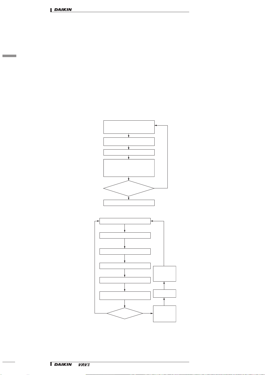
6-1-6 Control flow
Detection of Refrigerant Pressure and Outdoor
Operating Pressure Detection by Pressure Sensors
Calculation of Constant for Integral Control
Total capacity Decision by Multi-Variable P-Control
Temperature
Step Control Calculation
Capacity Control of Outdoor Unit
Heat Exchangers
Air Flow Control of Outdoor
Unit Fans
Are you operating a
small-capacity indoor unit?
Bypass Valve On/Off Control
Sampling Timer Count
Optimal Load Decision
Yes
Every T Seconds
Deviation (difference between
sensed pressure and desired value)
No
Outdoor Coil Capacity
Control Air Volume
Control by Outdoor
Unit Fan
12
Frequency Alteration of Inverter Compressor
On/Off of ON/OFF Compressor
No Yes
Minimum Frequency
• Systems • Introduction
Step Control
Calculation
Detection of
Refrigerant Pressure
and Outdoor
Temperature
 Loading...