

Daikin RXYQ72PYDN, RXYQ96PYDN, RXYQ120PYDN, RXYQ144PYDN, RXYQ168PYDN Installation Manual
...
INSTALLATION MANUAL
System air conditioner
English
Français
Español
RXYQ72PYDN
RXYQ96PYDN
RXYQ120PYDN
RXYQ144PYDN
RXYQ168PYDN
RXYQ192PYDN
RXYQ216PYDN
RXYQ240PYDN

<
If installed as a single unit
(Pattern 1)
1
≥3/8
≥3/8
1
2
(Pattern 2)
(Pattern 3)
1
≥2
≥11-3/4
>
≥11-3/4 ≥11-3/4
4
≥19-5/8
3
≥3-7/8
4
≥2
≥19-5/8
3
2
(Pattern 1)
≥3/8
(Pattern 2)
(Pattern 3)
<
When installed in serial
≥3/8
1
≥3/4
≥2
≥3-7/8
≥3/4
≥3-7/8
1
≥11-3/4
≥2
2
>
4
≥19-5/8
3
≥3-7/8
≥19-5/8
1
2
2
4
3
≥60
5
3
≥40
≥60
≥60
4
≥60
(in.)
≥40
≥40
≥7-7/8
1
≥7-7/8
1
≥15-3/4 ≥15-3/4
figure 1 figure 3figure 2
12
<3>
1
4
2
1
1
2
3-7/8
≥
3-7/8
≥
3-7/8
≥
5
3
figure 4 figure 6figure 5
1
3
24-7/8
30-1/8
4
1
3
4
6
2
5
3
1
4
2
3
5
2
30-1/8
A
B
29
figure 7 figure 8 figure 9 figure 10
≥
3-7/8
1
≥
3-7/8
4
3-7/8
≥
5
3
2
1
44
2
3
figure 11 figure 12
1
3
6
5
9
14
9
7
8
15
15
6
5
9
9
16
9
10
13
17
11
12
20
2
5
4
19
6
3
1
3
10
6
5
7
7
11
7
8
5
7
9
7
2
4
6
1
2
4
8
18
9
13
12
figure 13-1
figure 13-2
A
1
2
5
figure 14
34
1
B
2
figure 15 figure 16
D
16-2
16-1
C
1
2
1
3
4
7
1
5
6
1
4
8
16-3
11
2
2
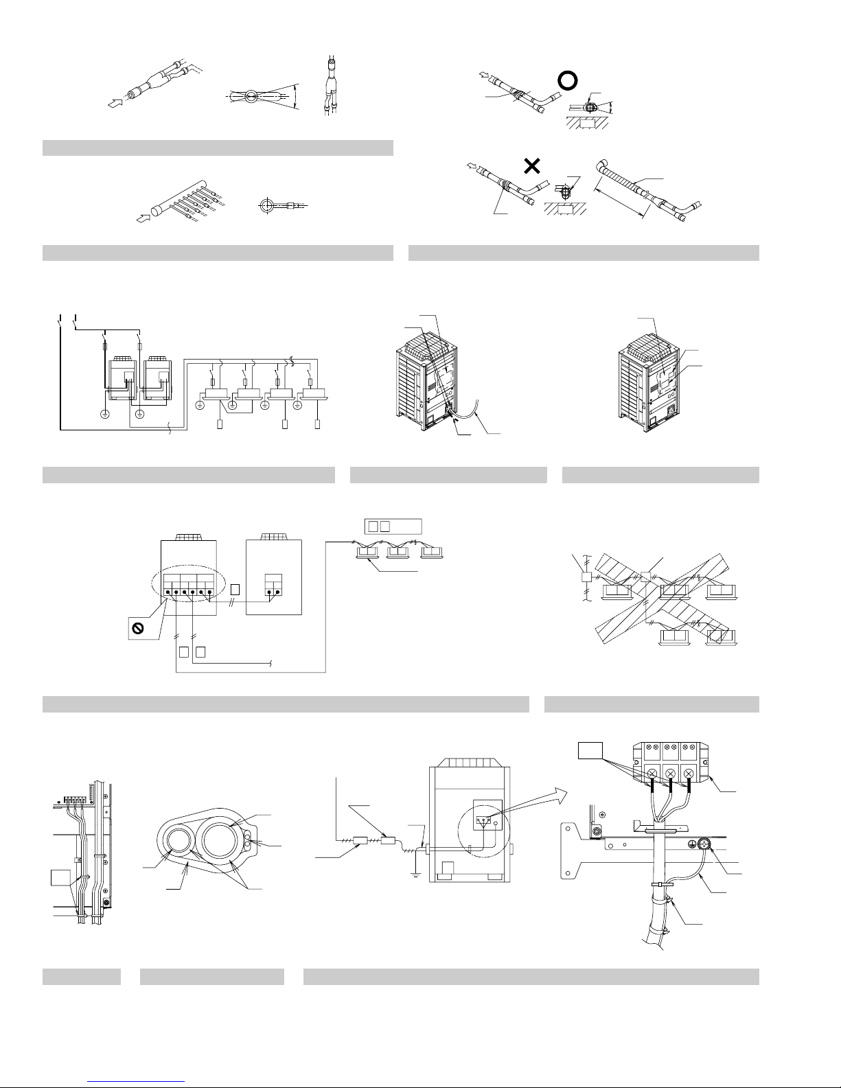
figure 17
figure 19
1
2
3
4
5
TO IN/D UNIT
F1 F2
3
4
6
1
3
A1P
TO OUT/D UNIT
TO MULTI UNIT
F1 F2
Q1 Q2
2
7
2
4
A1P
TO MULTI UNIT
Q1 Q2
figure 18-1
:
12
7
F1 F2 F1 F2 F1 F2
8
4
3
figure 18-2
1
5
1
2
3
2
F1 F2 F1 F2F1 F2
F1 F2 F1 F2
11
6
figure 20
1
(A1P)
2
3
1
2
figure 21 figure 23
5
figure 22
4
5
L1 L2 L3
1
6
3
4
2
7
4
8
7
15 15
11
1
2
10
12
9
1
3
2
4
: 19
: 20
6
5
14
8
9
10
11
12
13
16
F17
()
18
figure 24
figure 27
3
8
figure 25
2
4
6
5
7
1
figure 26
1
2
3
5
1
2
3
4
figure 28
1
2
6
3
4
2
5
figure 29 figure 30
3
1
4
5
6
7
8
12
13
9
10
2
: 15
()
: 16
: 17
: 18
11
14
19
9
figure 31
3
1
4
5
6
7
8
12
13
9
10
2
:
15
:
16
11
:
14
1
17
()
:
18
2
3
4
figure 32

RXYQ72PYDN
RXYQ96PYDN
RXYQ120PYDN
RXYQ144PYDN
RXYQ168PYDN
RXYQ192PYDN
RXYQ216PYDN
RXYQ240PYDN
CONTENTS
1. FIRST OF ALL.......................................................................... 1
1-1. Safety considerations........................................................1
1-2. Special notice of product...................................................2
1-3. Disposal requirements.......................................................3
2. INTRODUCTION......................................................................3
2-1. Combination ......................................................................3
2-2. Standard supplied accessories ......................................... 3
2-3. Option accessory...............................................................3
2-4. Technical and Electrical specifications.............................. 3
2-5. Main components..............................................................3
3. SELECTION OF LOCATION.................................................... 3
4. INSPECTING AND HANDLING THE UNIT.............................. 4
5. PLACING THE UNIT ................................................................4
6. REFRIGERANT PIPING ..........................................................5
6-1. Selection of piping material and
Refrigerant branching kit ...................................................5
6-2. Protection against contamination when installing pipes....5
6-3. Pipe connection................................................................. 5
6-4. Connecting the refrigerant piping ...................................... 5
6-5. Example of connection......................................................8
7. FIELD WIRING.......................................................................11
7-1. Power circuit, safety device and cable requirements ......11
7-2. Wiring Connection Example for Whole System...............11
7-3. Leading wire Procedure .................................................. 11
7-4. Transmission Wiring Connection Procedure................... 12
7-5. Power Wiring Connection Procedure ..............................12
7-6. Procedure for Wiring Inside Units....................................12
8. AIR TIGHT TEST AND VACUUM DRYING ...........................13
9. PIPE INSULATION................................................................. 13
10. CHECKING OF DEVICE AND
INSTALLATION CONDITIONS ..............................................14
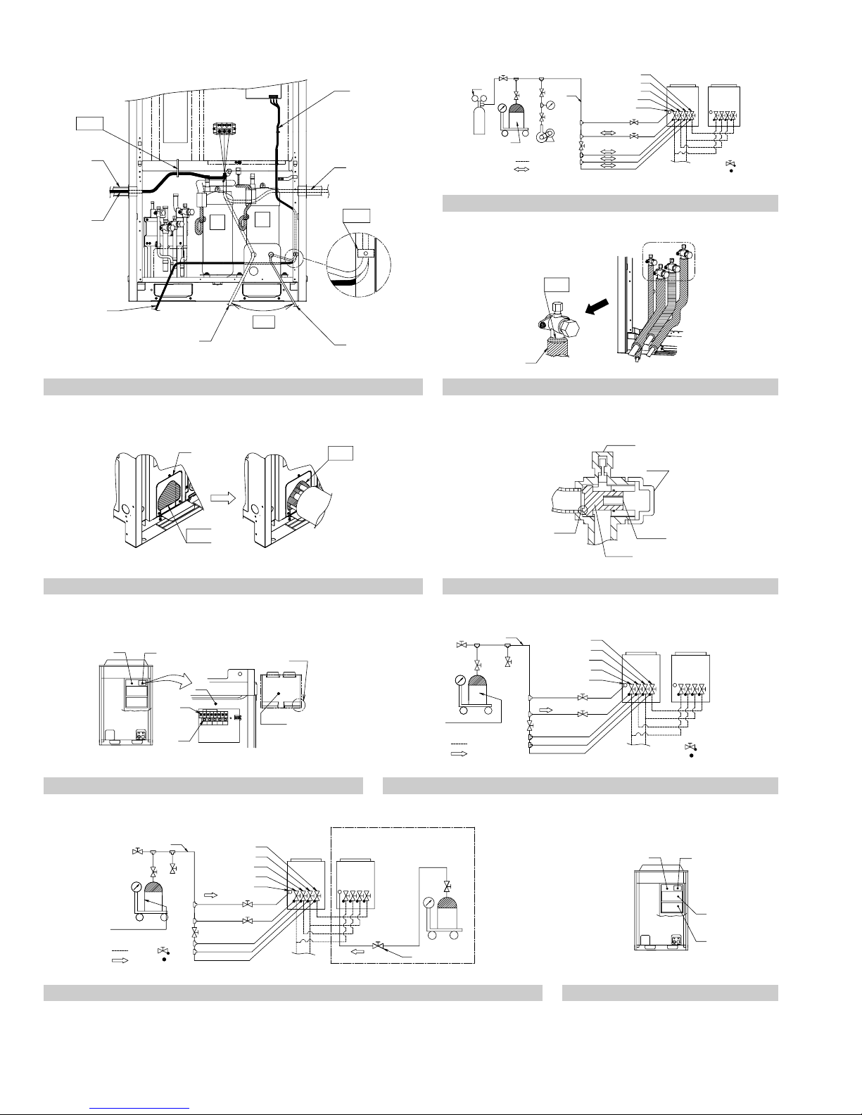
11. ADDITIONAL REFRIGERANT CHARGE AND
CHECK OPERATION............................................................. 14
11-1.Before working ...............................................................14
11-2.Procedure of Adding Refrigerant charging and
check operation ...............................................................15
12. ONSITE SETTINGS ............................................................... 18
13. TEST RUN .............................................................................18
13-1.Before test run................................................................18
13-2.Test Run......................................................................... 18
13-3.Checks After Test Run ...................................................18
14. CAUTION FOR REFRIGERANT LEAKS ...............................19
1. FIRST OF ALL
• This document is an installation manual for the Daikin RXYQ-P
Series VRV Inverter. Before installing the unit, read this manual thoroughly, and following the instructions contained in it.
After installation, do a test run to make sure the unit runs properly,
and then explain how to operate and take care of the unit to the customer, using the operation manual.
Lastly, make sure the customer keeps this manual, along with the
operation manual, in a safe place.
1-1 Safety considerations
Please read these “SAFETY CONSIDERATIONS” carefully before
installing air conditioning unit and be sure to install it correctly. After
completing the installation, make sure that the unit operates properly
during the start-up operation. Please instruct the customer on how to
operate the unit and keep it maintained.
Also, inform customers that they should store this installation manual
along with the operation manual for future reference.
This air conditioner comes under the term “appliances not accessible to
the general public”.
VRVIII System air conditioner Installation manual
〈Safety Precaution〉
VRV System is a class A product. In a domestic environment this product may cause radio interference in which case the user may be
required to take adequate measures.
Meaning of danger, warning, caution and note symbols.
DANGER .................... Indicates an imminently hazardous situa-
tion which,if not avoided, will result in death
or serious injury.
WARNING .................. Indicates a potentially hazardous situation
which, if not avoided, could result in death
or serious injury.
CAUTION.................... Indicates a potentially hazardous situation
which, if not avoided, may result in minor or
moderate injury. It may also be sued to
alert against unsafe practices.
NOTE.......................... Indicates a situation that may result in the
unit or property-damage-only accidents.
DANGER
• Refrigerant gas is heavier air and replaces oxygen. A massive
leak could lead to oxygen depletion, especially in basements,
and an asphyxiation hazard could occur leading to serious
injury or death.
• Do not ground units to water pipes, telephone wires or lightning rods because incomplete grounding could cause a severe shock hazard resulting in severe injury or death, and to
gas pipes because a gas leak could result in an explosion
which could lead to severe injury or death.
• If the refrigerant gas leaks during installation, ventilate the
area immediately.
Refrigerant gas may produce toxic gas if it comes in contact with fire
such as from a fan, heater, stove or cooking device. Exposure to this
gas could cause severe injury or death.
• After completing the installation work, check that the refrigerant gas does not leak.
Refrigerant gas may produce toxic gas if it comes in contact with fire
such as from a fan, heater, stove or cooking device. Exposure to this
gas could cause severe injury or death.
• Do not install unit in an area where flammable materials are
present due to risk of explosion resulting in serious injury or
death.
• Safely dispose of the packing materials.
Packing materials, such as nails and other metal or wooden parts,
may cause stabs or other injuries.
Tear apart and throw away plastic packaging bags so that children will
not play with them. Children playing with plastic bags face the danger
of death by suffocation.
WARNING
• Ask your dealer or qualified personnel to carry out installation
work. Do not try to install the unit by yourself.
Improper installation may result in water leakage, electric shocks or fire.
• Perform installation work in accordance with this installation
manual.
Improper installation may result in water leakage, electric shocks or fire.
• When installing the unit in a small room, take measures
against to keep refrigerant concentration from exceeding allowable safety limits in the event of refrigerant leakage.
Contact the place of purchase for more information. Excessive refrigerant in a closed ambient can lead to oxygen deficiency.
• Be sure to use only the specified accessories and parts for installation work.
Failure to use the specified parts may result in water leakage, electric
shocks, fire or the unit falling.
English 1

• Install the air conditioner on a foundation strong enough to
withstand the weight of the unit.
A foundation of insufficient strength may result in the unit falling and
causing injuries.
• Carry out the specified installation work after taking into account strong winds, typhoons or earthquakes.
Improper installation work may result in the unit falling and causing
accidents.
• Make sure that a separate power supply circuit is provided for
this unit and that all electrical work is carried out by qualified
personnel according to local laws and regulations and this installation manual.
An insufficient power supply capacity or improper electrical construction may lead to electric shocks or fire.
• Make sure that all wiring is secured, the specified wires and used,
and no external forces act on the terminal connections or wires.
Improper connections or installation may result in fire.
• When wiring the power supply and connecting the remote
controller wiring and transmission wiring, position the wires
so that the electric parts box lid can be securely fastened.
Improper positioning of the electric parts box lid may result in electric
shocks, fire or the terminals overheating.
• Before touching electrical parts, turn off the unit.
• Securely install the outside unit terminal cover (panel).
If the terminal cover (panel) is not installed properly, dust or water
may enter the outside unit and fire or electric shock may result.
• When installing or relocating the system, be sure to keep the
refrigerant circuit free from substances other than the specified refrigerant (R410A), such as air.
Any presence of air or other foreign substance in the refrigerant circuit causes an abnormal pressure rise or rupture, resulting in injury.
• Do not reconstruct or change the settings of the protection
devices.
If the pressure switch, thermal switch, or other protection device is
shorted and operated forcibly, or parts other than those specified by
Daikin are used, fire or explosion may result.
• Do not touch the switch with wet fingers.
Touching a switch with wet fingers can cause electric shock.
• Do not allow children to play on or around the unit as they
could be injured.
• Refrigerant pipes may be very hot or very cold during or immediately after operation.
Touching them could result in burns or frostbite. To avoid injury give
the pipes time to return to normal temperature or, if you must touch
them, be sure to wear proper gloves.
• Be sure to install a ground fault circuit interrupter.
Failure to install an earth leakage breaker may result in electric
shocks, or fire.
CAUTION
• While following the instructions in this installation manual,
install drain piping in order to ensure proper drainage and insulate piping in order to prevent condensation.
Improper drain piping may result in water leakage and property damage.
• Be very careful about product transportation.
• Do not touch the refrigerant pipes during and immediately after operation.
During and immediately after operation, the refrigerant pipes may be
hot and may be cold, depending on the condition of the refrigerant
flowing through the refrigerant piping, compressor, and other refrigerant cycle parts. Your hands may suffer burns or frostbite if you touch
the refrigerant pipes.
• Do not turn off the power immediately after stopping operation.
Always wait at least five minutes before turning off the power. Otherwise, water leakage and trouble may occur.
• Do not use a charging cylinder.
Using a charging cylinder may cause the refrigerant to deteriorate.
• The refrigerant R410A requires strict cautions for keeping the
system clean, dry and tight.
A. Clean and dry
Foreign materials (including mineral oils such as SUNISO oil or
moisture) should be prevented from getting mixed into the system.
B. Tight
R410A does not contain any chlorine, does not destroy the ozone
layer, and does not reduce the earth’s protection against harmful
ultraviolet radiation.
R410A can contribute slightly to the greenhouse effect if it is
released. Therefore we should take special attention to check the
tightness of the installation.
Read the chapter “Refrigerant piping” carefully and follow these
procedures correctly.
• Since R410A is a mixed refrigerant, the required additional refrigerant must be charged in its liquid state. (If the refrigerant
is charged in a state of gas, its composition changes and the
system will not work properly.)
The indoor unit is for R410A. See the catalog for indoor unit models
which can be connected.
(Normal operation is not possible when connected to other units.)
• Remote controller (wireless kit) transmitting distance can result shorter than expected in rooms with electronic fluorescent lamps. (inverter or rapid start types)
Install the indoor unit as far away from fluorescent lamps as possible.
• Install in a machine room that has no water drops.
This unit is for indoor use.
• Do not install the air conditioner in the following locations:
(a) where a mineral oil mist or an oil spray or vapor is produced, for
example in a kitchen
Plastic parts may deteriorate and fall off or result in water leakage.
(b) where corrosive gas, such as sulfurous acid gas, is produced
Corroding copper pipes or soldered parts may result in refrigerant
leakage.
(c) near machinery emitting electromagnetic waves
Electromagnetic waves may disturb the operation of the control
system and result in a malfunction of the unit.
(d) where flammable gas may leak, where there are carbon fiber or
ignitable dust suspensions in the air, or where volatile flammables
such as thinner or gasoline are handled.
Operating the unit in such conditions may result in fire.
• Make sure to provide for adequate measures in order to prevent
that the outside unit be used as a shelter by small animals.
Small animals making contact with electrical parts can cause malfunctions, smoke or fire. Please instruct the customer to keep the
area around the unit clean.
NOTE
• Install the indoor and outside units, power supply wires and
transmission wires at least 3.5ft. away from televisions or radios
in order to prevent image interference or noise.
(Depending on the radio waves, a distance of 3.5ft. may not be sufficient to eliminate the noise.)
• Dismantling of the unit, treatment of the refrigerant, oil and
eventual other parts, should be done in accordance with the
relevant local and national regulations.
• Do not use the following tools that are used with conventional
refrigerants. (Gauge manifold, charge hose, gas leak detector,
reverse flow check valve, refrigerant charge base, vacuum
gauge, refrigerant recovery equipment.)
If the conventional refrigerant and refrigerator oil are mixed in the
R410A, the refrigerant may deteriorate.
1-2 Special notice of product
[CLASSIFICATION]
This air conditioner comes under the term “appliances not accessible to
the general public”.
[REFRIGERANT]
VRVIII System use R410A refrigerant.
• The refrigerant R410A requires strict cautions for keeping the sys-
tem clean, dry and tight.
Read the chapter “REFRIGERANT PIPING” carefully and follow
these procedures correctly.
2 English
A. Clean and dry
Foreign materials (including mineral oils such as SUNISO oil or
moisture) should be prevented from getting mixed into the system.
B. Tight
Take care to keep the system tight when installing.
R410A does not contain any chlorine, does not destroy the ozone
layer, and does not reduce the earth’s protection against harmful
ultraviolet radiation.
R410A can contribute slightly to the greenhouse effect if it is
released.
• Since R410A is a mixed refrigerant, the required additional refrigerant
must be charged in its liquid state. If the refrigerant is charged in a state
of gas, its composition changes and the system will not work properly.
[DESIGN PRESSURE]
Since design pressure is 478 psi, the wall thickness of pipes should be
more carefully selected in accordance with the relevant local and
national regulations.
1-3 Disposal requirements
Dismantling of the unit, treatment of the refrigerant, oil and eventual
other parts, should be done in accordance with the relevant local and
national regulations.
2. INTRODUCTION
• RXYQ-P series are designed for outdoor installation and used for
cooling and heating applications.
• The indoor units that combined with RXYQ-P system for air conditioning are Daikin VRV series indoor units that compatible with
R410A. To learn which indoor units are compatible with R410A, refer
to the product catalogs. To combine with other refrigerant indoor unit
will cause malfunction.
2-1 Combination
The system name and that independent units are as follows.
〈
The system name
RXYQ72PYDN ..............RXYQ72PYDN
RXYQ96PYDN ..............RXYQ96PYDN
RXYQ120PYDN ............RXYQ120PYDN
RXYQ144PYDN ............RXYQ72PYDN RXYQ72PYDN
RXYQ168PYDN ............RXYQ72PYDN RXYQ96PYDN
RXYQ192PYDN ............RXYQ72PYDN RXYQ120PYDN
RXYQ216PYDN ............RXYQ96PYDN RXYQ120PYDN
RXYQ240PYDN ............RXYQ120PYDN RXYQ120PYDN
• The indoor units can be installed in the following range.
〈Outside unit〉 〈Total capacity index of indoor units〉
RXYQ72PYDN ..............36 ~ 93.5
RXYQ96PYDN ..............48 ~ 124.5
RXYQ120PYDN ............60 ~ 156
RXYQ144PYDN ............72 ~ 187
RXYQ168PYDN ............84 ~ 218
RXYQ192PYDN ............96 ~ 249.5
RXYQ216PYDN ............108 ~ 280.5
RXYQ240PYDN ............120 ~ 312
• For installing the 2 units multi system, Outside unit multi connection
piping kit "BHFP22P100U" are required.
• If the total capacity of the connected indoor units exceeds the capacity of the outside unit, cooling and heating performance may drop
when running the indoor units. See the capacity table in the Engineering Data Book for details.
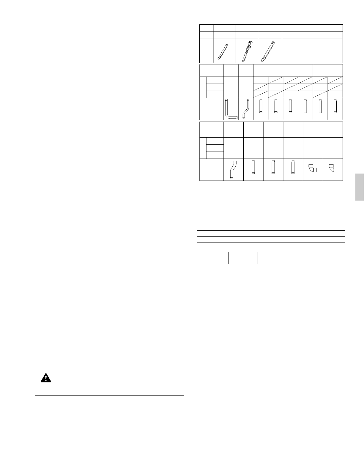
2-2 Standard supplied accessories
Confirm the following accessories are included. The storage location of
the accessories is shown in figure 1.
NOTE
Do not throw away any of the accessories until installation is complete.
They are needed for installation work.
〉
〈Independent units〉
Name
Quantity
Shape
Name
72P type
96P type
Quantity
120P type
Shape
Name
72P type
96P type
Quantity
120P type
Shape
Clamp(1)
9 pcs.
(Small)
Liquid side
accessory
pipe (1)
1 pc.
High side
equalizer
accessory
pipe (1)
1 pc.
Clamp(2)
2 pcs.
Liquid side
accessory
pipe (2)
1 pc.
Clamp(3)
1 pc.
• Operation manual
• Installation manual
• "REQUEST FOR THE INDICATON"
• "ADDITIONAL REF. CHARGE" label
(Large)
Gas side accessory pipe (1)
1 pc.
1 pc.
φ3/4 φ7/8
High side
equalizer
accessory
pipe (2)
Low side
equalizer
accessory
pipe (1)
1 pc.
φ3/4 φ1 φ3/4
Low side
equalizer
accessory
pipe (2)
1 pc.
O.D φ1 I.D φ1
Manuals, etc.
1 pc. about each item
label (Installation records)
Gas side accessory
pipe (2)
1 pc.
1 pc.
1 pc.
φ1 φ1-1/8 φ7/8
L type
accessory
joint (1)
1 pc. 1 pc.
1 pc.
φ1
L type
accessory
joint (2)
2 pcs.
(Refer to figure 1)
1. Clamps, Manuals, etc.
2. Accessory pipes
2-3 Option accessory
To install the outside units, the following optional parts are also required.
To select an optimum kit, refer to “6. REFRIGERANT PIPING”.
• Outside unit multi connection piping kit
Number of outside units connected 2 units
Kit name BHFP22P100U
• Refrigerant branching kit
REFNET header KHRP26M22H KHRP26M33H KHRP26M72H
REFNET joint KHRP26M22T KHRP26M33T
KHRP26M72TU KHRP26M73TU
—
Make sure that any separately purchased accessories are designed for
use with R410A.
2-4 Technical and Electrical specifications
Refer to the Engineering Data Book for the complete list of specifications.
2-5 Main components
For main components and function of the main components, refer to the
Engineering Data Book.
3. SELECTION OF LOCATION
Select a location for installation that meets the following conditions and
get the customer’s permission.
1.
Select the location of the unit in such a way that neither the discharged air nor the sound generated by the unit disturb anyone.
2.
The foundation is strong enough to support the weight of the unit and
the floor is flat to prevent vibration and noise generation.
3.
The piping length between the outside unit and the indoor unit may
not exceed the allowable piping length.
(Refer to “6. REFRIGERANT PIPING”)
4.
Locations where the unit’s suction vent and outlet vent do not generally face the wind.
Wind blowing directly into the suction or outlet vents will interfere with
the unit’s operation.
If necessary, install some kind of obstruction to block the wind.
5.
The space around the unit is adequate for servicing and the minimum space for air inlet and air outlet is available.
(See the “Installation Space Examples” for the minimum space
requirements.)
English 3
Installation Space Examples
• The installation space requirement shown in figure 2 is a reference
for cooling operation when the outdoor temperature is 95°F.
If the design outdoor temperature exceeds 95°F or the heat load
exceeds maximum capacity in all the outside unit, take an even large
space on the intake shown in figure 2.
• During installation, install the units using the most appropriate of the
patterns shown in figure 2 for the location in question, taking into
consideration human traffic and wind.
• If the number of units installed is more than that shown in the pattern
in figure 2, install the units so there are no short circuits.
• As regards space in front of the unit, consider the space needed for
the local refrigerant piping when installing the units.
• If the work conditions in figure 2 do not apply, contact your dealer or
Daikin directly.
(Refer to figure 2)
1. Front side
2. No limit to wall height
3. Service space of front side
4. Service space of suction side
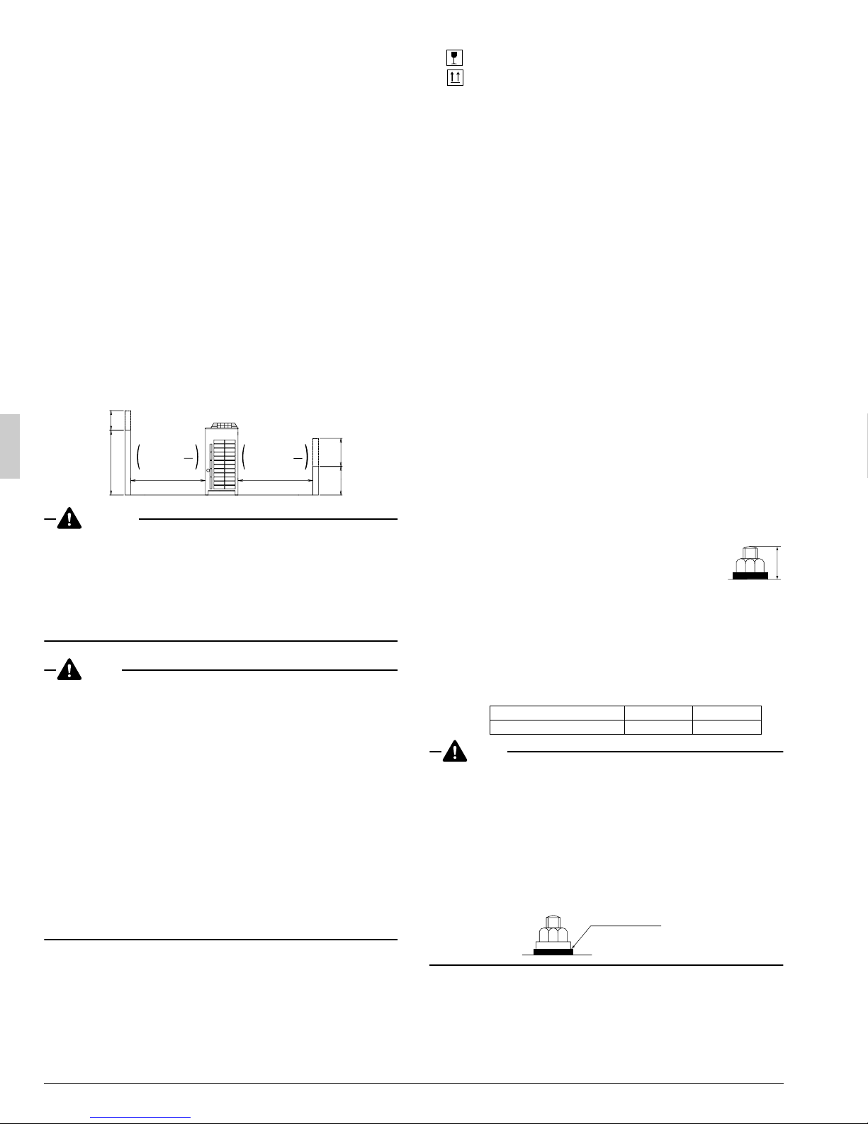
For Patterns 1 and 2 in figure 2 :
• Wall height for front side – no higher than 59 in.
• Wall height on the suction side – no higher than 19-5/8 in.
• Wall height for sides – no limit.
• If the height is exceeded the above, calculate h1 and h2 shown in
the figure below, and add h2/2 to the service space of front side
and h1/2 to the service space of suction side.
h2
<Front side> <Suction side>
59
DANGER
• Do not install unit in an area where flammable materials are
present due to risk of explosion resulting in serious injury or
death.
• Refrigerant gas in heavier air and replaces oxygen. A massive
leak could lead to oxygen depletion, especially in basements,
and an asphyxiation hazard could occur leading to serious injury or death.
Refer to the chapter “CAUTION FOR REFRIGERANT LEAKS”
NOTE
1.
An inverter air conditioner may cause electronic noise generated
from AM broadcasting. Examine where to install the main air conditioner and electric wires, keeping proper distances away from stereo
equipment, personal computers, etc.
Particularly for locations with weak reception, ensure there is a distance of at least 10 ft for indoor remote controllers, place power wiring and transmission wiring in conduits, and ground the conduits.
(Refer to figure 3)
1. Indoor unit
2. Branch switch, overcurrent breaker
3. Remote controller
4. COOL/HEAT selector
5. Personal computer or radio
2.
When installing in locations where there is heavy snowfall, implement the following snow measures.
• Ensure the base is high enough that intakes are not clogged by
snow.
• Remove the rear intake grille to prevent snow from accumulating
on the fins.
or more
2
h2
19 - 5/8 +
Service
space
or more
h1
+
2
h1
19-5/8
1.
Fragile, handle the unit with care.
Keep the unit upright in order to avoid compressor damage.
2.
Decide on the transportation route.
3.
If a forklift is to be used, pass the forklift arms through the large openings on the bottom of the unit. (Refer to figure 4)
4.
If hanging the unit, use a cloth sling to prevent damaging the unit.
Keeping the following points in mind, hang the unit following the procedure shown in figure 5.
• Use a sling sufficiently strong to hold the mass of the unit.
• Use 2 belts of at least 27 ft long.
• Place extra cloth or boards in the locations where the casing
comes in contact with the sling to prevent damage.
• Hoist the unit making sure it is being lifted at its center of gravity.
5.
After installation, remove the transportation clasp (yellow) attached
to the large openings. (Refer to figure 4)
(Refer to figure 4)
1. Packaging material
2. Forklift
3. Removal of shipping brackets
4. Shipping bracket (Remove the screws.)
(Refer to figure 5)
1. Belt sling
2. Wear plate
5. PLACING THE UNIT
• Make sure the unit is installed level on a sufficiently strong base to
prevent vibration and noise. (Refer to figure 6)
• The base should support the unit with the extent larger than hatched
area in figure 7.
If protective rubber is to be attached, attach it to the whole face of the
base.
• The height of the base should be at least 5-7/8 in. from the floor.
• Secure the unit to its base using foundation bolts. (Use four commer-
cially available M12-type foundation bolts, nuts, and washers.)
• The foundation bolts should be inserted 13/16 in..
(Refer to figure 6)
1. Independent base (four corner type)
2. Independent base (with center support type)
3. Beam base (Horizontal)
4. Beam base (Vertical)
5. Center of the product
(Refer to figure 7)
1. Foundation bolt point (φ9/16 in. dia, : 4positions)
2. (Depth of product)
3. (Inner dimension of the base)
4. (Outer dimension of the base)
Model A (in.) B (in.)
72 · 96 · 120P type 48-13/16 43-3/8
NOTE
• There are restrictions on the refrigerant pipe connecting order
between outside unit in the case of the multi system.
See “2-1 Combination” for detail.
• When installing on a roof, make sure the roof floor is strong enough
and be sure to water-proof all work.
• Make sure the area around the machine drains properly by setting up
drainage grooves around the foundation.
Drain water is sometimes discharged from the outside unit when it is
running.
• For anti-corrosion type, use nuts with resin washers. If the paint on
nut connections comes off, the anti-corrosion effect may decrease.
Resin washers
13/16 in.
4. INSPECTING AND HANDLING THE UNIT
• At delivery, the package should be checked and any damage should
be reported immediately to the carrier claims agent.
• When handling the unit, take into account the following :
4 English
 Loading...