

Daikin RXP20M5V1B, RXP25M5V1B, RXP35M5V1B, ARXP20M5V1B, ARXP25M5V1B Installation manuals
...
Installation manual
R32 split series
RXP20M5V1B
RXP25M5V1B
RXP35M5V1B
Installation manual
R32 split series
Installationsanleitung
R32 Split-Baureihen
Manuel d'installation
Série Split R32
Montagehandleiding
R32 Split-reeks
Manual de instalación
Serie Split R32
Manuale d'installazione
Serie Split R32
Εγχειρίδιο εγκατάστασης
Σειρά split R32
Manual de instalação
Série split R32
Руководство по монтажу
Серия сплит-систем с хладагентом R32
English
Deutsch
Français
Nederlands
Español
Italiano
Ελληνικά
Portugues
русский
ARXP20M5V1B
ARXP25M5V1B
ARXP35M5V1B
Montaj kılavuzu
R32 split serisi
Türkçe
Directivelor, cu amendamentele respective.
<A>
<B>
<C>
DEKRA (NB0344)
2159619.0551-EMC
DAIKIN.TCF.032D2/12-2017
Direktive z vsemi spremembami.
Direktiivid koos muudatustega.
Директиви, с техните изменения.
Direktyvose su papildymais.
Direktīvās un to papildinājumos.
Smernice, v platnom znení.
18192021222324
Direktiver, med senere ændringer.
Direktiv, med företagna ändringar.
Direktiver, med foretatte endringer.
10111213141516
Directives, as amended.
Direktiven, gemäß Änderung.
deklaruje na własną i wyłączną odpowiedzialność, że urządzenia, których ta deklaracja dotyczy:
declară pe proprie răspundere că echipamentele la care se referă această declaraţie:
z vso odgovornostjo izjavlja, da je oprema naprav, na katero se izjava nanaša:
kinnitab oma täielikul vastutusel, et käesoleva deklaratsiooni alla kuuluv varustus:
декларира на своя отговорност, че оборудването, за коeто се отнася тази декларация:
visiška savo atsakomybe skelbia, kad įranga, kuriai taikoma ši deklaracija:
ar pilnu atbildību apliecina, ka tālāk aprakstītās iekārtas, uz kurām attiecas šī deklarācija:
vyhlasuje na vlastnú zodpovednosť, že zariadenie, na ktoré sa vzťahuje toto vyhlásenie:
tamamen kendi sorumluluǧunda olmak üzere bu bildirinin ilgili olduǧu donanımının aşaǧıdaki gibi olduǧunu beyan eder:
17
18
19
20
21
22
23
24
25
megfelelnek az alábbi szabvány(ok)nak vagy egyéb irányadó dokumentum(ok)nak, ha azokat előírás szerint használják:
spełniają wymogi następujących norm i innych dokumentów normalizacyjnych, pod warunkiem że używane są zgodnie z naszymi instrukcjami:
sunt în conformitate cu următorul (următoarele) standard(e) sau alt(e) document(e) normativ(e), cu condiţia ca acestea să fie utilizate în conformitate cu
instrucţiunile noastre:
skladni z naslednjimi standardi in drugimi normativi, pod pogojem, da se uporabljajo v skladu z našimi navodili:
on vastavuses järgmis(t)e standardi(te)ga või teiste normatiivsete dokumentidega, kui neid kasutatakse vastavalt meie juhenditele:
съответстват на следните стандарти или други нормативни документи, при условие, че се използват съгласно нашите инструкции:
atitinka žemiau nurodytus standartus ir (arba) kitus norminius dokumentus su sąlyga, kad yra naudojami pagal mūsų nurodymus:
tad, ja lietoti atbilstoši ražotāja norādījumiem, atbilst sekojošiem standartiem un citiem normatīviem dokumentiem:
sú v zhode s nasledovnou(ými) normou(ami) alebo iným(i) normatívnym(i) dokumentom(ami), za predpokladu, že sa používajú v súlade snašim
návodom:
161718192021222324
ürünün, talimatlarımıza göre kullanılması koşuluyla aşağıdaki standartlar ve norm belirten belgelerle uyumludur:
25
Directives, telles que modifiées.
010203040506070809
Değiştirilmiş halleriyle Yönetmelikler.
25
Direktiivejä, sellaisina kuin ne ovat muutettuina.
v platném znění.
Smjernice, kako je izmijenjeno.
irányelv(ek) és módosításaik rendelkezéseit.
z późniejszymi poprawkami.
17
Richtlijnen, zoals geamendeerd.
Directivas, según lo enmendado.
Direttive, come da modifica.
Οδηγιών, όπως έχουν τροποποιηθεί.
Directivas, conforme alteração em.
*
**
както е изложено в <A> и оценено положително от <B>
съгласно Сертификата<C>.
kaip nustatyta <A> ir kaip teigiamai nuspręsta <B> pagal
Sertifikatą<C>.
kā norādīts <A> un atbilstoši <B> pozitīvajam vērtējumam
saskaņā ar sertifikātu<C>.
ako bolo uvedené v <A> a pozitívne zistené <B> vsúlade
s osvedčením<C>.
<A>’da belirtildiği gibi ve <C>Sertifikasına göre <B>
tarafından olumlu olarak değerlendirildiği gibi.
Директив со всеми поправками.
21Забележка*
22Pastaba*
23Piezīmes*
24Poznámka*
25Not*
Daikin Europe N.V. je pooblaščen za sestavo datoteke s tehnično mapo.
Daikin Europe N.V. on volitatud koostama tehnilist dokumentatsiooni.
Daikin Europe N.V. е оторизирана да състави Акта за техническа конструкция.
Daikin Europe N.V. yra įgaliota sudaryti šį techninės konstrukcijos failą.
Daikin Europe N.V. ir autorizēts sastādīt tehnisko dokumentāciju.
Spoločnosť Daikin Europe N.V. je oprávnená vytvoriť súbor technickej konštrukcie.
Daikin Europe N.V. Teknik Yapı Dosyasını derlemeye yetkilidir.
19**
20**
21**
22**
23**
24**
25**
a(z) <A> alapján, a(z) <B> igazolta a megfelelést, a(z)
<C>tanúsítvány szerint.
zgodnie z dokumentacją <A>, pozytywną
opinią <B> i Świadectwem<C>.
aşa cum este stabilit în <A> şi apreciat pozitiv de<B>
în conformitate cu Certificatul<C>.
kot je določeno v <A> in odobreno s strani <B>
vskladu scertifikatom<C>.
nagu on näidatud dokumendis <A> ja heaks kiidetud
<B> järgi vastavalt sertifikaadile<C>.
16Megjegyzés*
17Uwaga*
18Notă*
19Opomba*
20Märkus*
Machinery 2006/42/EC
Low Voltage 2014/35/EU
enligt <A> och godkänts av <B> enligt
Certifikatet<C>.
som det fremkommer i <A> og gjennom positiv
bedømmelse av <B> ifølge Sertifikat<C>.
jotka on esitetty asiakirjassa <A> ja jotka <B>
on hyväksynyt Sertifikaatin<C> mukaisesti.
jak bylo uvedeno v <A> a pozitivně zjištěno
<B> vsouladu sosvědčením<C>.
kako je izloženo u <A> i pozitivno ocijenjeno odstrane
Electromagnetic Compatibility 2014/30/EU
заявляет, исключительно под свою ответственность, что оборудование, к которому относится настоящее заявление:
erklærer under eneansvarlig, at udstyret, som er omfattet af denne erklæring:
deklarerar i egenskap av huvudansvarig, att utrustningen som berörs av denna deklaration innebär att:
erklærer et fullstendig ansvar for at det utstyr som berøres av denne deklarasjon innebærer at:
ilmoittaa yksinomaan omalla vastuullaan, että tämän ilmoituksen tarkoittamat laitteet:
prohlašuje ve své plné odpovědnosti, že zařízení, k němuž se toto prohlášení vztahuje:
izjavljuje pod isključivo vlastitom odgovornošću da oprema na koju se ova izjava odnosi:
teljes felelőssége tudatában kijelenti, hogy a berendezések, melyekre e nyilatkozat vonatkozik:
09
10
11
12
13
14
15
16
estão em conformidade com a(s) seguinte(s) norma(s) ou outro(s) documento(s) normativo(s), desde que estes sejam utilizados de
acordo com as nossas instruções:
соответствуют следующим стандартам или другим нормативным документам, при условии их использования согласно нашим инструкциям:
overholder følgende standard(er) eller andet/andre retningsgivende dokument(er), forudsat at disse anvendes i henhold til vore instrukser:
respektive utrustning är utförd i överensstämmelse med och följer följande standard(er) eller andra normgivande dokument, under förutsättning att
användning sker i överensstämmelse med våra instruktioner:
respektive utstyr er i overensstemmelse med følgende standard(er) eller andre normgivende dokument(er), under forutssetning av at disse brukes i
henhold til våre instrukser:
vastaavat seuraavien standardien ja muiden ohjeellisten dokumenttien vaatimuksia edellyttäen, että niitä käytetään ohjeidemme mukaisesti:
za předpokladu, že jsou využívány v souladu s našimi pokyny, odpovídají následujícím normám nebo normativním dokumentům:
08091011121314
u skladu sa slijedećim standardom(ima) ili drugim normativnim dokumentom(ima), uz uvjet da se oni koriste u skladu s našim uputama:
15
ob upoštevanju določb:
vastavalt nõuetele:
следвайки клаузите на:
laikantis nuostatų, pateikiamų:
ievērojot prasības, kas noteiktas:
19202122232425
održiavajúc ustanovenia:
11Information*
12Merk*
13Huom*
bunun koşullarına uygun olarak:
delineato nel <A> e giudicato positivamente da<B>
secondo il Certificato<C>.
όπως καθορίζεται στο <A> και κρίνεται θετικά
από το <B> σύμφωνα με το Πιστοποιητικό<C>.
tal como estabelecido em <A> e com o parecer positivo
<B> prema Certifikatu<C>.
14Poznámka*
15Napomena*
de <B> de acordo com o Certificado<C>.
как указано в <A> и в соответствии сположительным
решением <B> согласно Свидетельству<C>.
som anført i <A> og positivt vurderet af <B> ihenhold til
Certifikat<C>.
Daikin Europe N.V. on valtuutettu laatimaan Teknisen asiakirjan.
Společnost Daikin Europe N.V. má oprávnění ke kompilaci souboru technické konstrukce.
Daikin Europe N.V. je ovlašten za izradu Datoteke o tehničkoj konstrukciji.
A Daikin Europe N.V. jogosult a műszaki konstrukciós dokumentáció összeállítására.
Daikin Europe N.V. ma upoważnienie do zbierania i opracowywania dokumentacji konstrukcyjnej.
Daikin Europe N.V. este autorizat să compileze Dosarul tehnic de construcţie.
13**
14**
15**
16**
17**
18**
Hiromitsu Iwasaki
Director
Ostend, 21st of December 2018
Η Daikin Europe N.V. είναι εξουσιοδοτημένη να συντάξει τον Τεχνικό φάκελο κατασκευής.
A Daikin Europe N.V. está autorizada a compilar a documentação técnica de fabrico.
Компания Daikin Europe N.V. уполномочена составить Комплект технической документации.
Daikin Europe N.V. er autoriseret til at udarbejde de tekniske konstruktionsdata.
Daikin Europe N.V. är bemyndigade att sammanställa den tekniska konstruktionsfilen.
Daikin Europe N.V. har tillatelse til å kompilere den Tekniske konstruksjonsfilen.
07**
08**
09**
10**
11**
12**
declares under its sole responsibility that the equipment to which this declaration relates:
erklärt auf seine alleinige Verantwortung daß die Ausrüstung für die diese Erklärung bestimmt ist:
CE - DECLARATION-OF-CONFORMITY CE - DECLARACION-DE-CONFORMIDAD CE - DECLARAÇÃO-DE-CONFORMIDADE CE - ERKLÆRING OM-SAMSVAR CE - IZJAVA-O-USKLAĐENOSTI CE - IZJAVA O SKLADNOSTI CE - ATITIKTIES-DEKLARACIJA
CE - KONFORMITÄTSERKLÄRUNG CE - DICHIARAZIONE-DI-CONFORMITA CE - ЗАЯВЛЕНИЕ-О-СООТВЕТСТВИИ CE - ILMOITUS-YHDENMUKAISUUDESTA CE - MEGFELELŐSÉGI-NYILATKOZAT CE - VASTAVUSDEKLARATSIOON CE - ATBILSTĪBAS-DEKLARĀCIJA
CE - DECLARATION-DE-CONFORMITE CE - ΔHΛΩΣΗ ΣΥΜΜΟΡΦΩΣΗΣ CE - OVERENSSTEMMELSESERKLÆRING CE - PROHLÁŠENÍ-O-SHODĚ CE - DEKLARACJA-ZGODNOŚCI CE - ДЕКЛАРАЦИЯ-ЗА-СЪОТВЕТСТВИЕ CE - VYHLÁSENIE-ZHODY
CE - CONFORMITEITSVERKLARING CE - FÖRSÄKRAN-OM-ÖVERENSTÄMMELSE CE - DECLARAŢIE-DE-CONFORMITATE CE - UYGUNLUK-BEYANI
déclare sous sa seule responsabilité que l'équipement visé par la présente déclaration:
Daikin Europe N.V.
01
02
03
06Nota*
07Σημείωση*
08Nota*
09Примечание*
10Bemærk*
under iagttagelse af bestemmelserne i:
enligt villkoren i:
gitt i henhold til bestemmelsene i:
noudattaen määräyksiä:
za dodržení ustanovení předpisu:
prema odredbama:
követi a(z):
zgodnie z postanowieniami Dyrektyw:
101112131415161718
verklaart hierbij op eigen exclusieve verantwoordelijkheid dat de apparatuur waarop deze verklaring betrekking heeft:
declara bajo su única responsabilidad que el equipo al que hace referencia la declaración:
dichiara sotto la propria responsabilità che gli apparecchi a cui è riferita questa dichiarazione:
δηλώνει με αποκλειστική της ευθύνη ότι ο εξοπλισμός στον οποίο αναφέρεται η παρούσα δήλωση:
declara sob sua exclusiva responsabilidade que os equipamentos a que esta declaração se refere:
04
05
06
RXP20M5V1B, RXP25M5V1B, RXP35M5V1B, ARXP20M5V1B, ARXP25M5V1B, ARXP35M5V1B,
07
08
are in conformity with the following standard(s) or other normative document(s), provided that these are used in accordance with our instructions:
der/den folgenden Norm(en) oder einem anderen Normdokument oder -dokumenten entspricht/entsprechen, unter der Voraussetzung, daß sie gemäß
unseren Anweisungen eingesetzt werden:
sont conformes à la/aux norme(s) ou autre(s) document(s) normatif(s), pour autant qu'ils soient utilisés conformément à nos instructions:
conform de volgende norm(en) of één of meer andere bindende documenten zijn, op voorwaarde dat ze worden gebruikt overeenkomstig onze
instructies:
están en conformidad con la(s) siguiente(s) norma(s) u otro(s) documento(s) normativo(s), siempre que sean utilizados de acuerdo con nuestras
instrucciones:
sono conformi al(i) seguente(i) standard(s) o altro(i) documento(i) a carattere normativo, a patto che vengano usati in conformità alle nostre istruzioni:
είναι σύμφωνα με το(α) ακόλουθο(α) πρότυπο(α) ή άλλο έγγραφο(α) κανονισμών, υπό την προϋπόθεση ότι χρησιμοποιούνται
01020304050607
σύμφωνα με τις οδηγίες μας:
following the provisions of:
gemäß den Vorschriften der:
conformément aux stipulations des:
EN60335-2-40,
overeenkomstig de bepalingen van:
010203040506070809
în urma prevederilor:
as set out in <A> and judged positively by <B>
according to the Certificate<C>.
wie in <A> aufgeführt und von <B> positiv
beurteilt gemäß Zertifikat<C>.
tel que défini dans <A> et évalué positivement par <B>
conformément au Certificat<C>.
zoals vermeld in <A> en positief beoordeeld door <B>
siguiendo las disposiciones de:
secondo le prescrizioni per:
με τήρηση των διατάξεων των:
de acordo com o previsto em:
в соответствии с положениями:
01Note*
02Hinweis*
03Remarque*
04Bemerk*
overeenkomstig Certificaat<C>.
como se establece en <A> y es valorado
positivamente por <B> de acuerdo con el
05Nota*
Certificado<C>.
Daikin Europe N.V. is authorised to compile the Technical Construction File.
Daikin Europe N.V. hat die Berechtigung die Technische Konstruktionsakte zusammenzustellen.
Daikin Europe N.V. est autorisé à compiler le Dossier de Construction Technique.
Daikin Europe N.V. is bevoegd om het Technisch Constructiedossier samen te stellen.
Daikin Europe N.V. está autorizado a compilar el Archivo de Construcción Técnica.
Daikin Europe N.V. è autorizzata a redigere il File Tecnico di Costruzione.
01**
02**
03**
04**
05**
06**
3P516375-6B
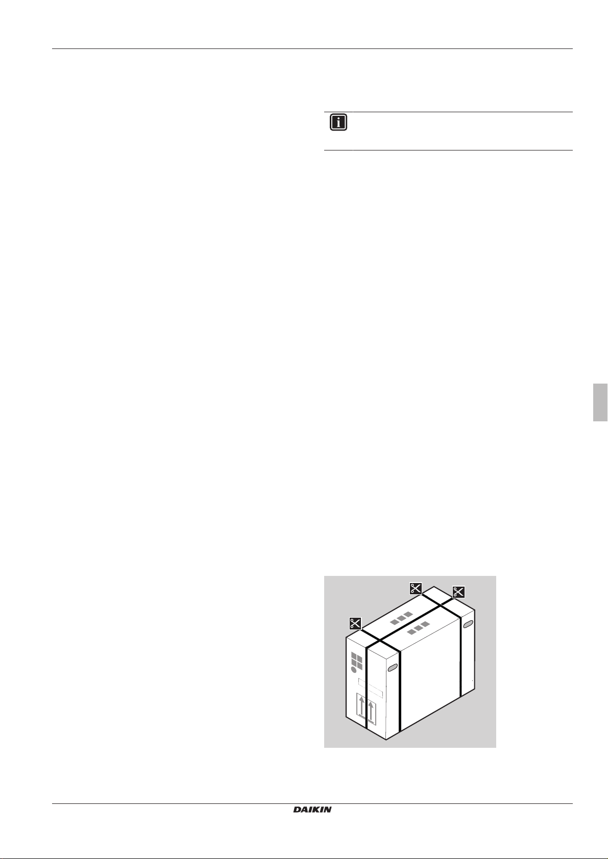
Table of contents
Table of contents
1 About the documentation 3
1.1 About this document.................................................................. 3
2 About the box 3
2.1 Outdoor unit............................................................................... 3
2.1.1 To unpack the outdoor unit ......................................... 3
2.1.2 To remove the accessories from the outdoor unit....... 4
3 Preparation 4
3.1 Preparing the installation site .................................................... 4
3.1.1 Installation site requirements of the outdoor unit ........ 4
3.1.2 Additional installation site requirements of the
outdoor unit in cold climates ....................................... 4
3.2 Preparing refrigerant piping....................................................... 5
3.2.1 Refrigerant piping requirements.................................. 5
3.2.2 Refrigerant piping length and height difference .......... 5
3.2.3 Refrigerant piping insulation ....................................... 5
4 Installation 5
4.1 Opening the units ...................................................................... 5
4.1.1 To open the outdoor unit............................................. 5
4.2 Mounting the outdoor unit.......................................................... 5
4.2.1 To provide the installation structure............................ 5
4.2.2 To install the outdoor unit............................................ 6
4.2.3 To provide drainage.................................................... 6
4.2.4 To prevent the outdoor unit from falling over .............. 6
4.3 Connecting the refrigerant piping .............................................. 6
4.3.1 About connecting the refrigerant piping ...................... 6
4.3.2 Precautions when connecting the refrigerant piping... 7
4.3.3 To connect the refrigerant piping to the outdoor unit .. 7
4.4 Checking the refrigerant piping ................................................. 7
4.4.1 To check for leaks....................................................... 7
4.4.2 To perform vacuum drying.......................................... 7
4.5 Charging refrigerant .................................................................. 7
4.5.1 About charging refrigerant .......................................... 7
4.5.2 About the refrigerant ................................................... 8
4.5.3 To determine the additional refrigerant amount.......... 8
4.5.4 To determine the complete recharge amount............. 8
4.5.5 To charge additional refrigerant.................................. 8
4.5.6 To fix the fluorinated greenhouse gases label ............ 9
4.6 Connecting the electrical wiring................................................. 9
4.6.1 Specifications of standard wiring components............ 9
4.6.2 To connect the electrical wiring on the outdoor unit.... 9
4.7 Finishing the outdoor unit installation ........................................ 10
4.7.1 To finish the outdoor unit installation .......................... 10
4.7.2 To close the outdoor unit ............................................ 10
1 About the documentation
1.1 About this document
INFORMATION
Make sure that the user has the printed documentation and
ask him/her to keep it for future reference.
Target audience
Authorised installers
Documentation set
This document is part of a documentation set. The complete set
consists of:
▪ General safety precautions:
▪ Safety instructions that you MUST read before installing
▪ Format: Paper (in the box of the outdoor unit)
▪ Outdoor unit installation manual:
▪ Installation instructions
▪ Format: Paper (in the box of the outdoor unit)
▪ Installer reference guide:
▪ Preparation of the installation, reference data,…
▪ Format: Digital files on http://www.daikineurope.com/support-
and-manuals/product-information/
Latest revisions of the supplied documentation may be available on
the regional Daikin website or via your dealer.
The original documentation is written in English. All other languages
are translations.
Technical engineering data
▪ A subset of the latest technical data is available on the regional
Daikin website (publicly accessible).
▪ The full set of latest technical data is available on the Daikin
extranet (authentication required).
2 About the box
2.1 Outdoor unit
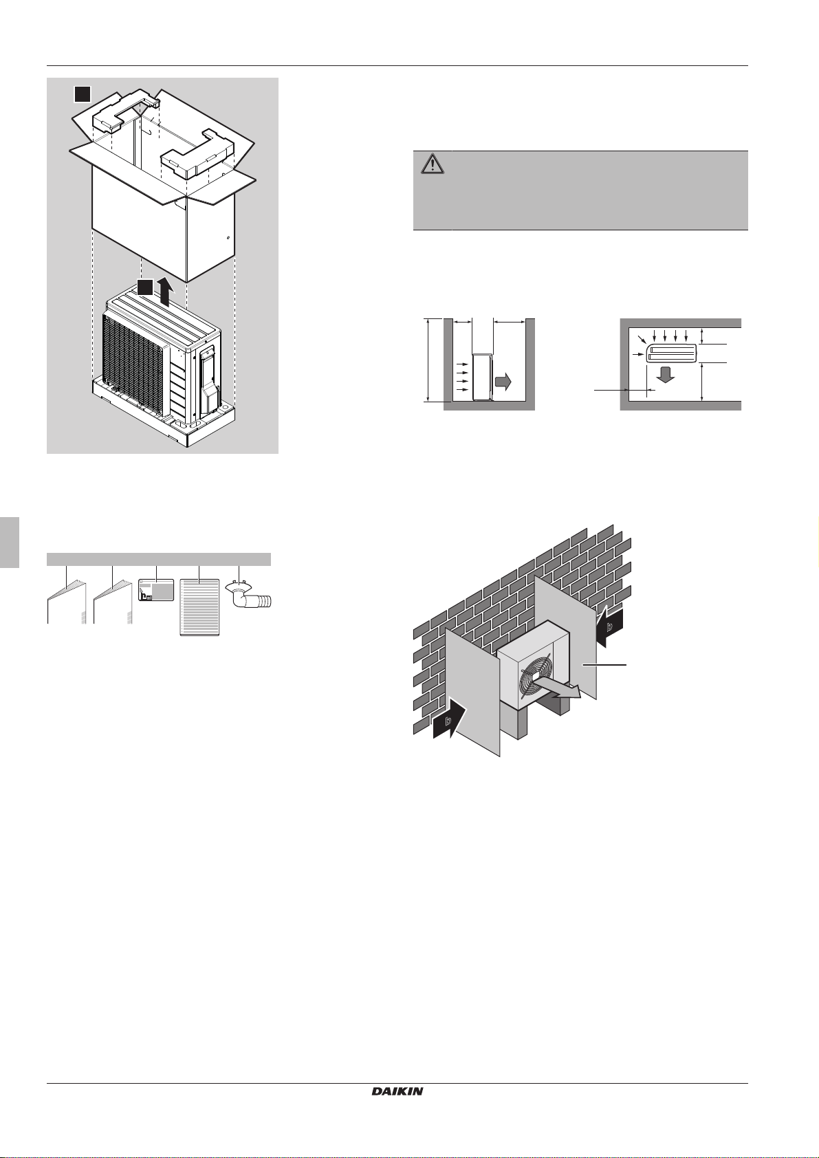
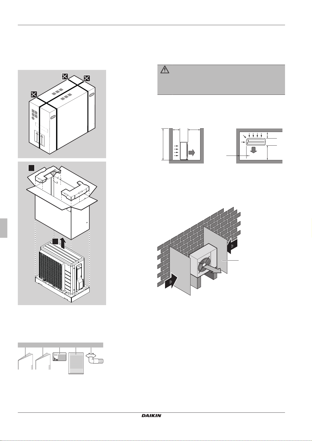
2.1.1 To unpack the outdoor unit
5 Commissioning 10
5.1 Checklist before commissioning................................................ 10
5.2 Checklist during commissioning ................................................ 10
5.3 To perform a test run................................................................. 10
5.4 Starting up the outdoor unit ....................................................... 10
6 Disposal 11
6.1 Overview: Disposal.................................................................... 11
6.2 To pump down........................................................................... 11
6.3 To start and stop forced cooling ................................................ 11
6.3.1 To start/stop forced cooling using the indoor unit ON/
OFF switch.................................................................. 11
6.3.2 To start/stop forced cooling using the indoor unit
user interface .............................................................. 11
7 Technical data 12
7.1 Wiring diagram .......................................................................... 12
(A)RXP20~35M5V1B
R32 split series
3P519299-5B – 2018.12
Installation manual
3
3 Preparation
1
2
b ec d
1×
a
1× 1× 1× 1×
≤1200
>150
>150
>50
>300
>300
(mm)(mm)
a
b
b
a
b
a
b
c
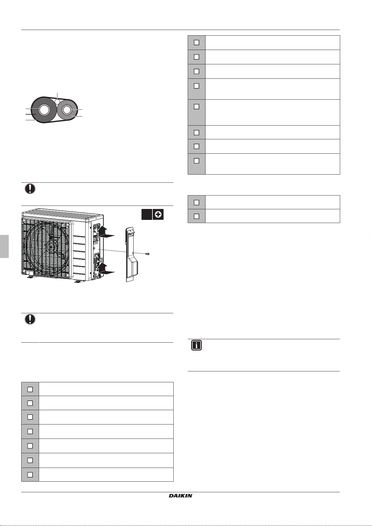
2.1.2 To remove the accessories from the outdoor unit
1 Lift the outdoor unit.
2 Remove the accessories at the bottom of the package.
3 Preparation
3.1 Preparing the installation site
WARNING
The appliance shall be stored in a room without
continuously operating ignition sources (example: open
flames, an operating gas appliance or an operating electric
heater).
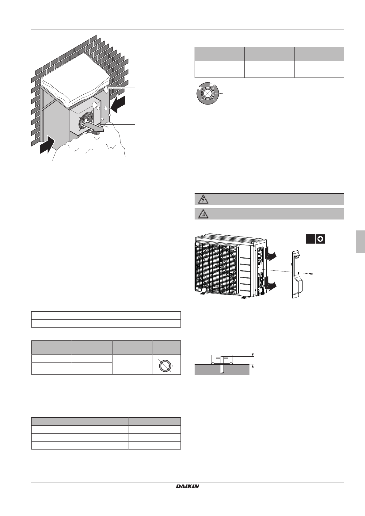
3.1.1 Installation site requirements of the outdoor unit
Mind the following spacing guidelines:
a Air outlet
b Air inlet
It is recommended to install a baffle plate when the air outlet is
exposed to wind.
It is recommended to install the outdoor unit with the air inlet facing
the wall and NOT directly exposed to the wind.
a General safety precautions
b Outdoor unit installation manual
c Fluorinated greenhouse gases label
d Multilingual fluorinated greenhouse gases label
e Drain plug (located on the bottom of the packing case)
Installation manual
4
a Baffle plate
b Prevailing wind direction
c Air outlet
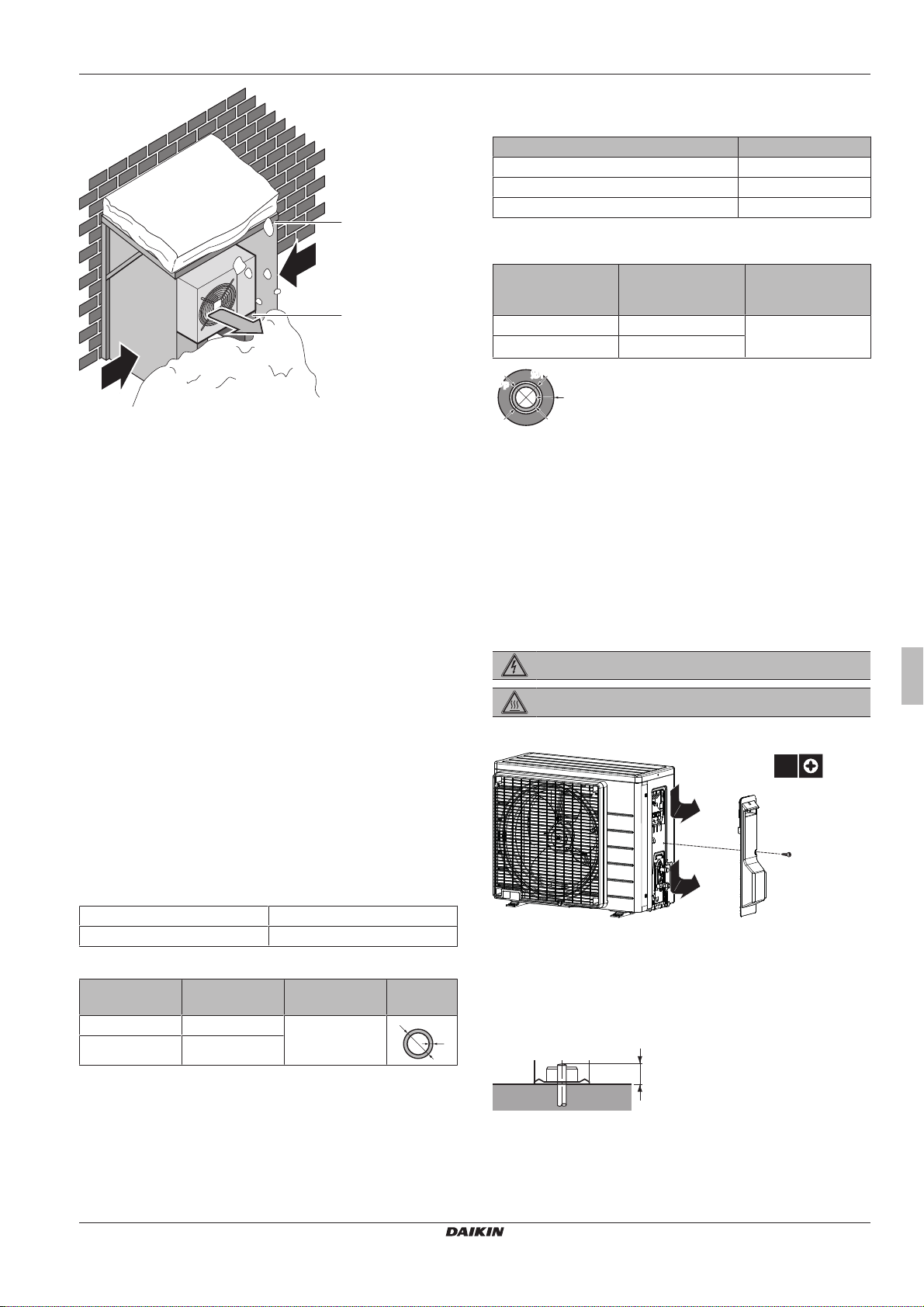
3.1.2 Additional installation site requirements of the outdoor unit in cold climates
Protect the outdoor unit against direct snowfall and take care that the
outdoor unit is NEVER snowed up.
(A)RXP20~35M5V1B
R32 split series
3P519299-5B – 2018.12
a
b
c
c
d
t
Ø
3.2.3 Refrigerant piping insulation
ØiØ
i
t
ØpØ
p
1×
2
1
2
20 mm
4 Installation
a Snow cover or shed
b Pedestal
c Prevailing wind direction
d Air outlet
In any case, provide at least 300mm of free space below the unit.
Additionally, make sure the unit is positioned at least 100mm above
the maximum expected level of snow. See "4.2 Mounting the
outdoor unit"on page5 for more details.
In heavy snowfall areas it is very important to select an installation
site where the snow will NOT affect the unit. If lateral snowfall is
possible, make sure that the heat exchanger coil is NOT affected by
the snow. If necessary, install a snow cover or shed and a pedestal.
Pipe outer diameter
(Øp)
6.4mm (1/4") 8~10mm ≥10mm
9.5mm (3/8") 12~15mm
If the temperature is higher than 30°C and the humidity is higher
than RH 80%, the thickness of the insulation materials should be at
least 20 mm to prevent condensation on the surface of the
insulation.
Insulation inner
diameter (Øi)
Insulation thickness
(t)
4 Installation
4.1 Opening the units
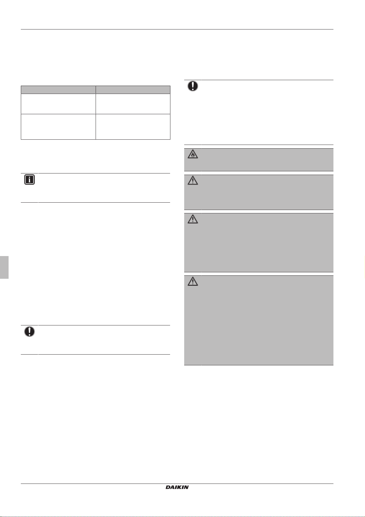
4.1.1 To open the outdoor unit
DANGER: RISK OF ELECTROCUTION
DANGER: RISK OF BURNING
See also
2 4.2 Mounting the outdoor unit [}5]
3.2 Preparing refrigerant piping
3.2.1 Refrigerant piping requirements
▪ Piping material: Phosphoric acid deoxidised seamless copper.
▪ Piping diameter:
Liquid piping Ø6.4mm (1/4")
Gas piping Ø9.5mm (3/8")
▪ Piping temper grade and thickness:
Outer diameter
(Ø)
6.4mm (1/4") Annealed (O) ≥0.8mm
9.5mm (3/8") Annealed (O)
(a) Depending on the applicable legislation and the unit's
Temper grade Thickness (t)
maximum working pressure (see "PS High" on the unit
name plate), larger piping thickness might be required.
3.2.2 Refrigerant piping length and height difference
What? Distance
Maximum allowable pipe length 15m
Minimum allowable pipe length 1.5m
Maximum allowable height difference 12m
(a)
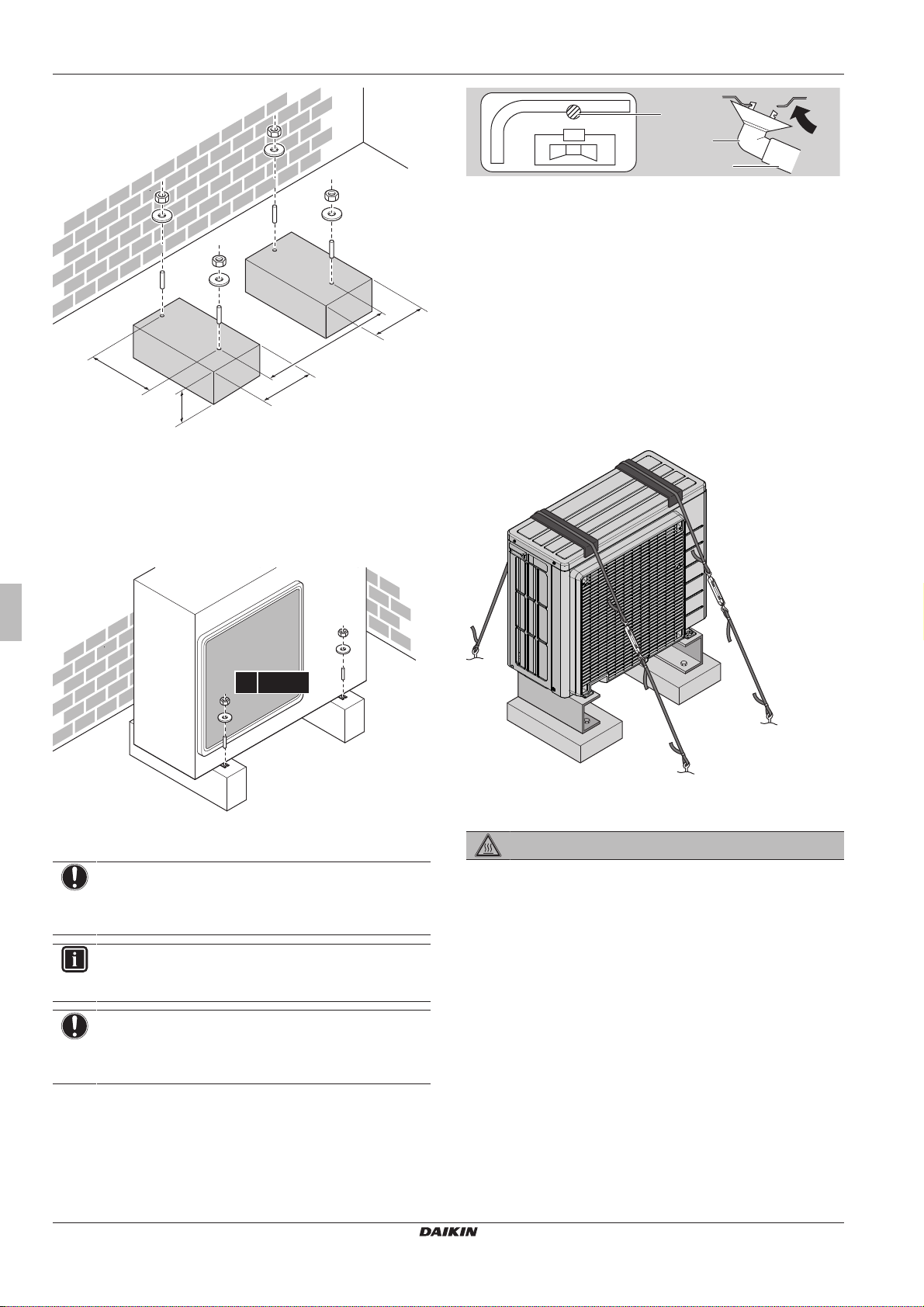
4.2 Mounting the outdoor unit
4.2.1 To provide the installation structure
Prepare 4 sets of M8 or M10 anchor bolts, nuts and washers (field
supply).
(A)RXP20~35M5V1B
R32 split series
3P519299-5B – 2018.12
Installation manual
5
4 Installation
300
470
192
(mm)
192
>300
4× M8/M10
b
c
d
a
In any case, provide at least 300mm of free space below the unit.
Additionally, make sure the unit is positioned at least 100mm above
the maximum expected level of snow. In this case, it is
recommended to construct a pedestal.
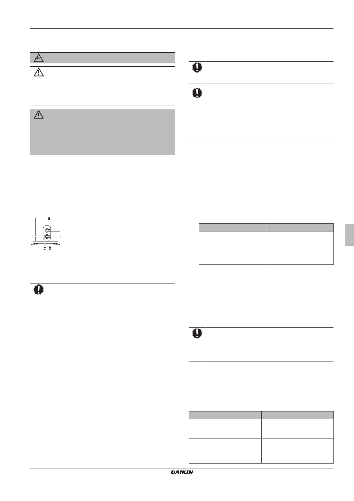
a Drain port
b Bottom frame
c Drain plug
d Hose (field supply)
4.2.4 To prevent the outdoor unit from falling over
In case the unit is installed in places where strong wind can tilt the
unit, take following measure:
1 Prepare 2 cables as indicated in the following illustration (field
supply).
2 Place the 2 cables over the outdoor unit.
3 Insert a rubber sheet between the cables and the outdoor unit
to prevent the cables from scratching the paint (field supply).
4 Attach the ends of the cables and tighten them.
4.2.2 To install the outdoor unit
4.2.3 To provide drainage
NOTICE
If the unit is installed in a cold climate, take adequate
measures so that the evacuated condensate CANNOT
freeze.
INFORMATION
For information on the available options, contact your
dealer.
NOTICE
Provide at least 300 mm of free space below the unit.
Additionally, make sure the unit is positioned at least
100mm above the expected level of snow.
1 Use a drain plug for drainage.
2 Use a Ø16mm hose (field supply).
4.3 Connecting the refrigerant piping
DANGER: RISK OF BURNING
4.3.1 About connecting the refrigerant piping
Before connecting the refrigerant piping
Make sure the outdoor and indoor unit are mounted.
Typical workflow
Connecting the refrigerant piping involves:
▪ Connecting the refrigerant piping to the indoor unit
▪ Connecting the refrigerant piping to the outdoor unit
▪ Insulating the refrigerant piping
▪ Keeping in mind the guidelines for:
▪ Pipe bending
▪ Flaring pipe ends
▪ Using the stop valves
Installation manual
6
(A)RXP20~35M5V1B
R32 split series
3P519299-5B – 2018.12
4 Installation
a
bc
4.3.2 Precautions when connecting the refrigerant piping
DANGER: RISK OF BURNING
CAUTION
▪ Use the flare nut fixed to the main unit.
▪ To prevent gas leakage, apply refrigeration oil only to
the inside of the flare. Use refrigeration oil for R32.
▪ Do NOT reuse joints.
WARNING
Connect the refrigerant piping securely before running the
compressor. If the refrigerant piping is NOT connected and
the stop valve is open when the compressor is run, air will
be sucked in. This will cause abnormal pressure in the
refrigeration cycle, which may result in equipment damage
and even injury.
4.3.3 To connect the refrigerant piping to the outdoor unit
▪ Piping length. Keep field piping as short as possible.
▪ Piping protection. Protect the field piping against physical
damage.
1 Connect the liquid refrigerant connection from the indoor unit to
the liquid stop valve of the outdoor unit.
4.4 Checking the refrigerant piping
4.4.1 To check for leaks
NOTICE
Do NOT exceed the unit's maximum working pressure (see
"PS High" on the unit name plate).
NOTICE
Make sure to use a recommended bubble test solution
from your wholesaler. Do not use soap water, which may
cause cracking of flare nuts (soap water may contain salt,
which absorbs moisture that will freeze when the piping
gets cold), and/or lead to corrosion of flared joints (soap
water may contain ammonia which causes a corrosive
effect between the brass flare nut and the copper flare).
1 Charge the system with nitrogen gas up to a gauge pressure of
at least 200kPa (2 bar). It is recommended to pressurize to
3000kPa (30bar) in order to detect small leaks.
2 Check for leaks by applying the bubble test solution to all
connections.
3 Discharge all nitrogen gas.
4.4.2 To perform vacuum drying
1 Vacuum the system until the pressure on the manifold indicates
−0.1MPa (−1bar).
2 Leave as is for 4-5minutes and check the pressure:
a Liquid stop valve
b Gas stop valve
c Service port
2 Connect the gas refrigerant connection from the indoor unit to
the gas stop valve of the outdoor unit.
NOTICE
It is recommended that the refrigerant piping between
indoor and outdoor unit is installed in a ducting or the
refrigerant piping is wrapped with finishing tape.
If the pressure… Then…
Does not change There is no moisture in the
system. This procedure is
finished.
Increases There is moisture in the
system. Go to the next step.
3 Vacuum the system for at least 2hours to a manifold pressure
of −0.1MPa (−1bar).
4 After turning the pump OFF, check the pressure for at least
1hour.
5 If you do NOT reach the target vacuum or CANNOT maintain
the vacuum for 1hour, do the following:
▪ Check for leaks again.
▪ Perform vacuum drying again.
NOTICE
Make sure to open the stop valves after installing the
refrigerant piping and performing vacuum drying. Running
the system with the stop valves closed may break the
compressor.
4.5 Charging refrigerant
4.5.1 About charging refrigerant
The outdoor unit is factory charged with refrigerant, but in some
cases the following might be necessary:
(A)RXP20~35M5V1B
R32 split series
3P519299-5B – 2018.12
What When
Charging additional refrigerant When the total liquid piping
length is more than specified
(see later).
Completely recharging refrigerant Example:
▪ When relocating the system.
▪ After a leak.
Installation manual
7
4 Installation
Charging additional refrigerant
Before charging additional refrigerant, make sure the outdoor unit's
external refrigerant piping is checked (leak test, vacuum drying).
INFORMATION
Depending on the units and/or the installation conditions, it
might be necessary to connect electrical wiring before you
can charge refrigerant.
Typical workflow – Charging additional refrigerant typically consists
of the following stages:
1 Determining if and how much you have to charge additionally.
2 If necessary, charging additional refrigerant.
3 Filling in the fluorinated greenhouse gases label, and fixing it to
the inside of the outdoor unit.
Completely recharging refrigerant
Before completely recharging refrigerant, make sure the following is
done:
1 All refrigerant is recovered from the system.
2 The outdoor unit's external refrigerant piping is checked (leak
test, vacuum drying).
3 Vacuum drying on the outdoor unit's internal refrigerant piping is
performed.
NOTICE
Before completely recharging, perform vacuum drying on
the outdoor unit's internal refrigerant piping as well.
Typical workflow – Completely recharging refrigerant typically
consists of the following stages:
1 Determining how much refrigerant to charge.
2 Charging refrigerant.
3 Filling in the fluorinated greenhouse gases label, and fixing it to
the inside of the outdoor unit.
4.5.2 About the refrigerant
This product contains fluorinated greenhouse gases. Do NOT vent
gases into the atmosphere.
Refrigerant type: R32
Global warming potential (GWP) value: 675
NOTICE
In Europe, the greenhouse gas emissions of the total
refrigerant charge in the system (expressed as tonnes CO
equivalent) is used to determine the maintenance intervals.
Follow the applicable legislation.
Formula to calculate the greenhouse gas emissions:
GWP value of the refrigerant × Total refrigerant charge [in
kg] / 1000
Please contact your installer for more information.
WARNING: FLAMMABLE MATERIAL
The refrigerant inside this unit is mildly flammable.
WARNING
The appliance shall be stored in a room without
continuously operating ignition sources (example: open
flames, an operating gas appliance or an operating electric
heater).
WARNING
▪ Do NOT pierce or burn refrigerant cycle parts.
▪ Do NOT use cleaning materials or means to accelerate
the defrosting process other than those recommended
by the manufacturer.
▪ Be aware that the refrigerant inside the system is
odourless.
WARNING
The refrigerant inside the unit is mildly flammable, but
normally does NOT leak. If the refrigerant leaks in the
room and comes in contact with fire from a burner, a
heater, or a cooker, this may result in fire, or the formation
of a harmful gas.
Turn off any combustible heating devices, ventilate the
room, and contact the dealer where you purchased the
unit.
Do NOT use the unit until a service person confirms that
the part from which the refrigerant leaked has been
repaired.
4.5.3 To determine the additional refrigerant amount
If the total liquid
piping length is…
≤10m Do NOT add additional refrigerant.
>10m R=(total length (m) of liquid
piping–10m)×0.020
R=Additional charge (kg) (rounded in units
of 0.01kg)
INFORMATION
Piping length is the one-way length of liquid piping.
Then…
4.5.4 To determine the complete recharge amount
INFORMATION
If a complete recharge is necessary, the total refrigerant
charge is: the factory refrigerant charge (see unit name
plate) + the determined additional amount.
4.5.5 To charge additional refrigerant
2
WARNING
▪ Only use R32 as refrigerant. Other substances may
cause explosions and accidents.
▪ R32 contains fluorinated greenhouse gases. Its global
warming potential (GWP) value is 675. Do NOT vent
these gases into the atmosphere.
▪ When charging refrigerant, ALWAYS use protective
gloves and safety glasses.
Prerequisite: Before charging refrigerant, make sure the refrigerant
piping is connected and checked (leak test and vacuum drying).
1 Connect the refrigerant cylinder to the service port.
2 Charge the additional refrigerant amount.
3 Open the gas stop valve.
Installation manual
8
(A)RXP20~35M5V1B
R32 split series
3P519299-5B – 2018.12
4 Installation
b
Contains fluorinated greenhouse gases
2
1
1
1
2
2
kg
tCO2eq
GWP × kg
1000
=
=
+
kg
=
kg
=
GWP: XXX
RXXX
a
f
c
d
e
50 Hz
220-240 V
c d
f
a b e
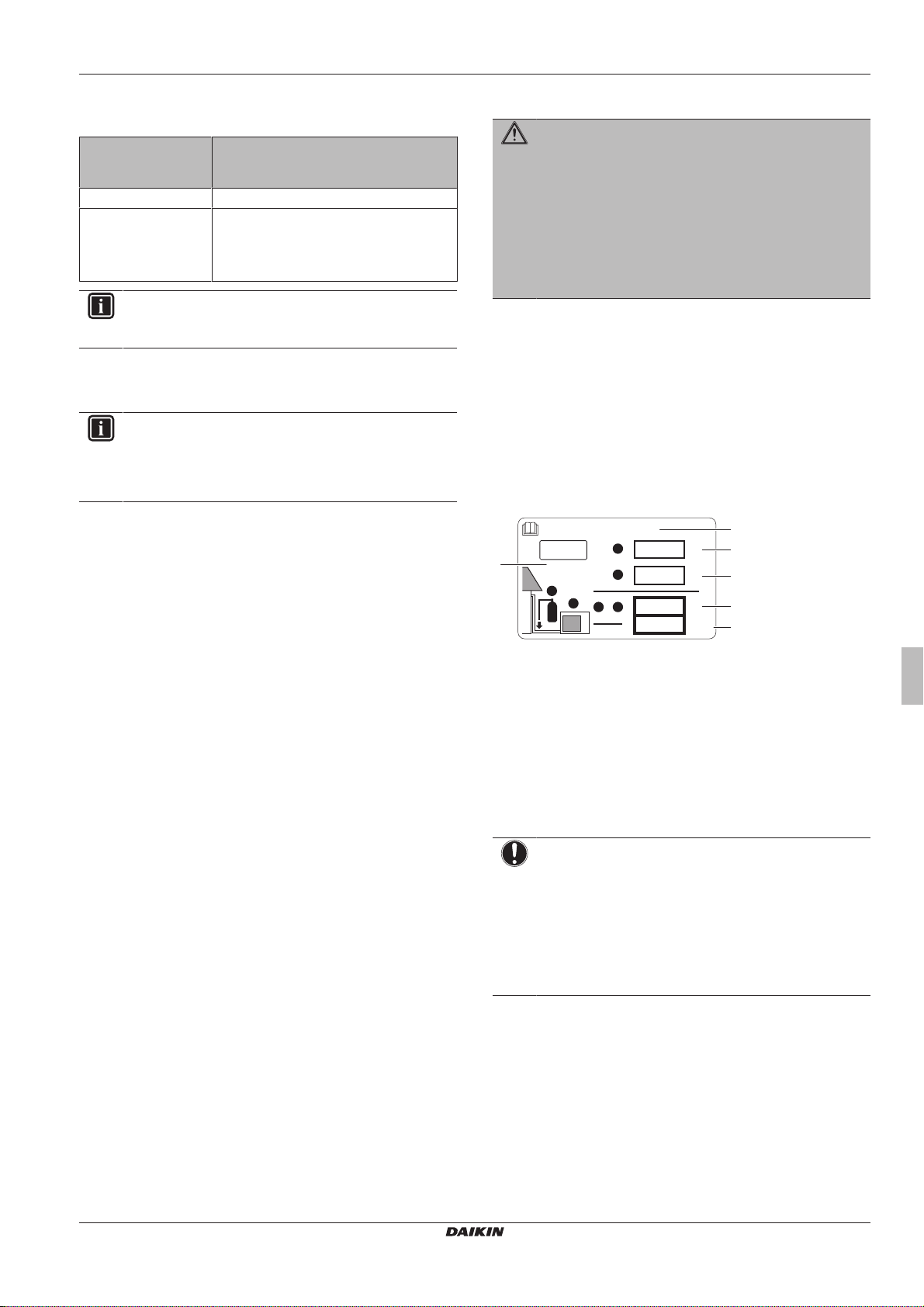
4.5.6 To fix the fluorinated greenhouse gases label
1 Fill in the label as follows:
a If a multilingual fluorinated greenhouse gases label is
delivered with the unit (see accessories), peel off the
applicable language and stick it on top of a.
b Factory refrigerant charge: see unit name plate
c Additional refrigerant amount charged
d Total refrigerant charge
e Greenhouse gas emissions of the total refrigerant charge
expressed as tonnes CO2 equivalent
f GWP = Global warming potential
NOTICE
In Europe, the greenhouse gas emissions of the total
refrigerant charge in the system (expressed as tonnes CO
equivalent) is used to determine the maintenance intervals.
Follow the applicable legislation.
Formula to calculate the greenhouse gas emissions:
GWP value of the refrigerant × Total refrigerant charge [in
kg] / 1000
2 Fix the label on the inside of the outdoor unit near the gas and
liquid stop valves.
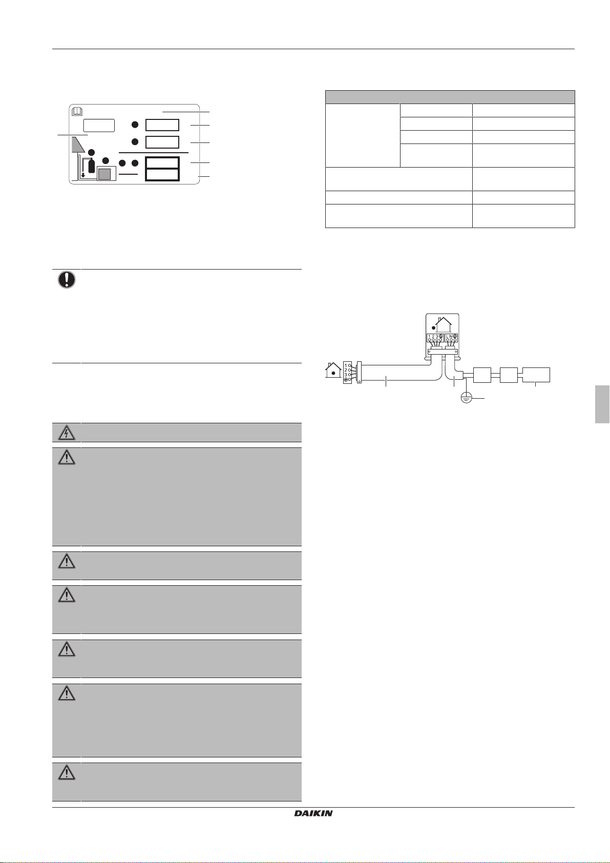
4.6.1 Specifications of standard wiring components
Component
Power supply cable Voltage 220~240V
Phase 1~
Frequency 50Hz
Wire sizes MUST comply with
Interconnection cable
(indoor↔outdoor)
4-core cable ≥1.5 mm² and
applicable for 220~240 V
Recommended field fuse 16A
Earth leakage circuit breaker MUST comply with
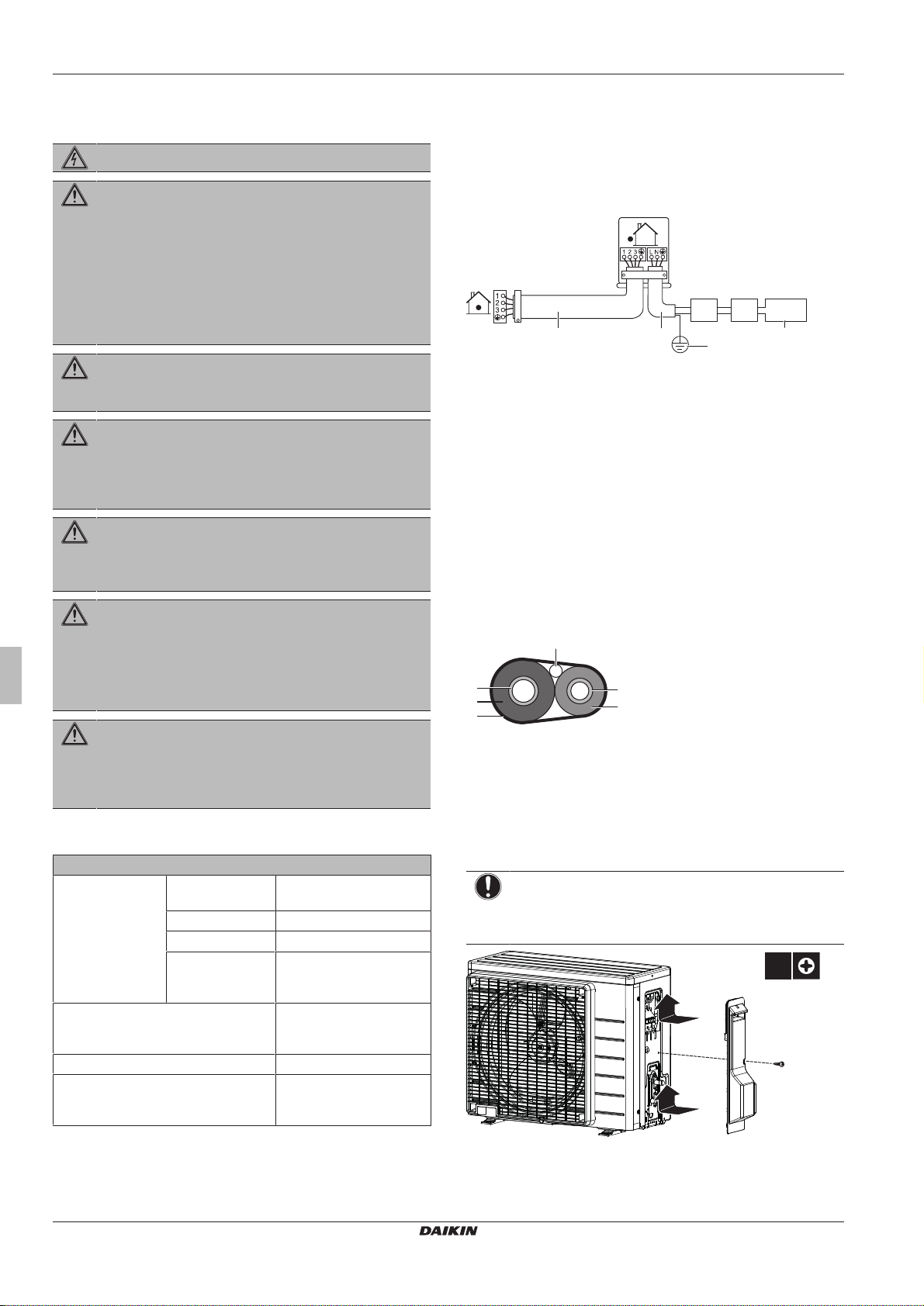
4.6.2 To connect the electrical wiring on the outdoor unit
1 Remove the service cover.
2 Open the wire clamp.
2
3 Connect the interconnection cable and power supply as follows:
applicable legislation
applicable legislation
4.6 Connecting the electrical wiring
DANGER: RISK OF ELECTROCUTION
WARNING
▪ All wiring MUST be performed by an authorised
electrician and MUST comply with the applicable
legislation.
▪ Make electrical connections to the fixed wiring.
▪ All components procured on-site and all electrical
construction MUST comply with the applicable
legislation.
WARNING
ALWAYS use multicore cable for power supply cables.
WARNING
If the supply cord is damaged, it MUST be replaced by the
manufacturer, its service agent or similarly qualified
persons in order to avoid a hazard.
WARNING
Do NOT connect the power supply to the indoor unit. This
could result in electrical shock or fire.
WARNING
▪ Do NOT use locally purchased electrical parts inside
the product.
▪ Do NOT branch the power supply for the drain pump,
etc. from the terminal block. This could result in
electrical shock or fire.
a Interconnection cable
b Power supply cable
c Circuit breaker
d Earth leakage circuit breaker
e Power supply
f Earth
4 Tighten the terminal screws securely. We recommend using a
Phillips screwdriver.
WARNING
(A)RXP20~35M5V1B
R32 split series
3P519299-5B – 2018.12
Keep the interconnection wiring away from copper pipes
without thermal insulation as such pipes will be very hot.
Installation manual
9
5 Commissioning
f
b
a
e
d
c
1×
2
1
1
4.7 Finishing the outdoor unit installation
4.7.1 To finish the outdoor unit installation
1 Insulate and fix the refrigerant piping and interconnection cable
as follows:
a Gas pipe
b Gas pipe insulation
c Interconnection cable
d Liquid pipe
e Liquid pipe insulation
f Finishing tape
2 Install the service cover.
4.7.2 To close the outdoor unit
NOTICE
When closing the outdoor unit cover, make sure that the
tightening torque does NOT exceed 1.3N•m.
The refrigerant pipes (gas and liquid) are thermally
insulated.
The correct pipe size is installed and the pipes are
properly insulated.
The stop valves (gas and liquid) on the outdoor unit are
fully open.
The following field wiring has been carried out according
to this document and the applicable legislation between
the outdoor unit and the indoor unit.
Drainage
Make sure drainage flows smoothly.
Possible consequence: Condensate water might drip.
The indoor unit receives the signals of the user interface.
The specified wires are used for the interconnection
cable.
The fuses, circuit breakers, or locally installed protection
devices are installed according to this document, and
have NOT been bypassed.
5.2 Checklist during commissioning
To perform an air purge.
To perform a test run.
5 Commissioning
NOTICE
NEVER operate the unit without thermistors and/or
pressure sensors/switches. Burning of the compressor
might result.
5.1 Checklist before commissioning
After the installation of the unit, first check the following items. Once
all below checks are fulfilled, the unit MUST be closed, ONLY then
can the unit be powered up.
The indoor unit is properly mounted.
The outdoor unit is properly mounted.
The system is properly earthed and the earth terminals
are tightened.
The power supply voltage matches the voltage on the
identification label of the unit.
There are NO loose connections or damaged electrical
components in the switchbox.
There are NO damaged components or squeezed
pipes on the inside of the indoor and outdoor units.
There are NO refrigerant leaks.
5.3 To perform a test run
Prerequisite: Power supply MUST be in the specified range.
Prerequisite: Test run may be performed in cooling or heating
mode.
Prerequisite: Test run should be performed in accordance with the
operation manual of the indoor unit to make sure that all functions
and parts are working properly.
1 In cooling mode, select the lowest programmable temperature.
In heating mode, select the highest programmable temperature.
Test run can be disabled if necessary.
2 When the test run is finished, set the temperature to a normal
level. In cooling mode: 26~28°C, in heating mode: 20~24°C.
3 The system stops operating 3 minutes after the unit is turned
OFF.
INFORMATION
▪ Even if the unit is turned OFF, it consumes electricity.
▪ When the power turns back on after a power break, the
previously selected mode will be resumed.
5.4 Starting up the outdoor unit
See the indoor unit installation manual for configuration and
commissioning of the system.
Installation manual
10
(A)RXP20~35M5V1B
R32 split series
3P519299-5B – 2018.12
6 Disposal
c
b
e
d
d
a
6 Disposal
NOTICE
Do NOT try to dismantle the system yourself: dismantling
of the system, treatment of the refrigerant, oil and other
parts MUST comply with applicable legislation. Units
MUST be treated at a specialised treatment facility for
reuse, recycling and recovery.
6.1 Overview: Disposal
Typical workflow
Disposing of the system typically consists of the following stages:
1 Pumping down the system.
2 Bringing the system to a specialized treatment facility.
INFORMATION
For more details, see the service manual.
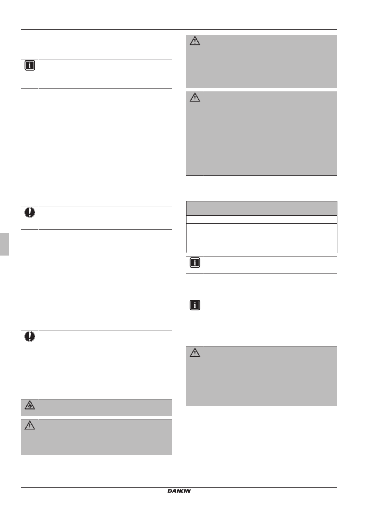
6.2 To pump down
DANGER: RISK OF EXPLOSION
Pump down – Refrigerant leakage. If you want to pump
down the system, and there is a leak in the refrigerant
circuit:
▪ Do NOT use the unit's automatic pump down function,
with which you can collect all refrigerant from the
system into the outdoor unit. Possible consequence:
Self-combustion and explosion of the compressor
because of air going into the operating compressor.
▪ Use a separate recovery system so that the unit's
compressor does NOT have to operate.
6.3 To start and stop forced cooling
There are 2methods to perform forced cooling.
▪ Method 1. Using the indoor unit ON/OFF switch (if present on the
indoor unit).
▪ Method 2. Using the indoor unit user interface.
6.3.1 To start/stop forced cooling using the indoor unit ON/OFF switch
1 Press the ON/OFF switch for at least 5seconds.
Result: Operation will start.
INFORMATION
Forced cooling stops automatically after 15minutes.
2 To stop operation sooner, press the ON/OFF switch.
6.3.2 To start/stop forced cooling using the indoor unit user interface
1 Set the operation mode to cooling.
For the procedure, refer to "To perform a test run" in the installation
manual of the indoor unit.
NOTICE
During pump down operation, stop the compressor before
removing the refrigerant piping. If the compressor is still
running and the stop valve is open during pump down, air
will be sucked into the system. Compressor breakdown or
damage to the system can result due to abnormal pressure
in the refrigerant cycle.
Pump down operation will extract all refrigerant from the system into
the outdoor unit.
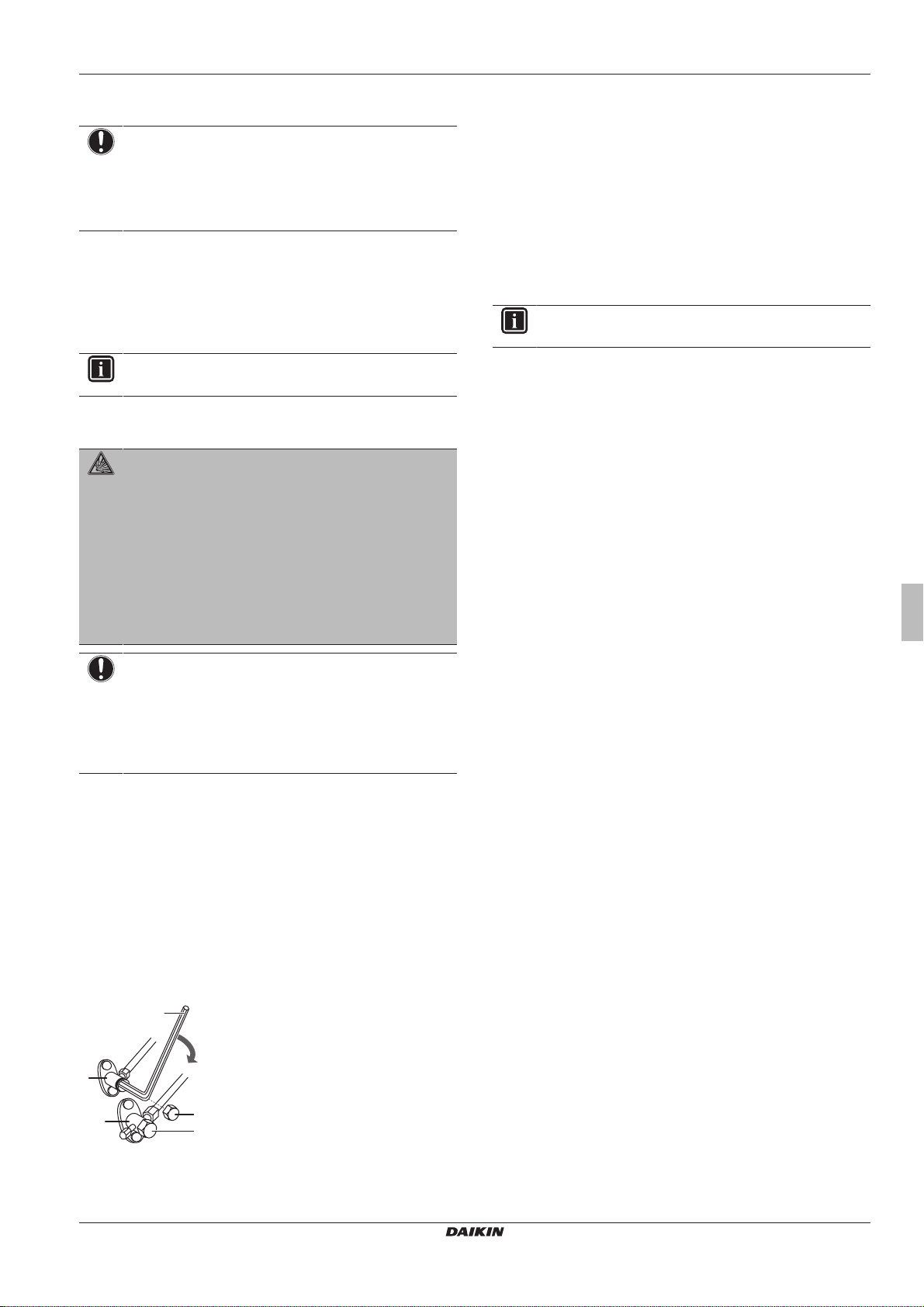
1 Remove the valve cap from the liquid stop valve and the gas
stop valve.
2 Carry out forced cooling. See "6.3 To start and stop forced
cooling"on page11.
3 After 5 to 10 minutes (after only 1 or 2 minutes in case of very
low ambient temperatures (<−10°C)), close the liquid stop valve
with a hexagonal wrench.
4 Check on the manifold if the vacuum is reached.
5 After 2-3 minutes, close the gas stop valve and stop forced
cooling.
a Gas stop valve
(A)RXP20~35M5V1B
R32 split series
3P519299-5B – 2018.12
b Closing direction
c Hexagonal wrench
d Valve cap
e Liquid stop valve
Installation manual
11

7 Technical data
,
A
INDOOR
OUTDOOR
For applied parts and numbering, refer to the wiring diagram on the unit. Part numbering is by Arabic numbers in ascending order for each part
and is represented in the overview below by symbol “*” in the part code.
Unified Wiring Diagram Legend
: CIRCUIT BREAKER
: CONNECTION
: CONNECTOR
: EARTH
: FIELD WIRING
: FUSE
: INDOOR UNIT
: OUTDOOR UNIT
: PROTECTIVE EARTH
: PROTECTIVE EARTH (SCREW)
: RECTIFIER
: RELAY CONNECTOR
: SHORT-CIRCUIT CONNECTOR
: TERMINAL
: TERMINAL STRIP
: WIRE CLAMP
WHT : WHITE
YLW : YELLOW
PNK : PINK
PRP, PPL : PURPLE
RED : RED
GRN : GREEN
GRY : GREY
ORG : ORANGE
BLK : BLACK
BLU : BLUE
BRN : BROWN
A*P : PRINTED CIRCUIT BOARD
BS* : PUSHBUTTON ON/OFF, OPERATION SWITCH
BZ, H*O : BUZZER
C* : CAPACITOR
AC*, CN*, E*, HA*, HE*, HL*, HN*, : CONNECTION, CONNECTOR
HR*, MR*_A, MR*_B, S*, U, V,
W, X*A, K*R_*
D*, V*D : DIODE
DB* : DIODE BRIDGE
DS* : DIP SWITCH
E*H : HEATER
F*U, FU*
(FOR CHARACTERISTICS,
: FUSE
REFER TO PCB INSIDE YOUR UNIT)
FG* : CONNECTOR (FRAME GROUND)
H* : HARNESS
H*P, LED*, V*L : PILOT LAMP, LIGHT EMITTING DIODE
HAP : LIGHT EMITTING DIODE (SERVICE MONITOR GREEN)
HIGH VOLTAGE : HIGH VOLTAGE
IES : INTELLIGENT EYE SENSOR
IPM* : INTELLIGENT POWER MODULE
K*R, KCR, KFR, KHuR, K*M : MAGNETIC RELAY
L : LIVE
L* : COIL
L*R : REACTOR
M* : STEPPER MOTOR
M*C : COMPRESSOR MOTOR
M*F : FAN MOTOR
M*P : DRAIN PUMP MOTOR
M*S : SWING MOTOR
MR*, MRCW*, MRM*, MRN* : MAGNETIC RELAY
N : NEUTRAL
n=*, N=* : NUMBER OF PASSES THROUGH FERRITE CORE
PAM : PULSE-AMPLITUDE MODULATION
PCB* : PRINTED CIRCUIT BOARD
PM* : POWER MODULE
PS : SWITCHING POWER SUPPLY
PTC* : THERMISTOR PTC
Q* : INSULATED GATE BIPOLAR TRANSISTOR
(IGBT)
Q*DI : EARTH LEAK CIRCUIT BREAKER
Q*L : OVERLOAD PROTECTOR
Q*M : THERMO SWITCH
R* : RESISTOR
R*T : THERMISTOR
RC : RECEIVER
S*C : LIMIT SWITCH
S*L : FLOAT SWITCH
S*NPH : PRESSURE SENSOR (HIGH)
S*NPL : PRESSURE SENSOR (LOW)
S*PH, HPS* : PRESSURE SWITCH (HIGH)
S*PL : PRESSURE SWITCH (LOW)
S*T : THERMOSTAT
S*RH : HUMIDITY SENSOR
S*W, SW* : OPERATION SWITCH
SA*, F1S : SURGE ARRESTOR
SR*, WLU : SIGNAL RECEIVER
SS* : SELECTOR SWITCH
SHEET METAL : TERMINAL STRIP FIXED PLATE
T*R : TRANSFORMER
TC, TRC : TRANSMITTER
V*, R*V : VARISTOR
V*R : DIODE BRIDGE
WRC : WIRELESS REMOTE CONTROLLER
X* : TERMINAL
X*M : TERMINAL STRIP (BLOCK)
Y*E : ELECTRONIC EXPANSION VALVE COIL
Y*R, Y*S : REVERSING SOLENOID VALVE COIL
Z*C : FERRITE CORE
ZF, Z*F : NOISE FILTER
7 Technical data
A subset of the latest technical data is available on the regional Daikin website (publicly accessible). The full set of latest technical data is
available on the Daikin Business Portal (authentication required).
7.1 Wiring diagram
Installation manual
12
(A)RXP20~35M5V1B
R32 split series
3P519299-5B – 2018.12

Inhaltsverzeichnis
Inhaltsverzeichnis
1 Über die Dokumentation 13
1.1 Informationen zu diesem Dokument.......................................... 13
2 Über die Verpackung 14
2.1 Außengerät................................................................................ 14
2.1.1 So packen Sie das Außengerät aus ........................... 14
2.1.2 So entfernen Sie das Zubehör vom Außengerät ........ 14
3 Vorbereitung 14
3.1 Den Ort der Installation vorbereiten .......................................... 14
3.1.1 Anforderungen an den Installationsort für die
Außeneinheit............................................................... 14
3.1.2 Zusätzliche Anforderungen an den Installationsort für
die Außeneinheit bei kaltem Klima.............................. 14
3.2 Vorbereiten der Kältemittelleitungen ......................................... 15
3.2.1 Anforderungen an die Kältemittelleitungen................. 15
3.2.2 Länge der Kältemittelleitung und Höhenunterschied .. 15
3.2.3 Isolieren der Kältemittelleitungen................................ 15
4 Installation 15
4.1 Geräte öffnen ............................................................................ 15
4.1.1 So öffnen Sie das Außengerät.................................... 15
4.2 Montieren des Außengeräts ...................................................... 15
4.2.1 Voraussetzungen für die Installation........................... 15
4.2.2 So installieren Sie die Außeneinheit ........................... 16
4.2.3 Für einen Ablauf sorgen.............................................. 16
4.2.4 So vermeiden Sie ein Kippen des Außengeräts ......... 16
4.3 Anschließen der Kältemittelleitung ............................................ 16
4.3.1 Kältemitteilleitungen anschließen ............................... 16
4.3.2 Sicherheitsvorkehrungen beim Anschluss von
Kältemittelleitungen..................................................... 17
4.3.3 So schließen Sie Kältemittelrohre an die
Außeneinheit an.......................................................... 17
4.4 Überprüfen der Kältemittelleitung.............................................. 17
4.4.1 So führen Sie eine Leckprüfung durch........................ 17
4.4.2 So führen Sie die Vakuumtrocknung durch ................ 17
4.5 Einfüllen des Kältemittels .......................................................... 18
4.5.1 Informationen zum Einfüllen von Kältemittel............... 18
4.5.2 Über das Kältemittel.................................................... 18
4.5.3 So ermitteln Sie die nachzufüllende zusätzliche
Kältemittelmenge ........................................................ 19
4.5.4 Die Menge für eine komplette Neubefüllung
bestimmen .................................................................. 19
4.5.5 So füllen Sie zusätzliches Kältemittel ein.................... 19
4.5.6 So bringen Sie den Aufkleber mit Hinweisen zu
fluorierten Treibhausgasen an .................................... 19
4.6 Anschließen der elektrischen Leitungen ................................... 20
4.6.1 Spezifikationen der Standardelektroteile .................... 20
4.6.2 So schließen Sie die elektrischen Leitungen an die
Außeneinheit an.......................................................... 20
4.7 Abschließen der Installation des Außengeräts.......................... 20
4.7.1 So schließen Sie die Installation des Außengeräts ab 20
4.7.2 Außeneinheit schließen .............................................. 20
7 Technische Daten 23
7.1 Schaltplan................................................................................... 23
1 Über die Dokumentation
1.1 Informationen zu diesem Dokument
INFORMATION
Stellen Sie sicher, dass der Benutzer über die gedruckte
Dokumentation verfügt und bitten Sie ihn, diese als
Nachschlagewerk aufzubewahren.
Zielgruppe
Autorisierte Monteure
Dokumentationssatz
Dieses Dokument ist Teil eines Dokumentationssatzes. Der
vollständige Satz besteht aus:
▪ Allgemeine Sicherheitshinweise:
▪ Sicherheitshinweise, die Sie vor der Installation lesen MÜSSEN
▪ Format: Papier (im Kasten für die Außeneinheit)
▪ Installationsanleitung für die Außeneinheit:
▪ Installationsanweisungen
▪ Format: Papier (im Kasten für die Außeneinheit)
▪ Referenz für Installateure:
▪ Vorbereitung der Installation, Referenzdaten,…
▪ Format: Digital gespeicherte Dateien auf http://
www.daikineurope.com/support-and-manuals/productinformation/
Neueste Ausgaben der mitgelieferten Dokumentation können auf der
regionalen Daikin-Webseite oder auf Anfrage bei Ihrem Händler
verfügbar sein.
Die Original-Dokumentation ist auf Englisch verfasst. Bei der
Dokumentation in anderen Sprachen handelt es sich um
Übersetzungen des Originals.
Technische Konstruktionsdaten
▪ Ein Teil der jüngsten technischen Daten ist verfügbar auf der
regionalen Website Daikin (öffentlich zugänglich).
▪ Der vollständige Satz der jüngsten technischen Daten ist
verfügbar im Extranet unter Daikin (Authentifizierung erforderlich).
5 Inbetriebnahme 21
5.1 Checkliste vor Inbetriebnahme.................................................. 21
5.2 Checkliste während der Inbetriebnahme................................... 21
5.3 So führen Sie einen Testlauf durch ........................................... 21
5.4 Inbetriebnahme des Außengeräts ............................................. 21
6 Entsorgung 21
6.1 Überblick: Entsorgung ............................................................... 21
6.2 Auspumpen ............................................................................... 22
6.3 So starten und stoppen Sie die Zwangskühlung ....................... 22
6.3.1 Zwangs-Kühlbetrieb starten/stoppen durch den EIN/
AUS-Schalter der Inneneinheit ................................... 22
6.3.2 Zwangs-Kühlbetrieb starten/stoppen durch die
Benutzerschnittstelle der Inneneinheit ........................ 22
(A)RXP20~35M5V1B
R32 Split-Baureihen
3P519299-5B – 2018.12
Installationsanleitung
13
2 Über die Verpackung
1
2
b ec d
1×
a
1× 1× 1× 1×
≤1200
>150
>150
>50
>300
>300
(mm)(mm)
a
b
b
a
b
a
b
c
2 Über die Verpackung
2.1 Außengerät
2.1.1 So packen Sie das Außengerät aus
3 Vorbereitung
3.1 Den Ort der Installation vorbereiten
WARNUNG
Das Gerät muss in einem Raum gelagert werden, in dem
es keine kontinuierlich vorhandene Entzündungsquelle gibt
(Beispiel: offene Flammen, ein mit Gas betriebenes
Haushaltsgerät oder ein mit elektrisches Heizgerät).
3.1.1 Anforderungen an den Installationsort für die Außeneinheit
Beachten Sie folgende Hinweise bezüglich der Abstände:
a Luftauslass
b Lufteinlass
Es wird empfohlen, eine Ablenkplatte anzubringen, wenn der
Luftauslass dem Wind ausgesetzt ist.
Es wird empfohlen, das Außengerät so zu installieren, dass der
Lufteinlass zur Wand zeigt und NICHT direkt Wind ausgesetzt ist.
2.1.2 So entfernen Sie das Zubehör vom Außengerät
1 Die Außeneinheit anheben.
2 Unten am Paket das Zubehör entfernen.
a Allgemeine Sicherheitshinweise
b Installationsanleitung für die Außeneinheit
c Etikett für fluorierte Treibhausgase
d Mehrsprachiges Etikett für fluorierte Treibhausgase
Installationsanleitung
14
e Ablassschraube (befindet sich unten in der
Verpackungskiste)
a Ablenkplatte
b Vorherrschende Windrichtung
c Luftauslass
3.1.2 Zusätzliche Anforderungen an den Installationsort für die Außeneinheit bei kaltem Klima
Schützen Sie das Außengerät gegen direkten Schneefall und achten
Sie darauf, dass das Außengerät NIEMALS zugeschneit ist.
(A)RXP20~35M5V1B
R32 Split-Baureihen
3P519299-5B – 2018.12
4 Installation
a
b
c
c
d
t
Ø
ØiØ
i
t
ØpØ
p
1×
2
1
2
20 mm
3.2.2 Länge der Kältemittelleitung und Höhenunterschied
Was? Entfernung
Maximal zulässige Leitungslänge 15m
Zulässige Mindest-Leitungslänge 1,5m
Maximal zulässiger Höhenunterschied 12m
3.2.3 Isolieren der Kältemittelleitungen
a Schneeabdeckung oder Unterstand
b Untergestell
c Vorherrschende Windrichtung
d Luftauslass
Unter der Einheit muss ein Abstand von mindestens 300 mm
gelassen werden. Sorgen Sie außerdem dafür, dass die Einheit so
positioniert wird, dass sie sich bei Schnee mindestens 100mm über
der maximal zu erwartenden Schneehöhe befindet. Weitere
Einzelheiten siehe "4.2Montieren des Außengeräts"auf Seite15.
In Gebieten, wo mit starkem Schneefall zu rechnen ist, muss ein
Installationsort gewählt werden, an dem der Schnee den Betrieb der
Einheit NICHT beeinträchtigt. Für den Fall, dass der Schnee von der
Seite kommen könnte, sorgen Sie dafür, dass die WärmetauscherRohrschlange nicht mit Schnee in Berührung kommt. Falls
erforderlich, ein Vordach oder einen Schuppen gegen Schnee und
einen Sockel bauen.
Siehe auch
2 4.2 Montieren des Außengeräts [}15]
Rohr-
Außendurchmesser
(Øp)
6,4mm (1/4") 8~10mm ≥10mm
9,5mm (3/8") 12~15mm
Liegen die Temperaturen überwiegend über 30°C und hat die Luft
eine relative Luftfeuchtigkeit über 80%, muss das Isoliermaterial
mindestens 20 mm dick sein, damit sich auf der Oberfläche des
Isoliermaterials kein Kondensat bildet.
Innendurchmesser
der Isolation (Øi)
Isolationsdicke (t)
4 Installation
4.1 Geräte öffnen
4.1.1 So öffnen Sie das Außengerät
GEFAHR: STROMSCHLAGGEFAHR
GEFAHR: VERBRENNUNGSGEFAHR
3.2 Vorbereiten der Kältemittelleitungen
3.2.1 Anforderungen an die Kältemittelleitungen
▪ Rohrmaterial: Mit Phosphorsäure deoxidierte, übergangslos
verbundene Kupferrohre.
▪ Rohrdurchmesser:
Flüssigkeitsleitung Ø6,4mm (1/4")
Gasleitung Ø9,5mm (3/8")
▪ Rohrleitungs-Härtegrad und -stärke:
Außendurchme
sser (Ø)
6,4mm (1/4") Weichgeglüht (O) ≥0,8mm
9,5mm (3/8") Weichgeglüht (O)
(a) Je nach den geltenden gesetzlichen Vorschriften und dem
Härtegrad Stärke (t)
maximalen Betriebsdruck der Einheit (siehe "PS High" auf
dem Typenschild) ist möglicherweise eine größere
Rohrstärke erforderlich.
(a)
4.2 Montieren des Außengeräts
4.2.1 Voraussetzungen für die Installation
Halten Sie hierzu jeweils 4 Sätze M8- oder M10-Ankerbolzen,
Muttern und Unterlegscheiben bereit (bauseitig zu liefern).
(A)RXP20~35M5V1B
R32 Split-Baureihen
3P519299-5B – 2018.12
Installationsanleitung
15

4 Installation
300
470
192
(mm)
192
>300
4× M8/M10
b
c
d
a
Unter der Einheit muss ein Abstand von mindestens 300 mm
gelassen werden. Sorgen Sie außerdem dafür, dass die Einheit so
positioniert wird, dass sie sich bei Schnee mindestens 100mm über
der maximal zu erwartenden Schneehöhe befindet. In diesem Fall
wird empfohlen, die Einheit auf einem Untergestellt zu bauen.
a Ablassstutzen
b Unterer Rahmen
c Ablassschraube
d Schlauch (bauseitig zu liefern)
4.2.4 So vermeiden Sie ein Kippen des Außengeräts
Wird die Einheit an einem Platz installiert, an dem sie von heftigem
Wind zum Kippen gebracht werden könnte, treffen Sie folgende
Maßnahmen:
1 Bereiten Sie 2 Kabel (bauseitig zu liefern) wie in der folgenden
Anleitung beschrieben vor.
2 Legen Sie die 2 Kabel über das Außengerät.
3 Legen Sie eine Gummiunterlage (bauseitig zu liefern) zwischen
die Kabel und die Außeneinheit, um zu verhindern, dass die
Kabel den Lack beschädigen.
4 Die Kabel straffen und die Enden der Kabel befestigen.
4.2.2 So installieren Sie die Außeneinheit
4.2.3 Für einen Ablauf sorgen
HINWEIS
Wird die Einheit in einem Gebiet mit kaltem Klima
installiert, treffen Sie geeignete Maßnahmen um
sicherzustellen, dass Kondenswasser NICHT gefrieren
kann.
INFORMATION
Informationen zu den verfügbaren Optionen erhalten Sie
bei Ihrem Händler.
HINWEIS
Lassen Sie mindestens 300 mm Freiraum unter dem
Gerät. Stellen Sie zusätzlich sicher, dass das Gerät
mindestens 100mm über der zu erwartenden Schneehöhe
positioniert ist.
1 Verwenden Sie die Ablassschraube für den Abfluss.
2 Verwenden Sie einen Ø16mm-Schlauch (bauseitig zu liefern).
4.3 Anschließen der Kältemittelleitung
GEFAHR: VERBRENNUNGSGEFAHR
4.3.1 Kältemitteilleitungen anschließen
Vor Anschließen der Kältemitteilleitungen
Außen- und Inneneinheit müssen montiert sein.
Typischer Ablauf
Anschließen der Kältemittelleitungen beinhaltet:
▪ Kältemittelleitung an die Inneneinheit anschließen
▪ Kältemittelleitung an die Außeneinheit anschließen
▪ Kältemittelleitungen isolieren
▪ Befolgen Sie die Richtlinien für:
▪ Biegen von Rohren
▪ Aufdornen des Rohrendes
▪ Verwendung der Absperrventile
Installationsanleitung
16
(A)RXP20~35M5V1B
R32 Split-Baureihen
3P519299-5B – 2018.12

4 Installation
a
bc
4.3.2 Sicherheitsvorkehrungen beim Anschluss von Kältemittelleitungen
GEFAHR: VERBRENNUNGSGEFAHR
ACHTUNG
▪ Die Überwurfmutter verwenden, die an der
Haupteinheit angebracht ist.
▪ Um Gasaustritte zu vermeiden, geben Sie Kältemittelöl
nur auf die Innenflächen der Bördelanschlüsse.
Verwenden Sie Kältemittelöl für R32.
▪ Verbindungsstücke NICHT mehrmals benutzen.
WARNUNG
Bei der Installation müssen erst die Kältemittelleitungen
fest angeschlossen sein. Erst dann darf der Verdichter
gestartet werden. Sind die Kältemittelleitungen NICHT
angeschlossen und ist das Absperrventil geöffnet, wenn
der Verdichter läuft, dann wird Luft eingesogen. Dadurch
entsteht im Kältemittelkreislauf ein anormaler Druck, der zu
Beschädigungen führen kann und sogar zu
Körperverletzungen.
4.3.3 So schließen Sie Kältemittelrohre an die Außeneinheit an
▪ Rohrleitungslänge. Die Länge der bauseitigen Rohre so kurz wie
möglich halten.
▪ Rohrleitungsschutz. Die bauseitigen Rohre sind gegen
physikalische Beschädigung zu schützen.
1 Den Kältemittelflüssigkeit-Anschluss von der Inneneinheit an
das Flüssigkeits-Absperrventil der Außeneinheit anschließen.
4.4 Überprüfen der Kältemittelleitung
4.4.1 So führen Sie eine Leckprüfung durch
HINWEIS
Überschreiten Sie NICHT den maximalen Betriebsdruck
des Geräts (siehe “PS High” am Typschild des Geräts).
HINWEIS
Besorgen Sie sich die empfohlenen Utensilien dafür bei
Ihrem Großhändler. Benutzen Sie kein Seifenwasser. Das
könnte zum Brechen der Überwurfmuttern führen
(Seifenwasser kann Salz enthalten, das Feuchtigkeit
aufnimmt, die gefriert, wenn das Rohr kalt wird), oder es
kann zur Korrosion der Bördelanschlüsse führen
(Seifenwasser kann Ammoniak enthalten, das eine
korrodierende Wirkung hat bei den Berührungspunkten
von Überwurfmuttern aus Messing mit dem Kupfer).
1 Füllen Sie das System mit Stickstoffgas bis zu einem Druck von
mindestens 200kPa (2 Bar) auf. Es wird empfohlen, den Druck
auf 3000 kPa (30 Bar) zu erhöhen, um kleine Undichtigkeiten
zu erkennen.
2 Prüfen Sie alle Verbindungen mithilfe der
Blasenprüfungslösung auf Undichtigkeiten.
3 Lassen Sie das Stickstoffgas vollständig ab.
4.4.2 So führen Sie die Vakuumtrocknung durch
1 Im System einen Unterdruck herstellen, bis ein Ansaugdruck
von −0,1MPa (−1bar) angezeigt wird.
2 Etwa 4-5Minuten warten und dann den Druck überprüfen:
a Flüssigkeits-Absperrventil
b Gas-Absperrventil
c Service-Stutzen
2 Den Anschluss des gasförmigen Kältemittels von der
Inneneinheit an das Gas-Absperrventils der Außeneinheit
anschließen.
HINWEIS
Es wird empfohlen, die Kältemittelleitung zwischen Innenund Außengerät in einem Kanal zu verlegen oder die
Kältemittelleitung mit Klebeband zu umwickeln.
Wenn der Druck… dann…
unveränderlich ist befindet sich keine
Feuchtigkeit im System. Damit
ist dieses Verfahren
abgeschlossen.
zunimmt befindet sich Feuchtigkeit im
System. Fahren Sie mit dem
nächsten Schritt fort.
3 Im System für mindestens 2 Stunden einen Ansaugdruck von
−0,1MPa (−1bar) herstellen.
4 Nach AUSSCHALTEN der Pumpe mindestens 1Stunde lang
den Druck prüfen.
5 Wenn der Ziel-Unterdruck NICHT erreicht wird oder der
Unterdruck NICHT 1 Stunde lang aufrecht gehalten werden
kann, wie folgt vorgehen:
▪ Das System erneut auf Leckagen überprüfen.
▪ Erneut die Vakuumtrocknung durchführen.
HINWEIS
Daran denken, nach der Installation der
Kältemittelleitungen und der Durchführung der
Vakuumtrocknung die Absperrventile zu öffnen. Wird das
System mit geschlossenen Absperrventilen betrieben,
kann der Verdichter beschädigt werden.
(A)RXP20~35M5V1B
R32 Split-Baureihen
3P519299-5B – 2018.12
Installationsanleitung
17
4 Installation
4.5 Einfüllen des Kältemittels
4.5.1 Informationen zum Einfüllen von Kältemittel
Die Außeneinheit ist werksseitig mit Kältemittel befüllt, jedoch kann
in einigen Fällen Folgendes erforderlich sein:
Was Wenn
Einfüllen von zusätzlichem
Kältemittel
Komplette Neubefüllung mit
Kältemittel
Einfüllen von zusätzlichem Kältemittel
Bevor Sie zusätzliches Kältemittel auffüllen, überzeugen Sie sich,
dass die externen Kältemittelleitungen der Außeneinheit überprüft
worden sind (Dichtheitsprüfung und Vakuumtrocknung).
INFORMATION
Je nach Anlagen- und/oder Installationsbedingungen kann
es erforderlich sein, erst die elektrische Verkabelung
durchzuführen, bevor Kältemittel eingefüllt werden kann.
Typischer Arbeitsablauf – Das Hinzufügen von zusätzlichem
Kältemittel umfasst üblicherweise die folgenden Schritte:
1 Feststellen, ob und wie viel Kältemittel zusätzlich hinzugefügt
werden muss.
2 Falls notwendig, zusätzliches Kältemittel hinzufügen.
3 Das Etikett für fluorierte Treibhausgase ausfüllen und im Inneren
der Außeneinheit befestigen.
Komplette Neubefüllung mit Kältemittel
Bevor Sie eine komplette Neubefüllung mit Kältemittel vornehmen,
überzeugen Sie sich, dass folgende Arbeiten erledigt worden sind:
1 Das gesamte Kältemittel im System ist rückgewonnen worden.
2 Die externen Kältemittelleitungen der Außeneinheit sind
überprüft worden (Dichtheitsprüfung und Vakuumtrocknung).
3 Bei den internen Kältemittelleitungen der Außeneinheit ist die
Vakuumtrocknung durchgeführt worden.
HINWEIS
Führen Sie vor der kompletten Neubefüllung auch eine
Vakuumtrocknung der internen Rohrleitungen des
Außengeräts durch.
Typischer Arbeitsablauf – Die komplette Neubefüllung mit Kältemittel
umfasst üblicherweise die folgenden Schritte:
Wenn die Gesamtlänge der
Flüssigkeitsleitungen größer ist
als spezifiziert (siehe unten).
Beispiel:
▪ Bei Umsetzen des Systems.
▪ Nach einer Leckage.
4.5.2 Über das Kältemittel
Dieses Produkt enthält fluorierte Treibhausgase. Setzen Sie Gase
NICHT in die Atmosphäre frei.
Kältemitteltyp: R32
Erderwärmungspotenzial (GWP = global warming potential): 675
HINWEIS
In Europa wird die Treibhausgasemission der gesamten
Kältemittelfüllung im System (ausgedrückt in Tonnen CO2Äquivalent) benutzt, um die Wartungsintervalle zu
bestimmen. Gemäß den gesetzlichen Vorschriften.
Formel zur Berechnung der Treibhausgasemission:
GWP-Wert des Kältemittels × Gesamtkältemittelfüllung [in
kg] / 1000
Weitere Informationen erhalten Sie bei Ihrem Installateur.
WARNUNG: ENTFLAMMBARES MATERIAL
Das Kältemittel innerhalb der Einheit ist verhalten
entflammbar.
WARNUNG
Das Gerät muss in einem Raum gelagert werden, in dem
es keine kontinuierlich vorhandene Entzündungsquelle gibt
(Beispiel: offene Flammen, ein mit Gas betriebenes
Haushaltsgerät oder ein mit elektrisches Heizgerät).
WARNUNG
▪ Teile des Kältemittelkreislaufs NICHT durchbohren
oder verbrennen.
▪ NUR solche Reinigungsmaterialien oder Hilfsmittel zur
Beschleunigung des Enteisungsvorgangs benutzen,
die vom Hersteller empfohlen werden.
▪ Beachten Sie, dass das Kältemittel innerhalb des
Systems keinen Geruch hat.
WARNUNG
Das Kältemittel innerhalb der Einheit ist verhalten
entflammbar, doch tritt es normalerweise NICHT aus. Falls
es eine Kältemittel-Leckage gibt und das austretende
Kältemittel in Kontakt kommt mit Feuer eines Brenners,
Heizgeräts oder Kochers, kann das zu einem Brand führen
oder zur Bildung eines schädlichen Gases.
Schalten Sie alle brennbaren Heizgeräte aus, lüften Sie
den Raum und nehmen Sie Kontakt mit dem Händler auf,
bei dem Sie das Gerät erworben haben.
Die Einheit ERST DANN wieder benutzen, nachdem ein
Servicetechniker bestätigt hat, dass das Teil, aus dem das
Kältemittel ausgetreten ist, repariert ist.
1 Feststellen, wie viel Kältemittel eingefüllt werden muss.
2 Kältemittel einfüllen.
3 Das Etikett für fluorierte Treibhausgase ausfüllen und im Inneren
der Außeneinheit befestigen.
Installationsanleitung
18
(A)RXP20~35M5V1B
R32 Split-Baureihen
3P519299-5B – 2018.12
4 Installation
b
Contains fluorinated greenhouse gases
2
1
1
1
2
2
kg
tCO2eq
GWP × kg
1000
=
=
+
kg
=
kg
=
GWP: XXX
RXXX
a
f
c
d
e
4.5.3 So ermitteln Sie die nachzufüllende zusätzliche Kältemittelmenge
Bei Gesamtlänge der
Flüssigkeitsleitung
von…
≤10m KEIN zusätzliches Kältemittel hinzufügen.
>10m R= (Gesamtlänge (m) der
Flüssigkeitsleitung–10m)×0,020
R= Zusätzliche Füllung (kg) (gerundet in
Schritten von 0,01kg)
INFORMATION
Die Rohrleitungslänge ist die unidirektionale Länge der
Flüssigkeitsleitung.
dann…
4.5.4 Die Menge für eine komplette Neubefüllung bestimmen
INFORMATION
Wenn eine komplette Neubefüllung erforderlich ist, beträgt
die Kältemittel-Gesamtmenge: werkseitig eingefüllte
Kältemittelmenge (siehe Typenschild des Geräts) +
ermittelte zusätzliche Menge.
4.5.5 So füllen Sie zusätzliches Kältemittel ein
WARNUNG
▪ Verwenden Sie nur Kältemittel des Typs R32. Andere
Substanzen können zu Explosionen und Unfällen
führen.
▪ R32 hält fluorierte Treibhausgase. Sein
Erderwärmungspotenzial (GWP = global warming
potential) hat den Wert 675. Setzen Sie diese Gase
NICHT in die Atmosphäre frei.
▪ Verwenden Sie IMMER Schutzhandschuhe und eine
Schutzbrille, wenn Sie Kältemittel einfüllen.
Voraussetzung: Bevor Sie Kältemitte neu auffüllen, überzeugen Sie
sich, dass die Kältemittelleitungen angeschlossen und überprüft
worden sind (Dichtheitsprüfung und Vakuumtrocknung).
1 Den Kältemittelzylinder am Service-Stutzen anschließen.
2 Die zusätzliche Kältemittelmenge einfüllen.
3 Das Gas-Absperrventil öffnen.
4.5.6 So bringen Sie den Aufkleber mit Hinweisen zu fluorierten Treibhausgasen an
1 Füllen Sie den Aufkleber wie folgt aus:
a Wenn mit der Einheit ein mehrsprachiger Aufkleber mit
dem Hinweis auf fluorierte Treibhausgase mitgeliefert
worden ist (siehe Zubehör), das Etikett in der
entsprechende Sprache abziehen und dieses oben auf a
aufkleben.
b Werksseitige Kältemittelfüllung: siehe Typenschild der
Einheit
c Zusätzliche eingefüllte Kältemittelmenge
d Menge der gesamten Kältemittelfüllung
e Treibhausgasemissionen der Kältemittel-
Gesamtfüllmenge, angegeben als CO2-Äquivalent in
Tonnen
f GWP = Global Warming Potential
(Erderwärmungspotenzial)
HINWEIS
In Europa wird die Treibhausgasemission der KältemittelGesamtfüllmenge im System (ausgedrückt als CO2Äquivalent in Tonnen) zur Festlegung der
Wartungsintervalle verwendet. Befolgen Sie die geltende
Gesetzgebung.
Formel zur Berechnung der Treibhausgasemission:
GWP-Wert des Kältemittels × Kältemittel-Gesamtfüllmenge
[in kg] / 1000
2 Befestigen Sie den Aufkleber an der Innenseite des
Außengeräts nahe der Gas- und Flüssigkeitsabsperrventile.
(A)RXP20~35M5V1B
R32 Split-Baureihen
3P519299-5B – 2018.12
Installationsanleitung
19
4 Installation
50 Hz
220-240 V
c d
f
a b e
f
b
a
e
d
c
1×
2
1
1
4.6 Anschließen der elektrischen Leitungen
GEFAHR: STROMSCHLAGGEFAHR
WARNUNG
▪ Alle Verkabelungen MÜSSEN von einem qualifizierten
Elektriker durchgeführt werden und der gültigen
Gesetzgebung entsprechen.
▪ Nehmen Sie die Elektroanschlüsse an festen
Kabelleitungen vor.
▪ Alle bauseitig zu liefernden Komponenten und alle
elektrischen Installationen MÜSSEN der gültigen
Gesetzgebung entsprechen.
WARNUNG
Verwenden Sie für die Stromversorgungskabel IMMER ein
mehradriges Kabel.
WARNUNG
Bei Beschädigungen des Stromversorgungskabels MUSS
dieses vom Hersteller, dessen Vertreter oder einer
entsprechend qualifizierten Fachkraft ausgewechselt
werden, um Gefährdungsrisiken auszuschließen.
WARNUNG
Die Stromversorgung NICHT an der Inneneinheit
anschließen. Es besteht sonst Stromschlag- oder
Brandgefahr.
WARNUNG
▪ Im Inneren des Produkts KEINE vor Ort gekauften
elektrischen Teile verwenden.
▪ Die Stromversorgungsleitung für die Kondensatabfluss-
Pumpe usw. NICHT von der Klemmleiste abzweigen.
Es besteht sonst Stromschlag- oder Brandgefahr.
4.6.2 So schließen Sie die elektrischen Leitungen an die Außeneinheit an
1 Die Wartungsblende abnehmen.
2 Den Kabelbinder öffnen.
3 Das Verbindungskabel und das Stromversorgungskabel wie
folgt anschließen:
a Verbindungskabel
b Stromversorgungskabel
c Hauptschalter
d Fehlerstrom-Schutzschalter
e Stromversorgung
f Erde
4 Ziehen Sie die Klemmenschrauben fest an. Wir empfehlen die
Verwendung eines Kreuzschlitzschraubendrehers.
4.7 Abschließen der Installation des Außengeräts
4.7.1 So schließen Sie die Installation des Außengeräts ab
1 Isolieren und befestigen Sie die Kältemittelleitungen und das
Verbindungskabel wie folgt:
WARNUNG
Achten Sie darauf, dass sich Verbindungskabel nicht in
unmittelbarer Nähe von nicht-thermoisolierten
Kupferrohren befinden, weil solche Rohre sehr heiß
werden können.
4.6.1 Spezifikationen der Standardelektroteile
Komponente
Stromversorgungsk
abel
Verbindungskabel (innen↔außen) 4-adriges Kabel ≥ 1,5 mm²
Empfohlene bauseitige Sicherung 16A
Fehlerstrom-Schutzschalter MUSS den geltenden
Elektrische
Spannung
Phase 1~
Frequenz 50Hz
Kabelstärken MUSS den geltenden
220~240V
gesetzlichen Vorschriften
entsprechen
und einsetzbar für
220~240 V
gesetzlichen Vorschriften
entsprechen
a Gasleitung
b Isolierung der Gasleitung
c Verbindungskabel
d Flüssigkeitsleitung
e Isolierung der Flüssigkeitsleitung
f Klebeband
2 Installieren Sie die Wartungsabdeckung.
4.7.2 Außeneinheit schließen
HINWEIS
Achten Sie beim Schließen der Außengeräteabdeckung
darauf, das Anzugsdrehmoment von 1,3 N•m nicht zu
überschreiten.
Installationsanleitung
20
(A)RXP20~35M5V1B
R32 Split-Baureihen
3P519299-5B – 2018.12
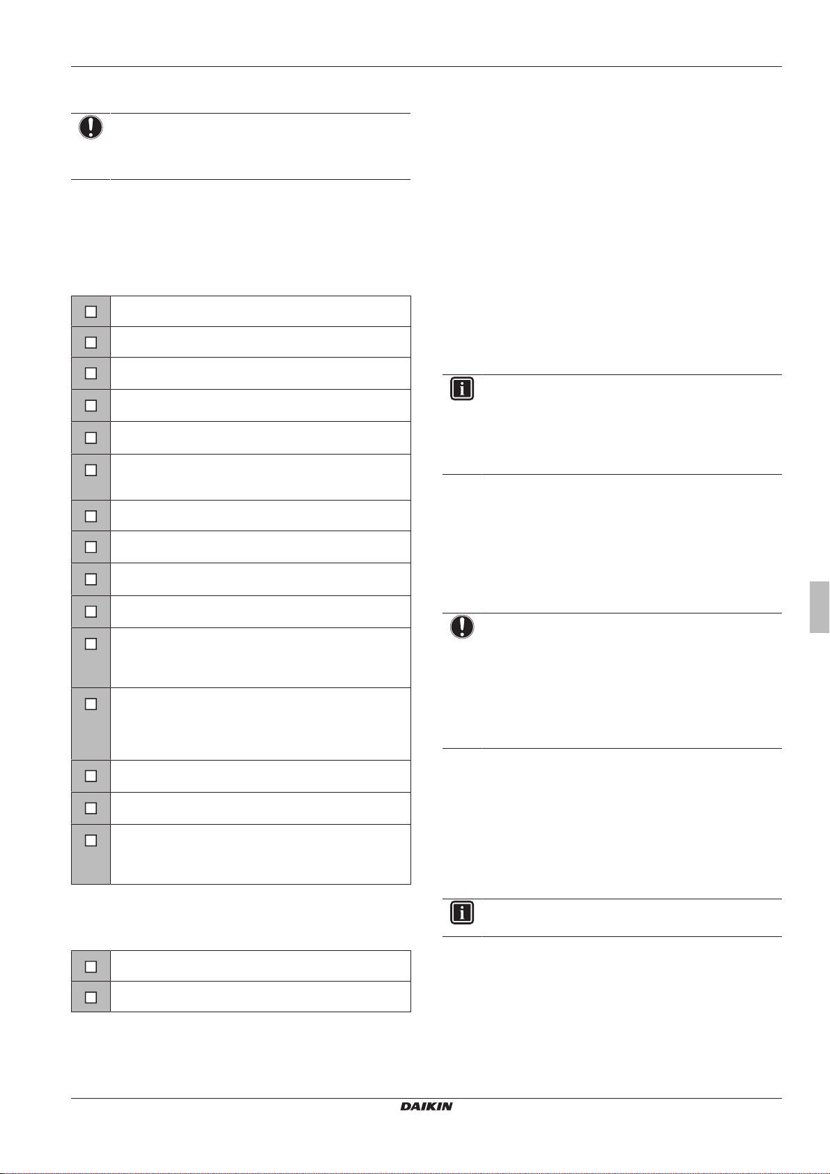
5 Inbetriebnahme
5 Inbetriebnahme
HINWEIS
Betreiben Sie das Gerät NIEMALS ohne Thermistoren
und/oder Drucksensoren/-schalter. Die Missachtung dieses
Hinweises kann zu einem Brand des Verdichters führen.
5.1 Checkliste vor Inbetriebnahme
Überprüfen Sie erst die folgenden Punkte, nachdem die Einheit
installiert worden ist. Nachdem alle nachfolgend beschriebenen
Überprüfungen durchgeführt worden sind, MUSS die Einheit
geschlossen werden. NUR dann kann sie in Betrieb genommen
werden.
Das Innengerät ist ordnungsgemäß montiert.
Das Außengerät ist ordnungsgemäß montiert.
Das System ist ordnungsgemäß geerdet und die
Erdungsklemmen sind festgezogen.
Die Versorgungsspannung stimmt mit der auf dem
Typenschild des Geräts angegebenen Spannung überein.
Es gibt KEINE losen Anschlüsse oder beschädigte
elektrische Komponenten im Schaltkasten.
Es gibt KEINE beschädigten Komponenten oder
zusammengedrückte Rohrleitungen in den Innen- und
Außengeräten.
Es gibt KEINE Kältemittel-Leckagen.
Die Kältemittelrohre (Gas und Flüssigkeit) sind
thermisch isoliert.
Es ist die richtige Rohrgröße installiert und die Rohre sind
ordnungsgemäß isoliert.
Die Sperrventile (Gas und Flüssigkeit) am Außengerät
sind vollständig geöffnet.
Die folgende bauseitige Verkabelung wurde gemäß
diesem Dokument und der gültigen Gesetzgebung
zwischen dem Außengerät und dem Innengerät
ausgeführt.
Abfluss
Darauf achten, dass Kondenswasser reibungslos abläuft.
Mögliche Folge: Kondensierendes Wasser könnte
tropfen.
Die Inneneinheit empfängt die Signale der
Benutzerschnittstelle.
Die angegebenen Kabel werden als Verbindungskabel
verwendet.
Größe und Ausführung der Sicherungen,
Hauptschaltern oder der vor Ort installierten
Schutzvorrichtungen entsprechen den Angaben in diesem
Dokument und sind NICHT übergangen worden.
5.3 So führen Sie einen Testlauf durch
Voraussetzung: Die Spannung der Stromversorgung MUSS im
angegebene Bereich liegen.
Voraussetzung: Der Probelauf kann im Kühl- oder im Heizmodus
durchgeführt werden.
Voraussetzung: Der Probelauf muss in Übereinstimmung mit den
Beschreibungen in der Betriebsanleitung der Inneneinheit
durchgeführt werden. Beim Probelauf ist zu prüfen, dass alle
Funktionen und Komponenten ordnungsgemäß funktionieren.
1 In der Betriebsart Kühlen die niedrigste programmierbare
Temperatur auswählen. In der Betriebsart Heizen die höchste
programmierbare Temperatur auswählen. Falls erforderlich
kann der Probelauf deaktiviert werden.
2 Nach Durchführung des Probelaufs die Temperatur auf eine
normale Stufe stellen. Bei Betriebsart Kühlen: 26~28°C bei
Betriebsart Heizen: 20~24°C.
3 Wird die Einheit auf AUS geschaltet, beendet das System den
Betrieb nach 3Minuten.
INFORMATION
▪ Auch wenn die Einheit ausgeschaltet ist, verbraucht sie
Strom.
▪ Wenn nach einem Stromausfall wieder Strom geliefert
wird, wird der zuvor ausgewählte Modus wieder in Kraft
gesetzt.
5.4 Inbetriebnahme des Außengeräts
Informationen zur Konfiguration und zur Inbetriebnahme des
Systems finden Sie im Installationshandbuch des Innengeräts.
6 Entsorgung
HINWEIS
Versuchen Sie auf KEINEN Fall, das System selber
auseinander zu nehmen. Die Demontage des Systems
sowie die Handhabung von Kältemittel, Öl und weiteren
Teilen MUSS in Übereinstimmung mit den entsprechenden
Vorschriften erfolgen. Die Einheiten MÜSSEN bei einer
Einrichtung aufbereitet werden, die auf
Wiederverwendung, Recycling und Wiederverwertung
spezialisiert ist.
6.1 Überblick: Entsorgung
Typischer Ablauf
Die Entsorgung des Systems umfasst üblicherweise die folgenden
Schritte:
1 System auspumpen.
2 Das System zu einer fachkundigen Einrichtung für
Wiederverwendung bringen.
5.2 Checkliste während der Inbetriebnahme
So führen Sie eine Entlüftung durch
So führen Sie einen Testlauf durch
(A)RXP20~35M5V1B
R32 Split-Baureihen
3P519299-5B – 2018.12
INFORMATION
Weitere Informationen finden Sie im Wartungshandbuch.
Installationsanleitung
21
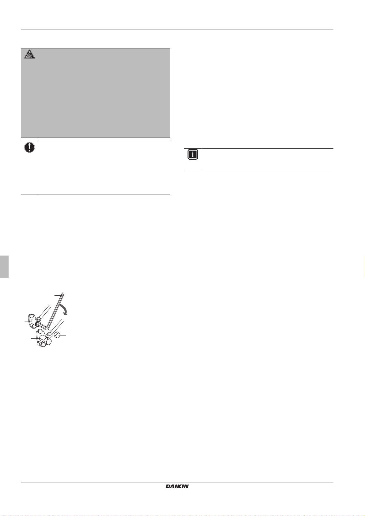
6 Entsorgung
c
b
e
d
d
a
6.2 Auspumpen
GEFAHR: EXPLOSIONSGEFAHR
Auspumpen – Kältemittelaustritt. Falls es eine Leckage
im Kältemittelkreislauf gibt und Sie das System
auspumpen wollen:
▪ NICHT die Funktion zum automatischen Auspumpen
benutzen, mit der das gesamte Kältemittel aus dem
System in der Außeneinheit gesammelt werden kann.
Mögliche Folge: Selbstentzündung und Explosion des
Verdichters, weil Luft in den arbeitenden Verdichter
gelangt.
▪ Benutzen Sie ein separates Rückgewinnungssystem,
sodass der Verdichter der Einheit NICHT in Betrieb
sein muss.
HINWEIS
Schalten Sie beim Abpumpen den Verdichter aus, bevor
Sie die Kältemittelleitungen entfernen. Wenn der
Verdichter beim Abpumpen noch arbeitet und das
Absperrventil geöffnet ist, wird Luft vom System
angesaugt. Dies kann aufgrund des ungewöhnlichen
Drucks im Kältemittelkreislauf zu einer Beschädigung des
Verdichters oder zu Schäden am System führen.
Beim Abpumpen wird das gesamte Kältemittel aus dem System in
das Außengerät abgepumpt.
1 Entfernen Sie die Ventilkappe vom Absperrventil der
Flüssigkeitsleitung und der Gasleitung.
2 Führen Sie die Zwangskühlung aus. Siehe "6.3So starten und
stoppen Sie die Zwangskühlung"auf Seite22.
3 Schließen Sie nach 5 bis 10Minuten (nach 1 oder 2 Minuten
bei sehr niedrigen Umgebungstemperaturen (<–10°C)) das
Flüssigkeitsabsperrventil mit einem Sechskantschlüssel.
4 Überprüfen Sie anhand des Manometers, ob das Vakuum
erreicht wurde.
5 Schließen Sie nach 2-3Minuten das Gasleitungs-Absperrventil
und beenden Sie die Zwangskühlung.
6.3 So starten und stoppen Sie die Zwangskühlung
Es gibt 2Methoden, um Zwangs-Kühlbetrieb zu bewirken.
▪ Methode 1. Durch Verwendung des ON/OFF Schalters der
Inneneinheit (falls bei der Inneneinheit vorhanden).
▪ Methode 2. Durch Verwendung der Benutzerschnittstelle der
Inneneinheit.
6.3.1 Zwangs-Kühlbetrieb starten/stoppen durch den EIN/AUS-Schalter der Inneneinheit
1 Den ON/OFF Schalter mindestens 5 Sekunden lang gedrückt
halten.
Ergebnis: Der Betrieb wird gestartet.
INFORMATION
Der Zwangs-Kühlbetrieb wird nach ungefähr 15 Minuten
automatisch beendet.
2 Um den Betrieb früher zu beenden, den ON/OFF Schalter
drücken.
6.3.2 Zwangs-Kühlbetrieb starten/stoppen durch die Benutzerschnittstelle der Inneneinheit
1 Die Betriebsart auf Kühlen stellen.
Eine Beschreibung des Verfahrens finden Sie unter "Einen
Probelauf durchführen" in der Installationsanleitung der Inneneinheit.
a Absperrventil der Gasleitung
b Schließrichtung
c Sechskantschlüssel
d Ventilkappe
e Flüssigkeitsleitungs-Absperrventil
Installationsanleitung
22
(A)RXP20~35M5V1B
R32 Split-Baureihen
3P519299-5B – 2018.12

7 Technische Daten
,
A
INDOOR
OUTDOOR
Informationen zu den Teilen und die Nummerierung entnehmen Sie bitte dem Elektroschaltplan der betreffenden Einheit. In der Übersicht unten
wird durch das Symbol "*" die Nummerierung jedes Teils im Teilecode dargestellt, und zwar in Form arabischer Ziffern in aufsteigender Folge.
Vereinheitlichte Schaltplan-Legende
: HAUPTSCHALTER
: ANSCHLUSS
: KONNEKTOR
: ERDE
: BAUSEITIGE VERKABELUNG
: SICHERUNG
: INNENEINHEIT
: AUSSENEINHEIT
: SCHUTZERDE
: SCHUTZERDE (SCHRAUBE)
: GLEICHRICHTER
: RELAIS-KONNEKTOR
: KURZSCHLUSS-STECKER
: ANSCHLUSS
: ANSCHLUSSLEISTE
: KABELSCHELLE
WHT : WEISS
YLW : GELB
PNK : ROSA
PRP, PPL : LILA
RED : ROT
GRN : GRÜN
GRY : GRAU
ORG : ORANGE
BLK : SCHWARZ
BLU : BLAU
BRN : BRAUN
A*P : PLATINE (LEITERPLATTE)
BS* : DRUCKTASTE EIN/AUS, BETRIEBSSCHALTER
BZ, H*O : SUMMER
C* : KONDENSATOR
AC*, CN*, E*, HA*, HE*, HL*, HN* : ANSCHLUSS, KONNEKTOR
HR*, MR*_A, MR*_B, S*, U, V,
W, X*A, K*R_*
D*, V*D : DIODE
DB* : DIODEN-BRÜCKE
DS* : DIP-SCHALTER
E*H : HEIZUNG
F*U, FU* (BEI EIGENSCHAFTEN, : SICHERUNG
SIEHE PLATINE IM INNEREN
DER EINHEIT)
FG* : KONNEKTOR (GEHÄUSEMASSE)
H* : KABELBAUM
H*P, LED*, V*L : KONTROLLLEUCHTE, LEUCHTDIODE
HAP : LEUCHTDIODE (WARTUNGSMONITOR GRÜN)
HIGH VOLTAGE : HOCHSPANNUNG
IES : INTELLIGENTES SENSORAUGE
IPM* : INTELLIGENTES POWER MODUL
K*R, KCR, KFR, KHuR, K*M : MAGNETRELAIS
L : LIVE - STROMFÜHREND
L* : ROHRSCHLANGE
L*R : DROSSELSPULE
M* : SCHRITTMOTOR
M*C : VERDICHTERMOTOR
M*F : VENTILATORMOTOR
M*P : MOTOR VON ENTWÄSSERUNGSPUMPE
M*S : SCHWENKKLAPPENMOTOR
MR*, MRCW*, MRM*, MRN* : MAGNETRELAIS
N : NEUTRAL
n=*, N=* : ANZAHL DER FERRITKERN-DURCHLÄUFE
PAM : PULSAMPLITUDENMODULATION
PCB* : PLATINE (LEITERPLATTE)
PM* : POWER MODUL
PS : SCHALTNETZTEIL
PTC* : THERMISTOR PTC
Q* : BIPOLARTRANSISTOR MIT ISOLIERTER
GATE-ELEKTRODE (IGBT)
Q*DI : FEHLERSTROM-SCHUTZSCHALTER
Q*L : ÜBERLASTSCHUTZ
Q*M : THERMOSCHALTER
R* : WIDERSTAND
R*T : THERMISTOR
RC : EMPFÄNGER
S*C : ENDSCHALTER
S*L : SCHWIMMERSCHALTER
S*NPH : DRUCK-SENSOR (HOCH)
S*NPL : DRUCK-SENSOR (NIEDRIG)
S*PH, HPS* : DRUCKSCHALTER (HOCH)
S*PL : DRUCKSCHALTER (NIEDRIG)
S*T : THERMOSTAT
S*RH : FEUCHTIGKEITSSENSOR
S*W, SW* : BETRIEBSSCHALTER
SA*, F1S : ÜBERSPANNUNGSABLEITER
SR*, WLU : SIGNALEMPFÄNGER
SS* : WAHLSCHALTER
SHEET METAL : BEFESTIGUNGSPLATTE
FÜR ANSCHLUSSLEISTE
T*R : TRANSFORMATOR
TC, TRC : SENDER
V*, R*V : VARISTOR
V*R : DIODEN-BRÜCKE
WRC : DRAHTLOSER FERNREGLER
X* : ANSCHLUSS
X*M : ANSCHLUSSLEISTE (BLOCK)
Y*E : SPULE DES ELEKTRONISCHEN
EXPANSIONSVENTILS
Y*R, Y*S : SPULE DES UMKEHR-MAGNETVENTILS
Z*C : FERRITKERN
ZF, Z*F : ENTSTÖRFILTER
Ein Teil der aktuellen technischen Daten ist auf der regionalen Daikin-Website verfügbar (öffentlich zugänglich). Die vollständigen
technischen Daten sind über das Daikin Business Portal verfügbar (Authentifizierung erforderlich).
7.1 Schaltplan
7 Technische Daten
(A)RXP20~35M5V1B
R32 Split-Baureihen
3P519299-5B – 2018.12
Installationsanleitung
23

Table des matières
Table des matières
1 À propos de la documentation 24
1.1 À propos du présent document ................................................. 24
2 À propos du carton 25
2.1 Unité extérieure ......................................................................... 25
2.1.1 Déballage de l'unité extérieure.................................... 25
2.1.2 Retrait des accessoires de l'unité extérieure .............. 25
3 Préparation 25
3.1 Préparation du lieu d'installation................................................ 25
3.1.1 Exigences du site d'installation pour l'unité extérieure 25
3.1.2 Exigences supplémentaires du site d'installation pour
l'unité extérieure dans les climats froids ..................... 25
3.2 Préparation de la tuyauterie de réfrigérant................................ 26
3.2.1 Exigences pour la tuyauterie de réfrigérant ................ 26
3.2.2 Longueur de tuyauterie de réfrigérant et différence
de hauteur................................................................... 26
3.2.3 Isolation de la tuyauterie de réfrigérant....................... 26
4 Installation 26
4.1 Ouverture des unités ................................................................. 26
4.1.1 Ouverture de l'unité extérieure.................................... 26
4.2 Montage de l'unité extérieure .................................................... 26
4.2.1 Pour fournir la structure de l'installation...................... 26
4.2.2 Installation de l'unité extérieure................................... 27
4.2.3 Pour fournir le drainage .............................................. 27
4.2.4 Protection de l'unité extérieure contre les chutes ....... 27
4.3 Raccordement de la tuyauterie de réfrigérant ........................... 27
4.3.1 Concernant le raccordement de la tuyauterie de
réfrigérant.................................................................... 27
4.3.2 Précautions lors du raccordement de la tuyauterie de
réfrigérant.................................................................... 28
4.3.3 Raccordement du tuyau de réfrigérant à l'unité
extérieure .................................................................... 28
4.4 Vérification de la tuyauterie de réfrigérant................................. 28
4.4.1 Recherche de fuites.................................................... 28
4.4.2 Procédure de séchage sous vide................................ 28
4.5 Charge du réfrigérant ................................................................ 29
4.5.1 À propos du chargement du réfrigérant ...................... 29
4.5.2 A propos du réfrigérant ............................................... 29
4.5.3 Détermination de la quantité de réfrigérant
complémentaire .......................................................... 29
4.5.4 Détermination de la quantité de recharge complète ... 30
4.5.5 Chargement de réfrigérant supplémentaire ................ 30
4.5.6 Mise en place de l'étiquette concernant les gaz
fluorés à effet de serre ................................................ 30
4.6 Raccordement du câblage électrique........................................ 30
4.6.1 Spécifications des composants de câblage standard. 30
4.6.2 Raccordement du câblage électrique sur l'unité
extérieure .................................................................... 31
4.7 Finalisation de l'installation de l'unité extérieure ....................... 31
4.7.1 Finalisation de l'installation de l'unité extérieure......... 31
4.7.2 Fermeture de l'unité extérieure ................................... 31
7 Données techniques 34
7.1 Schéma de câblage.................................................................... 34
1 À propos de la
documentation
1.1 À propos du présent document
INFORMATIONS
Vérifiez que l'utilisateur dispose de la version imprimée de
la documentation et demandez-lui de la conserver pour s'y
référer ultérieurement.
Public visé
Installateurs agréés
Documentation
Le présent document fait partie d'un ensemble. L'ensemble complet
comprend les documents suivants:
▪ Précautions de sécurité générales:
▪ Instructions de sécurité à lire avant l'installation
▪ Format: Papier (dans le carton de l'unité extérieure)
▪ Manuel d'installation de l'unité extérieure:
▪ Instructions d'installation
▪ Format: Papier (dans le carton de l'unité extérieure)
▪ Guide de référence installateur:
▪ Préparation de l'installation, données de référence…
▪ Format: Fichiers numériques sur http://www.daikineurope.com/
support-and-manuals/product-information/
Il est possible que les dernières révisions de la documentation
fournie soient disponibles sur le site Web Daikin de votre région ou
via votre revendeur.
La documentation d'origine est rédigée en anglais. Toutes les autres
langues sont des traductions.
Données techniques
▪ Un sous-ensemble des récentes données techniques est
disponible sur le site régional Daikin (accessible au public).
▪ L'ensemble complet des dernières données techniques est
disponible sur l'extranet Daikin (authentification requise).
5 Mise en service 31
5.1 Liste de contrôle avant la mise en service ................................ 31
5.2 Liste de vérifications pendant la mise en service ...................... 31
5.3 Essai de fonctionnement ........................................................... 32
5.4 Démarrage de l'unité extérieure ................................................ 32
6 Mise au rebut 32
6.1 Aperçu: Mise au rebut ............................................................... 32
6.2 Aspiration .................................................................................. 32
6.3 Démarrage et arrêt du rafraîchissement forcé .......................... 33
6.3.1 Pour démarrer/arrêter le refroidissement forcé à
l'aide du commutateur MARCHE/ARRÊT................... 33
6.3.2 Pour démarrer/arrêter le refroidissement forcé à
l'aide de l'interface utilisateur de l'unité intérieure....... 33
Manuel d'installation
24
(A)RXP20~35M5V1B
Série Split R32
3P519299-5B – 2018.12
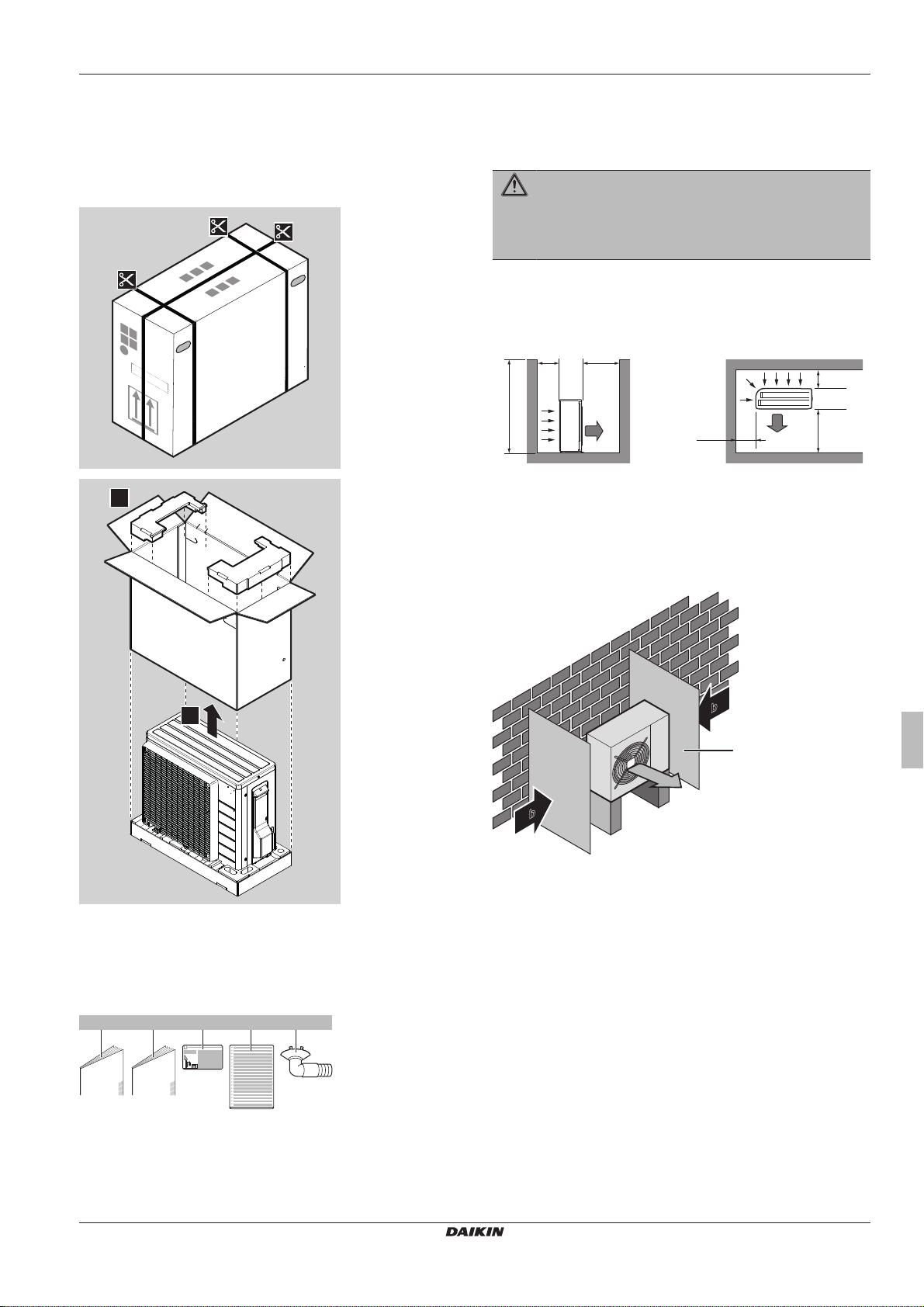
2 À propos du carton
1
2
b ec d
1×
a
1× 1× 1× 1×
≤1200
>150
>150
>50
>300
>300
(mm)(mm)
a
b
b
a
b
a
b
c
2 À propos du carton
2.1 Unité extérieure
2.1.1 Déballage de l'unité extérieure
3 Préparation
3.1 Préparation du lieu d'installation
AVERTISSEMENT
L'appareil sera stocké dans une pièce sans sources
d'allumage fonctionnant en permanence (exemple:
flammes nues, un appareil fonctionnant au gaz ou un
chauffage électrique).
3.1.1 Exigences du site d'installation pour l'unité extérieure
Prenez les directives suivantes en compte en matière d'espacement:
a Bouche de soufflage
b Entrée d'air
Nous vous recommandons d'installer une chicane lorsque la sortie
d'air est exposée au vent.
Nous vous recommandons d'installer l'unité extérieure avec l'entrée
d'air face au mur et NON directement exposée au vent.
2.1.2 Retrait des accessoires de l'unité extérieure
1 Soulevez l'unité extérieure.
2 Retirez les accessoires au bas de l'emballage.
a Consignes de sécurité générales
b Manuel d'installation de l'unité extérieure
c Etiquette de gaz à effet de serre fluorés
d Etiquette multilingue de gaz à effet de serre fluorés
(A)RXP20~35M5V1B
Série Split R32
3P519299-5B – 2018.12
e Bouchon de purge (se situe au fond de l'emballage)
a Chicane
b Sens prédominant du vent
c Sortie d'air
3.1.2 Exigences supplémentaires du site d'installation pour l'unité extérieure dans les climats froids
Protégez l'unité extérieure des chutes de neige directes et veillez à
ce que l'unité extérieure ne soit JAMAIS ensevelie sous la neige.
Manuel d'installation
25
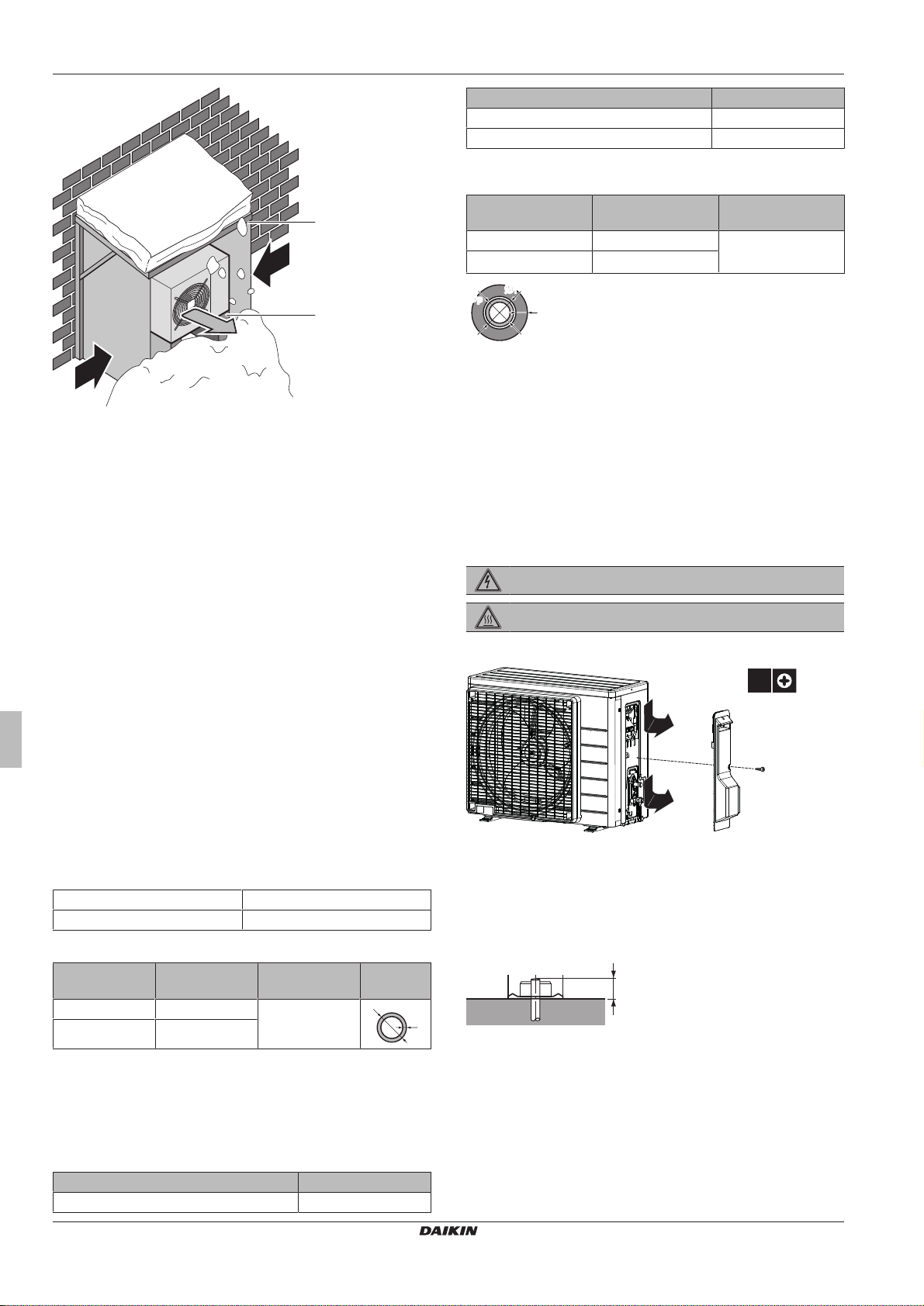
4 Installation
a
b
c
c
d
t
Ø
ØiØ
i
t
ØpØ
p
1×
2
1
2
20 mm
Quoi? Distance
Longueur admissible minimale du tuyau 1,5m
Différence de hauteur maximale admise 12m
3.2.3 Isolation de la tuyauterie de réfrigérant
a Protection ou abri contre la neige
b Socle
c Sens prédominant du vent
d Sortie d'air
Dans tous les cas, prévoyez au moins 300mm d'espace libre sous
l'unité. De plus, assurez-vous que l'unité est positionnée à au moins
100 mm au-dessus du niveau maximum de neige attendu. Voir
"4.2 Montage de l'unité extérieure" à la page 26 pour plus de
détails.
Dans les régions avec de très fortes chutes de neige, il est très
important de sélectionner un lieu d'installation où la neige n'affectera
PAS l'unité. Si des chutes de neige latérales sont possibles, veillez à
ce que le serpentin de l'échangeur de chaleur ne soit PAS affecté
par la neige. Si nécessaire, installez une protection ou un abri contre
la neige et un support.
Diamètre extérieur
du tuyau (Øp)
6,4mm (1/4") 8~10mm ≥10mm
9,5mm (3/8") 12~15mm
Si la température est supérieure à 30°C et si l'humidité relative est
supérieure à 80%, l'épaisseur des matériaux d'isolation doit alors
être d'au moins 20 mm afin d'éviter toute condensation sur la
surface du matériau isolant.
Diamètre intérieur
de l'isolation (Øi)
Épaisseur de
l'isolation (t)
4 Installation
4.1 Ouverture des unités
4.1.1 Ouverture de l'unité extérieure
DANGER: RISQUE D'ÉLECTROCUTION
DANGER: RISQUE DE BRÛLURE
Voir également
2 4.2 Montage de l'unité extérieure [}26]
3.2 Préparation de la tuyauterie de réfrigérant
3.2.1 Exigences pour la tuyauterie de réfrigérant
▪ Matériau des tuyaux: Cuivre sans soudure désoxydé à l'acide
phosphorique.
▪ Diamètre de tuyauterie:
Tuyauterie du liquide Ø6.4mm (1/4")
Tuyauterie de gaz Ø9.5mm (3/8")
▪ Degré de trempe de la canalisation et épaisseur de paroi:
Diamètre
extérieur (Ø)
6,4mm (1/4") Recuit (O) ≥0,8mm
9,5mm (3/8") Recuit (O)
(a) En fonction de la législation en vigueur et de la pression de
Degré de
trempe
travail maximale de l'unité (voir "PS High" sur la plaquette
signalétique), une épaisseur de tuyauterie plus grande peut
être requise.
Épaisseur (t)
(a)
3.2.2 Longueur de tuyauterie de réfrigérant et différence de hauteur
Quoi? Distance
Longueur admissible maximale du tuyau 15m
Manuel d'installation
26
4.2 Montage de l'unité extérieure
4.2.1 Pour fournir la structure de l'installation
Préparez 4 jeux de boulons d'ancrage, d'écrous et de rondelles M8
ou M10 (à fournir).
(A)RXP20~35M5V1B
Série Split R32
3P519299-5B – 2018.12
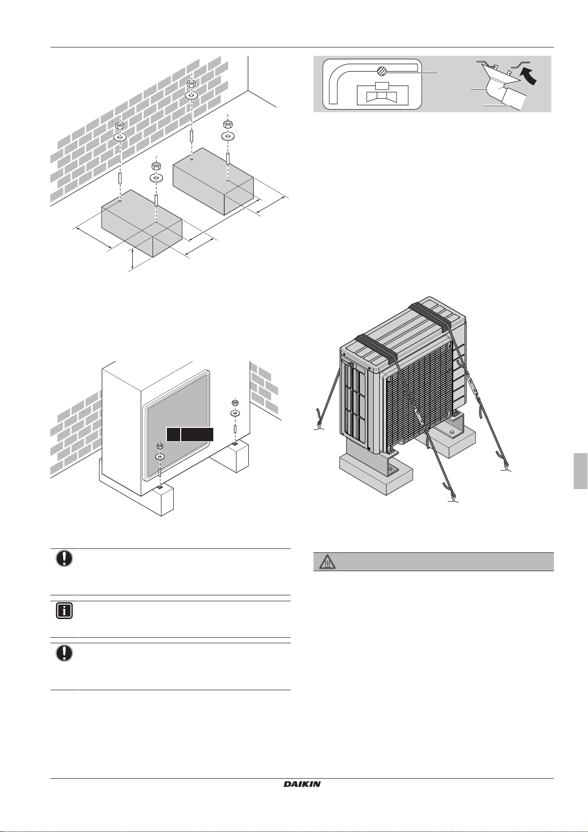
300
470
192
(mm)
192
>300
Dans tous les cas, prévoyez au moins 300mm d'espace libre sous
4× M8/M10
b
c
d
a
l'unité. De plus, assurez-vous que l'unité est positionné à au moins
100mm au-dessus du niveau maximum de neige attendu. Dans ce
cas, nous vous recommandons d'installer un socle.
4 Installation
a Orifice de drainage
b Bâti inférieur
c Bouchon de drainage
d Flexible (non fourni)
4.2.4 Protection de l'unité extérieure contre les chutes
Si l'unité est installée dans un lieu où des vents forts peuvent la faire
basculer, prenez les mesures suivantes:
1 Préparez 2 câbles comme indiqué sur l'illustration suivante (à
fournir).
2 Placez les 2câbles sur l'unité extérieure.
3 Insérez une feuille en caoutchouc entre les câbles et l'unité
extérieure de manière à ce que les câbles ne rayent pas la
peinture (à fournir).
4 Fixez les extrémités des câbles et serrez-les.
4.2.2 Installation de l'unité extérieure
4.2.3 Pour fournir le drainage
REMARQUE
Si l'unité est installée dans un climat froid, prenez les
mesures adéquates pour que le condensat évacué NE
puisse PAS geler.
INFORMATIONS
Pour en savoir plus sur les options disponibles, contactez
votre revendeur.
REMARQUE
Laissez un espace libre d'au moins 300mm sous l'unité.
Veillez également à ce que l'unité soit positionnée au
moins 100mm au-dessus du niveau de neige envisagé.
1 Utilisez un bouchon de drainage pour le drainage.
2 Utilisez un flexible de Ø16(non fourni).
(A)RXP20~35M5V1B
Série Split R32
3P519299-5B – 2018.12
4.3 Raccordement de la tuyauterie de réfrigérant
DANGER: RISQUE DE BRÛLURE
4.3.1 Concernant le raccordement de la tuyauterie de réfrigérant
Avant de raccorder la tuyauterie de réfrigérant
Assurez-vous que l'unité extérieure et intérieure sont montées.
Ordre de montage habituel
Le raccordement de la tuyauterie de réfrigérant implique:
▪ Raccordement de la tuyauterie de réfrigérant à l'unité intérieure
▪ Raccordement de la tuyauterie de réfrigérant à l'unité extérieure
▪ Isolation de la tuyauterie de réfrigérant
▪ Gardez en tête les consignes de:
▪ Pliage des tuyaux
▪ Évasement de l'extrémité des tuyaux
▪ Utilisation des vannes d'arrêt
Manuel d'installation
27
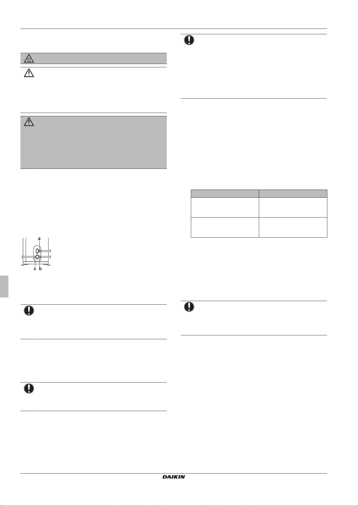
4 Installation
a
bc
4.3.2 Précautions lors du raccordement de la tuyauterie de réfrigérant
DANGER: RISQUE DE BRÛLURE
ATTENTION
▪ Utilisez l'écrou évasé fixé à l'unité principale.
▪ Pour éviter les fuites de gaz, n'appliquez de l'huile de
réfrigération qu'à l'intérieur du raccord. Utilisez de
l'huile réfrigérante pour R32.
▪ Ne réutilisez PAS les joints.
AVERTISSEMENT
Branchez fermement la tuyauterie de réfrigérant avant de
faire fonctionner le compresseur. En effet, si la tuyauterie
du réfrigérant n'est PAS branchée et que la vanne d'arrêt
est ouverte alors que le compresseur fonctionne, de l'air
sera aspiré et provoquera une pression anormale dans le
cycle de réfrigération. Cela risque d'endommager
l'équipement et de blesser des personnes.
4.3.3 Raccordement du tuyau de réfrigérant à l'unité extérieure
▪ Longueur de la tuyauterie. Maintenez la tuyauterie sur place la
plus courte possible.
▪ Protection de tuyauterie. Protégez la tuyauterie sur place contre
les dommages physiques.
1 Raccordez le raccord du réfrigérant liquide de l'unité intérieure
à la vanne d'arrêt du liquide de l'unité extérieure.
REMARQUE
Veillez à utiliser une solution de détection de bulles
recommandée par le revendeur. N'utilisez pas d'eau
savonneuse qui risque de provoquer des fissures des
écrous évasés (l'eau savonneuse peut contenir du sel qui
absorbe l'humidité qui se mettra à geler lorsque le tuyau
refroidit) et/ou d'entraîner la corrosion des raccords évasés
(l'eau savonneuse peut contenir de l'ammoniaque qui
provoque un effet corrosif entre l'écrou évasé en laiton et
l'évasement en cuivre).
1 Chargez le système avec de l'azote jusqu'à une pression de
jauge d'au moins 200 kPa (2bar). Une pression de 3000kPa
(30bar) est recommandée pour détecter les petites fuites.
2 Vérifiez l'étanchéité en appliquant une solution de détection de
bulles sur tous les raccords.
3 Purgez entièrement l'azote.
4.4.2 Procédure de séchage sous vide
1 Mettez le système sous vide jusqu'à ce que la pression
indiquée par le manifold soit de −0,1MPa (−1bar).
2 Laissez le système pendant 4 à 5 minutes et vérifiez la
pression:
Si la pression… Alors…
Ne change pas Il n'y a pas d'humidité dans le
système. La procédure est
terminée.
Augmente Il y a de l'humidité dans le
système. Passez à l'étape
suivante.
a Vanne d'arrêt du liquide
b Vanne d'arrêt du gaz
c Orifice de service
2 Connectez le raccord du réfrigérant gazeux de l'unité intérieure
à la vanne d'arrêt du gaz de l'unité extérieure.
REMARQUE
Nous vous recommandons d'installer la tuyauterie de
réfrigérant entre l'unité intérieure et l'unité extérieure dans
un conduit ou d'enrouler la tuyauterie de réfrigérant dans
du ruban de finition.
4.4 Vérification de la tuyauterie de réfrigérant
4.4.1 Recherche de fuites
REMARQUE
Ne dépassez PAS la pression de service maximale
autorisée pour l'unité (voir “PS High” sur la plaque
signalétique de l'unité).
3 Aspirez le système pendant au moins 2heures à une pression
de collecteur de −0,1MPa (−1bar).
4 Après avoir arrêté la pompe, vérifiez la pression pendant au
moins 1heure.
5 Si vous n'atteignez PAS le vide cible ou si vous ne pouvez pas
maintenir le vide pendant 1heure, procédez comme suit:
▪ Vérifiez de nouveau l'étanchéité.
▪ Procédez de nouveau au séchage à vide.
REMARQUE
Veillez à ouvrir les vannes d'arrêt après l'installation de la
tuyauterie de réfrigérant et avoir effectué le séchage à sec.
Faire fonctionner le système avec les vannes d'arrêt
fermées peut casser le compresseur.
Manuel d'installation
28
(A)RXP20~35M5V1B
Série Split R32
3P519299-5B – 2018.12
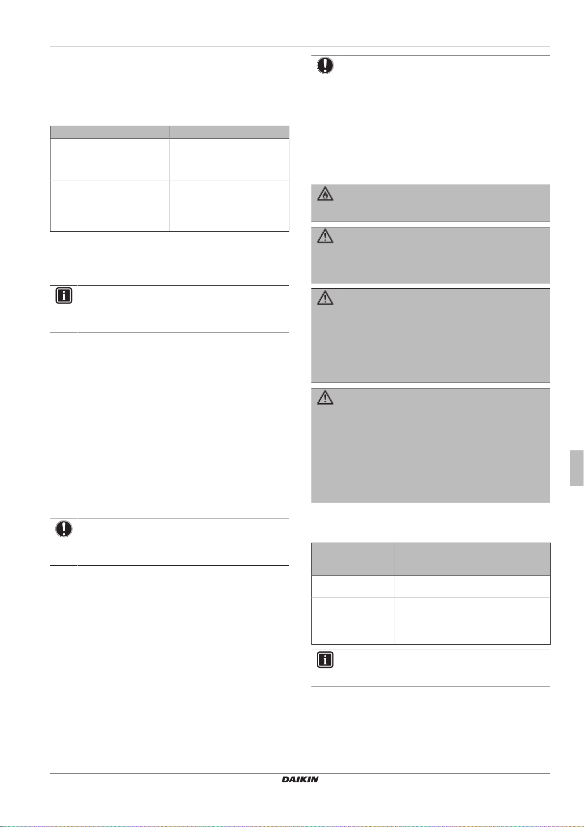
4 Installation
4.5 Charge du réfrigérant
4.5.1 À propos du chargement du réfrigérant
L'unité extérieure est chargée de réfrigérant en usine, mais dans
certains cas, ce qui suit peut être nécessaire:
Quoi Quand
Charge de réfrigérant
supplémentaire
Recharge complète de
réfrigérant
Charge de réfrigérant supplémentaire
Avant de charger du réfrigérant supplémentaire, assurez-vous que la
tuyauterie de réfrigérant externe de l'unité extérieure est vérifiée
(test de fuite, séchage à vide).
INFORMATIONS
En fonction des unités et/ou des conditions d'installation, il
peut être nécessaire de brancher le câblage électrique
avant de pouvoir charger le réfrigérant.
Flux de travail typique – La recharge de réfrigérant supplémentaire
consiste généralement en les étapes suivantes:
1 Déterminer si et combien il faut rajouter de charge.
2 Si nécessaire, recharge de réfrigérant.
3 Compléter l'étiquette des gaz à effet de serre fluorés et la fixer à
l'intérieur de l'unité extérieure.
Recharge complète de réfrigérant
Avant de recharger complètement le réfrigérant, assurez-vous que
ce qui suit est effectué:
1 Tout le réfrigérant a été récupéré du circuit.
2 La tuyauterie de réfrigérant externe de l'unité extérieure est
vérifiée (test de fuite, séchage à vide).
3 Le séchage à vide de la tuyauterie de réfrigérant interne de
l'unité extérieure est effectué.
REMARQUE
Avant de recharger complètement, effectuez également un
séchage à vide de la tuyauterie interne de réfrigérant de
l'unité extérieure.
Flux de travail typique – La recharge de réfrigérant supplémentaire
consiste généralement en les étapes suivantes:
1 Déterminer combien de réfrigérant charger.
2 Charge du réfrigérant.
3 Compléter l'étiquette des gaz à effet de serre fluorés et la fixer à
l'intérieur de l'unité extérieure.
Lorsque la longueur de la
tuyauterie de liquide totale est
supérieure à celle spécifiée (voir
plus loin).
Exemple:
▪ Lors de la relocalisation du
système.
▪ Après une fuite.
REMARQUE
En Europe, les émissions de gaz à effet de serre de la
charge totale de réfrigérant dans le système (exprimées en
équivalent tonnes CO2) sont utilisées pour déterminer les
intervalles de maintenance. Suivez la législation en
vigueur.
Formule pour calculer les émissions de gaz à effet de
serre: Valeur GWP du réfrigérant × charge de réfrigérant
totale [en kg] / 1000
Veuillez contacter votre installateur pour de plus amples
informations.
AVERTISSEMENT: MATÉRIAU INFLAMMABLE
Le réfrigérant à l'intérieur de cette unité est légèrement
inflammable.
AVERTISSEMENT
L'appareil sera stocké dans une pièce sans sources
d'allumage fonctionnant en permanence (exemple:
flammes nues, un appareil fonctionnant au gaz ou un
chauffage électrique).
AVERTISSEMENT
▪ Ne percez et ne brûlez PAS des pièces du cycle de
réfrigérant.
▪ N'utilisez PAS de produit de nettoyage ou de moyens
d'accélérer le processus de dégivrage autres que ceux
recommandés par le fabricant.
▪ Sachez que le réfrigérant à l'intérieur du système est
sans odeur.
AVERTISSEMENT
Le réfrigérant à l'intérieur de cette unité est légèrement
inflammable, mais ne fuit PAS normalement. Si du
réfrigérant fuit dans la pièce et entre en contact avec la
flamme d'un brûleur, d'un chauffage ou d'une cuisinière, il
y a un risque d'incendie ou de formation de gaz nocifs.
Eteignez tout dispositif de chauffage à combustible,
ventiler la pièce et contacter le revendeur de l'unité.
N'utilisez PAS l'unité tant qu'une personne compétente n'a
pas confirmé que la fuite de réfrigérant est colmatée.
4.5.3 Détermination de la quantité de réfrigérant complémentaire
Si la longueur totale
de la tuyauterie de
liquide est de…
≤10m N'AJOUTEZ PAS de réfrigérant
complémentaire.
>10m R=(longueur totale (m) de la tuyauterie de
liquide–10m)×0,020
R=charge supplémentaire (kg) (unités
arrondies à 0,01kg près)
Alors…
4.5.2 A propos du réfrigérant
Ce produit contient des gaz à effet de serre fluorés. Ne laissez PAS
les gaz s'échapper dans l'atmosphère.
Type de réfrigérant: R32
Potentiel de réchauffement global (GWP): 675
(A)RXP20~35M5V1B
Série Split R32
3P519299-5B – 2018.12
INFORMATIONS
La longueur de tuyau correspond à la longueur dans un
sens du tuyau de liquide.
Manuel d'installation
29
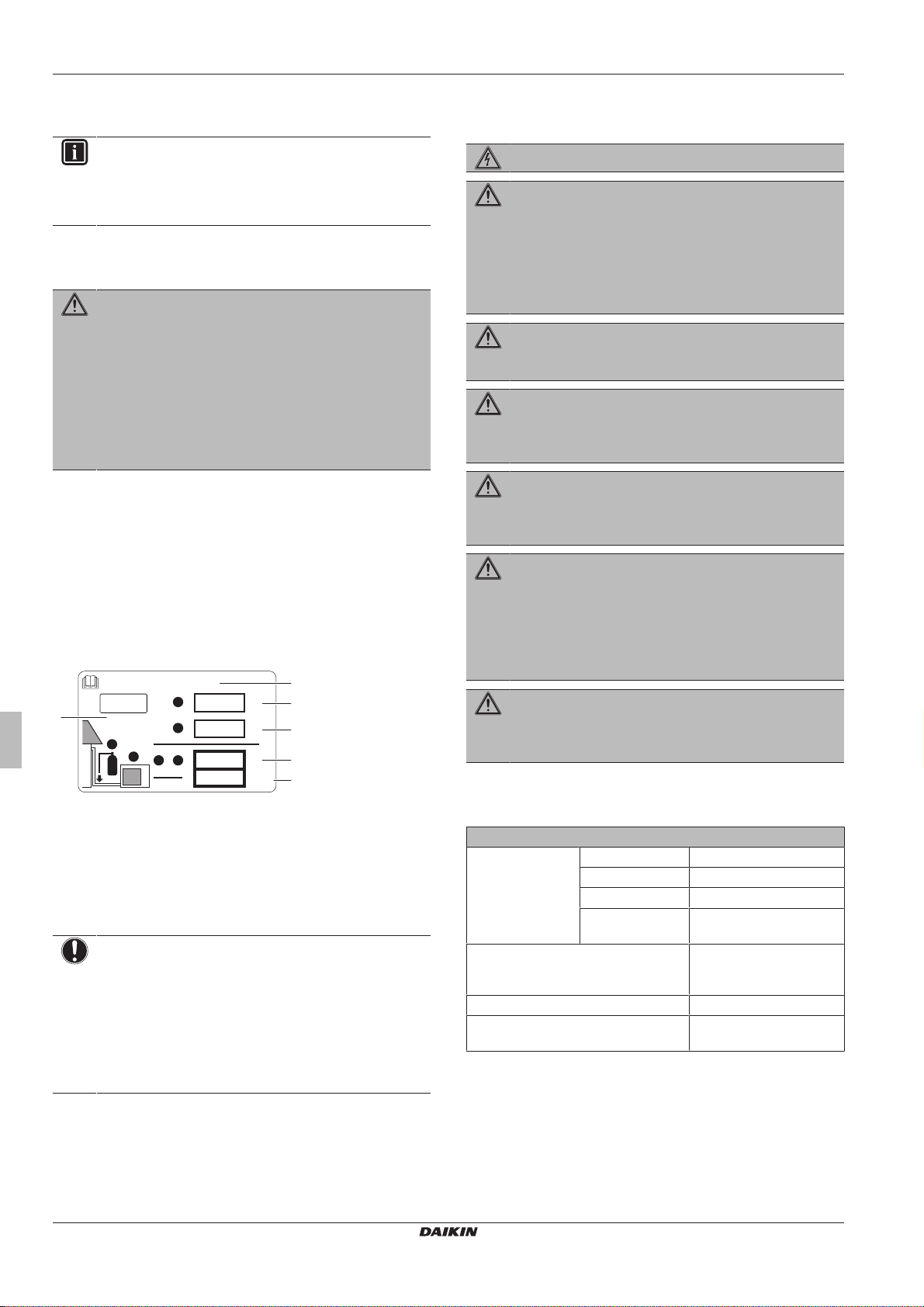
4 Installation
b
Contains fluorinated greenhouse gases
2
1
1
1
2
2
kg
tCO2eq
GWP × kg
1000
=
=
+
kg
=
kg
=
GWP: XXX
RXXX
a
f
c
d
e
4.5.4 Détermination de la quantité de recharge complète
INFORMATIONS
Si une recharge complète est nécessaire, la charge totale
de réfrigérant est la suivante: charge de réfrigérant en
usine (reportez-vous à la plaque signalétique de l'unité) +
quantité supplémentaire déterminée.
4.5.5 Chargement de réfrigérant supplémentaire
AVERTISSEMENT
▪ Utilisez uniquement du réfrigérant R32. D'autres
substances peuvent entraîner des explosions et des
accidents.
▪ Le R32 contient des gaz à effet de serre fluorés. Son
potentiel de réchauffement global (GWP) est de 675.
NE laissez PAS ces gaz s'échapper dans l'atmosphère.
▪ Lorsque vous chargez du réfrigérant, utilisez
TOUJOURS des gants de protection et des lunettes de
sécurité.
Condition requise: Avant de charger du réfrigérant, assurez-vous
que le tuyau de réfrigérant est connecté et vérifié (test de fuite et
séchage à vide).
1 Raccordez le cylindre du réfrigérant à l'orifice d'entretien.
2 Chargez la quantité de réfrigérant supplémentaire.
3 Ouvrez la vanne d'arrêt du gaz.
4.5.6 Mise en place de l'étiquette concernant les gaz fluorés à effet de serre
1 Remplissez l'étiquette comme suit:
4.6 Raccordement du câblage électrique
DANGER: RISQUE D'ÉLECTROCUTION
AVERTISSEMENT
▪ Le câblage DOIT être effectué par un électricien agréé
et DOIT être conforme à la législation en vigueur.
▪ Procédez aux raccords électriques sur le câblage fixe.
▪ Tous les composants fournis sur site et l'ensemble de
l'installation électrique DOIVENT être conformes à la
législation en vigueur.
AVERTISSEMENT
Utilisez TOUJOURS un câble multiconducteur pour
l'alimentation électrique.
AVERTISSEMENT
Si le câble d'alimentation est endommagé, il DOIT être
remplacé par le fabricant, son agent de service ou des
personnes qualifiées afin d'éviter tout danger.
AVERTISSEMENT
Ne branchez PAS l'alimentation à l'unité intérieure. Cela
pourrait provoquer une décharge électrique ou un
incendie.
AVERTISSEMENT
▪ N'utilisez PAS d'éléments électriques achetés
localement dans le produit.
▪ Ne branchez PAS l'alimentation de la pompe
d'évacuation, etc. sur le bornier de transmission. Cela
pourrait provoquer une décharge électrique ou un
incendie.
a Si une étiquette de gaz à effet de serre fluorée multilingue
est livrée avec l'unité (voir accessoires), décollez la langue
appropriée et collez-la par-dessus a.
b Charge de réfrigérant en usine: reportez-vous à la plaque
signalétique de l'unité
c Quantité de réfrigérant supplémentaire chargée
d Charge de réfrigérant totale
e Emissions de gaz à effet de serre de la charge totale de
réfrigérant exprimées en tonnes d'équivalent de CO
f GWP = Potentiel de réchauffement global
2
REMARQUE
En Europe, les émissions de gaz à effet de serre de la
charge de réfrigérant totale dans le système (exprimées en
tonnes d'équivalent de CO2) sont utilisées pour déterminer
les intervalles de maintenance. Suivez la législation
applicable.
Formule pour calculer les émissions de gaz à effet de
serre: la valeur GWP du réfrigérant × la charge de
réfrigérant totale [en kg] / 1000
2 Apposez l'étiquette à l'intérieur de l'unité extérieure, à côté des
vannes d'arrêt du gaz et du liquide.
AVERTISSEMENT
Tenez le câblage d'interconnexion éloigné des tuyaux en
cuivre sans isolation thermique, car ces tuyaux seront très
chauds.
4.6.1 Spécifications des composants de câblage standard
Composant
Câble
d'alimentation
Câblage d'interconnexion
(intérieur↔extérieur)
Fusible de remplacement recommandé 16A
Disjoncteur de fuite à la terre DOIVENT se conformer à
Tension 220~240V
Phase 1~
Fréquence 50Hz
Taille des câbles DOIVENT se conformer à
la législation en vigueur
Câble à 4 conducteurs
≥1,5 mm² et applicable
pour le 220~240 V
la législation en vigueur
Manuel d'installation
30
(A)RXP20~35M5V1B
Série Split R32
3P519299-5B – 2018.12
 Loading...