

Daikin FTXN25KEV1B, FTXN35KEV1B, RXN35KEV1B, RXN25KEV1B Service Manual

Service
Manual
Inverter Pair
Wall Mounted Type K-Series
SiBE041102_A
[Applied Models]
O
Inverter Pair : Heat Pump

SiBE041102_A
i Table of Contents
Inverter Pair
Wall Mounted Type
K-Series
zHeat Pump
Indoor Unit
FTXN25KEV1B
FTXN35KEV1B
Outdoor Unit
RXN25KEV1B
RXN35KEV1B

SiBE041102_A
Table of Contents ii
1. Introduction .............................................................................................v
1.1 Safety Cautions ........................................................................................ v
1.2 Used Icons .............................................................................................. ix
Part 1 List of Functions ................................................................1
1. Functions.................................................................................................2
Part 2 Specifications .................................................................... 3
1. Specifications..........................................................................................4
Part 3 Printed Circuit Board Connector Wiring Diagram ............. 5
1. Indoor Unit...............................................................................................6
2. Outdoor Unit............................................................................................8
Part 4 Function and Control.......................................................... 9
1. Main Functions......................................................................................10
1.1 Temperature Control ..............................................................................10
1.2 Frequency Principle................................................................................10
1.3 Airflow Direction Control.........................................................................12
1.4 Fan Speed Control for Indoor Unit .........................................................13
1.5 Program Dry Operation ..........................................................................14
1.6 Automatic Operation...............................................................................15
1.7 Thermostat Control.................................................................................16
1.8 NIGHT SET Mode ..................................................................................17
1.9 ECONO Operation .................................................................................18
1.10 Inverter POWERFUL Operation .............................................................19
1.11 Other Functions......................................................................................20
2. Function of Thermistor ..........................................................................21
3. Control Specification .............................................................................22
3.1 Mode Hierarchy ......................................................................................22
3.2 Frequency Control..................................................................................23
3.3 Controls at Mode Changing / Start-up....................................................25
3.4 Discharge Pipe Temperature Control.....................................................26
3.5 Input Current Control ..............................................................................27
3.6 Freeze-up Protection Control .................................................................28
3.7 Heating Peak-cut Control .......................................................................28
3.8 Outdoor Fan Control...............................................................................29
3.9 Liquid Compression Protection Function................................................29
3.10 Defrost Control .......................................................................................30
3.11 Electronic Expansion Valve Control .......................................................31
3.12 Malfunctions ...........................................................................................34
Part 5 Operation Manual ............................................................. 35
1. System Configuration............................................................................36
2. Operation Manual..................................................................................37
2.1 Remote Controller ..................................................................................37
2.2 AUTO · DRY · COOL · HEAT · FAN Operation ......................................38
2.3 Adjusting the Airflow Direction................................................................40

SiBE041102_A
iii Table of Contents
2.4 COMFORT AIRFLOW Operation ...........................................................42
2.5 POWERFUL Operation ..........................................................................43
2.6 ECONO Operation .................................................................................44
2.7 OFF TIMER Operation ...........................................................................45
2.8 ON TIMER Operation .............................................................................46
Part 6 Service Diagnosis.............................................................47
1. Troubleshooting with LED.....................................................................48
1.1 Indoor Unit..............................................................................................48
1.2 Outdoor Unit ...........................................................................................48
2. Problem Symptoms and Measures.......................................................49
3. Service Check Function ........................................................................50
4. Troubleshooting ....................................................................................53
4.1 Error Codes and Description ..................................................................53
4.2 Indoor Unit PCB Abnormality .................................................................54
4.3 Freeze-up Protection Control or Heating Peak-cut Control....................55
4.4 Fan Motor (AC Motor) or Related Abnormality.......................................57
4.5 Thermistor or Related Abnormality (Indoor Unit)....................................59
4.6 Signal Transmission Error (between Indoor Unit and Outdoor Unit)......60
4.7 Unspecified Voltage (between Indoor Unit and Outdoor Unit) ...............62
4.8 Outdoor Unit PCB Abnormality...............................................................63
4.9 OL Activation (Compressor Overload) ...................................................64
4.10 Compressor Lock ...................................................................................65
4.11 Input Overcurrent Detection ...................................................................66
4.12 Four Way Valve Abnormality..................................................................67
4.13 Discharge Pipe Temperature Control.....................................................69
4.14 High Pressure Control in Cooling ...........................................................70
4.15 Compressor System Sensor Abnormality ..............................................71
4.16 Position Sensor Abnormality ..................................................................72
4.17 DC Voltage / Current Sensor Abnormality..............................................74
4.18 Thermistor or Related Abnormality (Outdoor Unit) .................................75
4.19 Electrical Box Temperature Rise ............................................................77
4.20 Radiation Fin Temperature Rise ............................................................79
4.21 Output Overcurrent Detection ................................................................81
4.22 Refrigerant Shortage ..............................................................................83
4.23 Low-voltage Detection or Over-voltage Detection..................................85
5. Check ....................................................................................................87
5.1 Thermistor Resistance Check ................................................................87
5.2 Hall IC Check .........................................................................................88
5.3 Power Supply Waveforms Check...........................................................88
5.4 Electronic Expansion Valve Check.........................................................89
5.5 Four Way Valve Performance Check .....................................................90
5.6 Inverter Unit Refrigerant System Check.................................................90
5.7 “Inverter Checker” Check .......................................................................91
5.8 Installation Condition Check ...................................................................92
5.9 Discharge Pressure Check.....................................................................93
5.10 Outdoor Fan System Check ...................................................................93
5.11 Main Circuit Short Check........................................................................94
5.12 Power Module Check .............................................................................94

SiBE041102_A
Table of Contents iv
Part 7 Removal Procedure .......................................................... 95
1. Indoor Unit.............................................................................................96
1.1 Removal of Air Filters .............................................................................96
1.2 Removal of Horizontal Blade..................................................................98
1.3 Removal of Front Panel........................................................................100
1.4 Removal of Front Grille ........................................................................101
1.5 Removal of Electrical Box / Vertical Blades .........................................102
1.6 Removal of Swing Motor / PCBs ..........................................................107
1.7 Removal of Indoor Heat Exchanger .....................................................111
1.8 Removal of Fan Rotor / Fan Motor.......................................................114
1.9 Exchange of Drain Hose (Piping Direction) ..........................................117
2. Outdoor Unit........................................................................................118
2.1 Removal of Outer Panels .....................................................................118
2.2 Removal of Outdoor Fan / Fan Motor...................................................120
2.3 Removal of Electrical Box / PCB ..........................................................122
2.4 Removal of Sound Blankets .................................................................130
2.5 Removal of Four Way Valve.................................................................132
2.6 Removal of Compressor.......................................................................135
Part 8 Trial Operation and Field Settings.................................136
1. Pump Down Operation........................................................................137
2. Forced Cooling Operation...................................................................138
3. Trial Operation ....................................................................................139
4. Field Settings ......................................................................................140
4.1 When 2 Units are Installed in 1 Room ..................................................140
4.2 Jumper Settings ...................................................................................140
5. Application of Silicon Grease to a Power Transistor and
a Diode Bridge ....................................................................................141
Part 9 Appendix......................................................................... 142
1. Piping Diagrams..................................................................................143
1.1 Indoor Unit............................................................................................143
1.2 Outdoor Unit .........................................................................................144
2. Wiring Diagrams..................................................................................145
2.1 Indoor Unit............................................................................................145
2.2 Outdoor Unit .........................................................................................146
Introduction SiBE041102_A
v
1. Introduction
1.1 Safety Cautions
Cautions and
Warnings
Be sure to read the following safety cautions before conducting repair work.
The caution items are classified into “ Warning” and “ Caution”. The “ Warning”
items are especially important since they can lead to death or serious injury if they are not
followed closely. The “ Caution” items can also lead to serious accidents under some
conditions if they are not followed. Therefore, be sure to observe all the safety caution items
described below.
About the pictograms
This symbol indicates the item for which caution must be exercised.
The pictogram shows the item to which attention must be paid.
This symbol indicates the prohibited action.
The prohibited item or action is shown in the illustration or near the symbol.
This symbol indicates the action that must be taken, or the instruction.
The instruction is shown in the illustration or near the symbol.
After the repair work is complete, be sure to conduct a test operation to ensure that the
equipment operates normally, and explain the cautions for operating the product to the
customer.
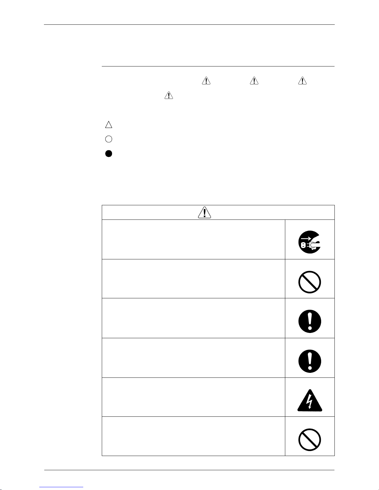
1.1.1 Cautions Regarding Safety of Workers
Warning
Be sure to disconnect the power cable plug from the plug socket before
disassembling the equipment for repair.
Working on the equipment that is connected to the power supply may cause an
electrical shock.
If it is necessary to supply power to the equipment to conduct the repair or
inspecting the circuits, do not touch any electrically charged sections of the
equipment.
If the refrigerant gas is discharged during the repair work, do not touch the
discharged refrigerant gas.
The refrigerant gas may cause frostbite.
When disconnecting the suction or discharge pipe of the compressor at the
welded section, evacuate the refrigerant gas completely at a well-ventilated
place first.
If there is gas remaining inside the compressor, the refrigerant gas or
refrigerating machine oil discharges when the pipe is disconnected, and it may
cause injury.
If the refrigerant gas leaks during the repair work, ventilate the area. The
refrigerant gas may generate toxic gases when it contacts flames.
The step-up capacitor supplies high-voltage electricity to the electrical
components of the outdoor unit.
Be sure to discharge the capacitor completely before conducting repair work.
A charged capacitor may cause an electrical shock.
Do not start or stop the air conditioner operation by plugging or unplugging the
power cable plug.
Plugging or unplugging the power cable plug to operate the equipment may
cause an electrical shock or fire.
SiBE041102_A Introduction
vi
Be sure to wear a safety helmet, gloves, and a safety belt when working at a
high place (more than 2 m). Insufficient safety measures may cause a fall
accident.
In case of R-410A refrigerant models, be sure to use pipes, flare nuts and tools
for the exclusive use of the R-410A refrigerant.
The use of materials for R-22 refrigerant models may cause a serious accident
such as a damage of refrigerant cycle as well as an equipment failure.
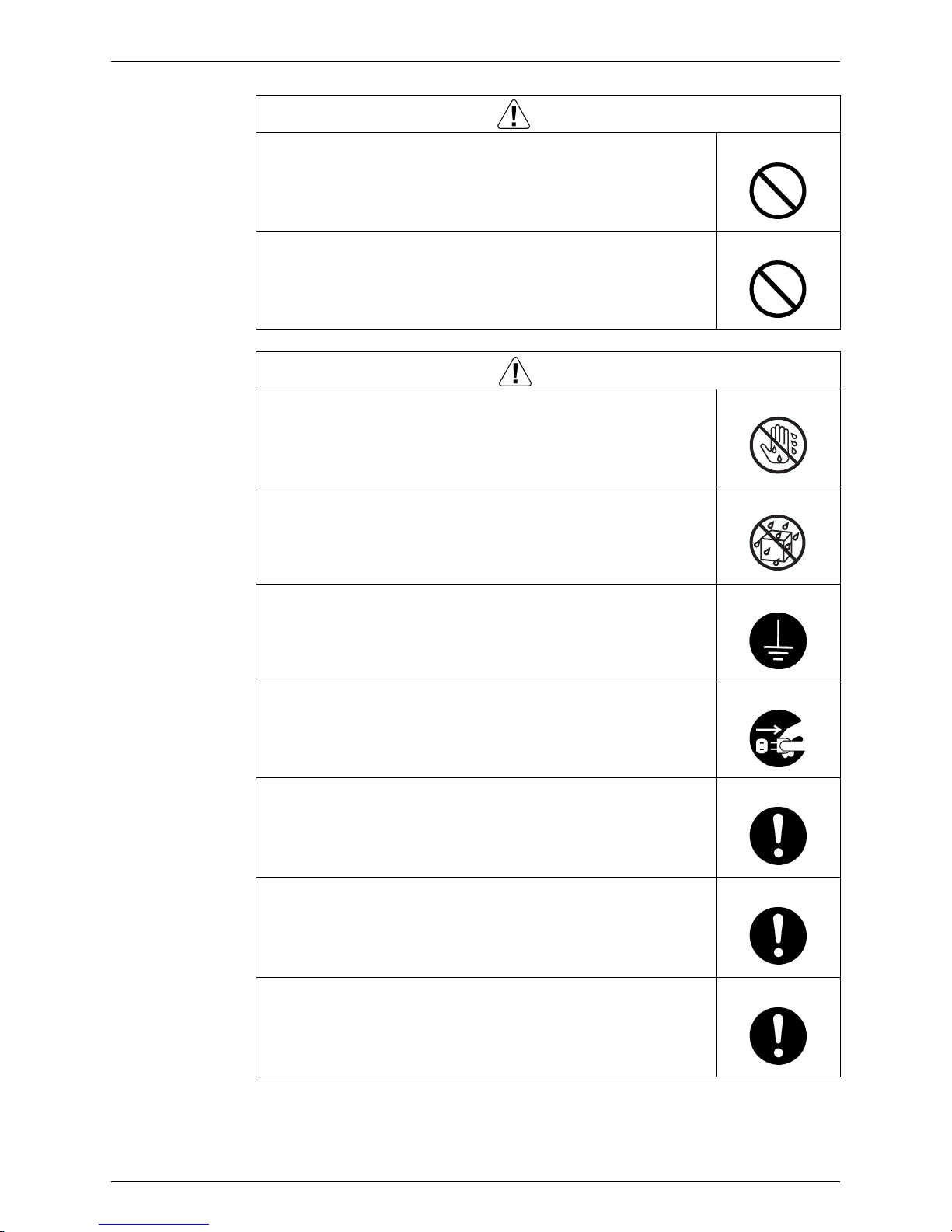
Warning
Caution
Do not repair the electrical components with wet hands.
Working on the equipment with wet hands may cause an electrical shock.
Do not clean the air conditioner by splashing water.
Washing the unit with water may cause an electrical shock.
Be sure to provide the grounding when repairing the equipment in a humid or
wet place, to avoid electrical shocks.
Be sure to turn off the power switch and unplug the power cable when cleaning
the equipment.
The internal fan rotates at a high speed, and may cause injury.
Be sure to conduct repair work with appropriate tools.
The use of inappropriate tools may cause injury.
Be sure to check that the refrigerating cycle section has cooled down enough
before conducting repair work.
Working on the unit when the refrigerating cycle section is hot may cause
burns.
Use the welder in a well-ventilated place.
Using the welder in an enclosed room may cause oxygen deficiency.

Introduction SiBE041102_A
vii
1.1.2 Cautions Regarding Safety of Users
Warning
Be sure to use parts listed in the service parts list of the applicable model and
appropriate tools to conduct repair work. Never attempt to modify the
equipment.
The use of inappropriate parts or tools may cause an electrical shock,
excessive heat generation or fire.
If the power cable and lead wires have scratches or deteriorated, be sure to
replace them.
Damaged cable and wires may cause an electrical shock, excessive heat
generation or fire.
Do not use a joined power cable or extension cable, or share the same power
outlet with other electrical appliances, since it may cause an electrical shock,
excessive heat generation or fire.
Be sure to use an exclusive power circuit for the equipment, and follow the local
technical standards related to the electrical equipment, the internal wiring
regulations, and the instruction manual for installation when conducting
electrical work.
Insufficient power circuit capacity and improper electrical work may cause an
electrical shock or fire.
Be sure to use the specified cable for wiring between the indoor and outdoor
units. Make the connections securely and route the cable properly so that there
is no force pulling the cable at the connection terminals.
Improper connections may cause excessive heat generation or fire.
When wiring between the indoor and outdoor units, make sure that the terminal
cover does not lift off or dismount because of the cable.
If the cover is not mounted properly, the terminal connection section may cause
an electrical shock, excessive heat generation or fire.
Do not damage or modify the power cable.
Damaged or modified power cable may cause an electrical shock or fire.
Placing heavy items on the power cable, and heating or pulling the power cable
may damage the cable.
Do not mix air or gas other than the specified refrigerant (R-410A / R-22) in the
refrigerant system.
If air enters the refrigerating system, an excessively high pressure results,
causing equipment damage and injury.
If the refrigerant gas leaks, be sure to locate the leaking point and repair it
before charging the refrigerant. After charging refrigerant, make sure that there
is no refrigerant leak.
If the leaking point cannot be located and the repair work must be stopped, be
sure to perform pump-down and close the service valve, to prevent the
refrigerant gas from leaking into the room. The refrigerant gas itself is
harmless, but it may generate toxic gases when it contacts flames, such as fan
and other heaters, stoves and ranges.
When relocating the equipment, make sure that the new installation site has
sufficient strength to withstand the weight of the equipment.
If the installation site does not have sufficient strength and if the installation
work is not conducted securely, the equipment may fall and cause injury.
Check to make sure that the power cable plug is not dirty or loose, then insert
the plug into a power outlet securely.
If the plug has dust or loose connection, it may cause an electrical shock or fire.

SiBE041102_A Introduction
viii
Be sure to install the product correctly by using the provided standard
installation frame.
Incorrect use of the installation frame and improper installation may cause the
equipment to fall, resulting in injury.
For unitary type
only
Be sure to install the product securely in the installation frame mounted on the
window frame.
If the unit is not securely mounted, it may fall and cause injury.
For unitary type
only
When replacing the coin battery in the remote controller, be sure to dispose of
the old battery to prevent children from swallowing it.
If a child swallows the coin battery, see a doctor immediately.
Warning
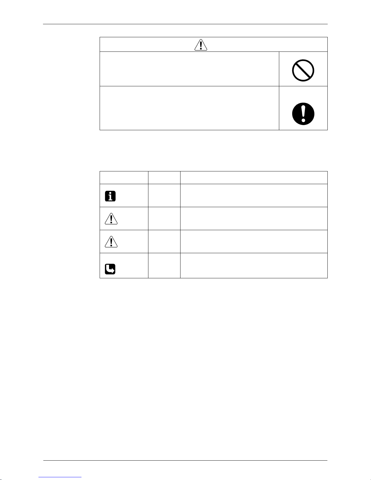
Caution
Installation of a leakage breaker is necessary in some cases depending on the
conditions of the installation site, to prevent electrical shocks.
Do not install the equipment in a place where there is a possibility of
combustible gas leaks.
If the combustible gas leaks and remains around the unit, it may cause a fire.
Check to see if the parts and wires are mounted and connected properly, and
if the connections at the soldered or crimped terminals are secure.
Improper installation and connections may cause excessive heat generation,
fire or an electrical shock.
If the installation platform or frame has corroded, replace it.
Corroded installation platform or frame may cause the unit to fall, resulting in
injury.
Check the grounding, and repair it if the equipment is not properly grounded.
Improper grounding may cause an electrical shock.
Be sure to measure the insulation resistance after the repair, and make sure
that the resistance is 1 MΩ or higher.
Faulty insulation may cause an electrical shock.
Be sure to check the drainage of the indoor unit after the repair.
Faulty drainage may cause the water to enter the room and wet the furniture
and floor.
Introduction SiBE041102_A
ix
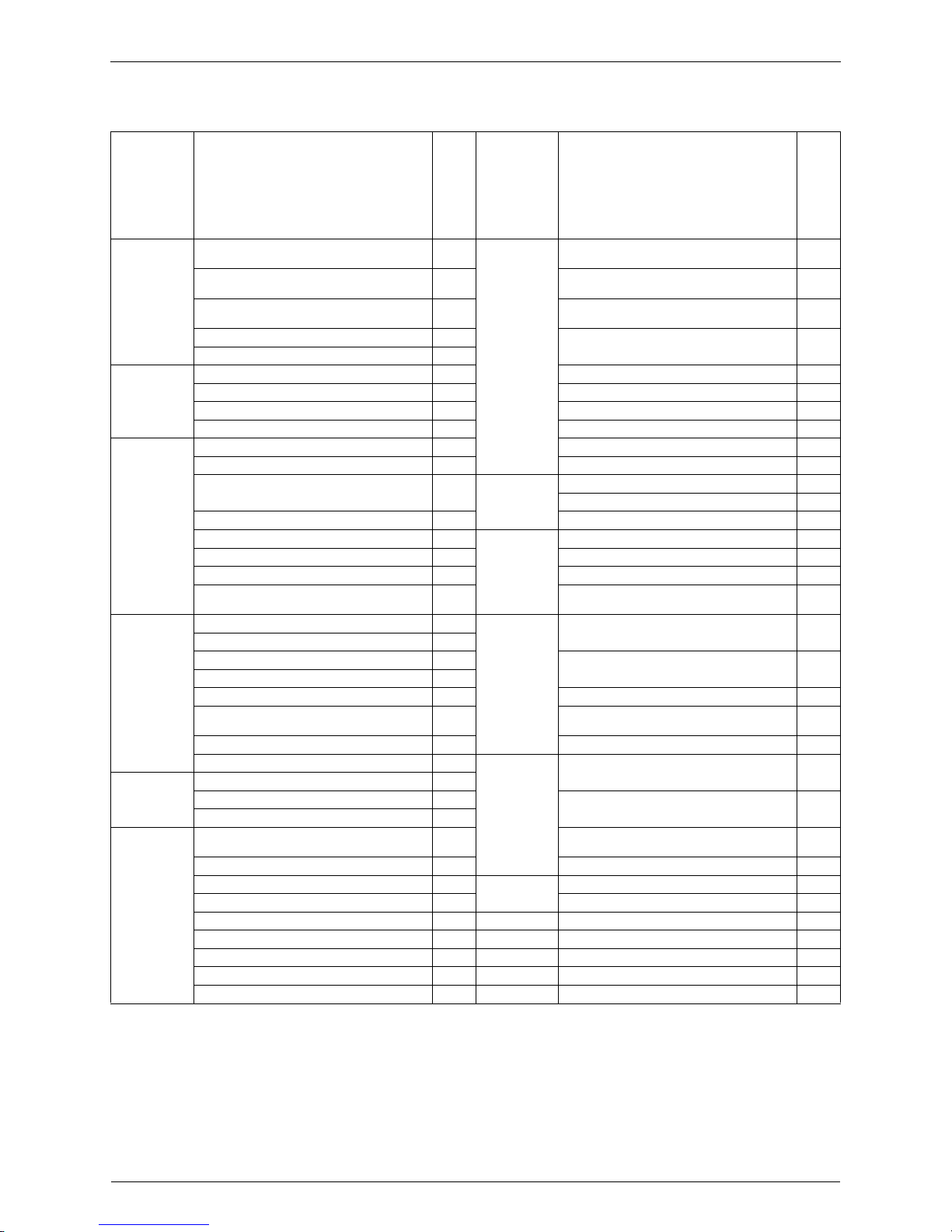
1.2 Used Icons
Icons are used to attract the attention of the reader to specific information. The meaning of each
icon is described in the table below:
Do not tilt the unit when removing it.
The water inside the unit may spill and wet the furniture and floor.
Be sure to install the packing and seal on the installation frame properly.
If the packing and seal are not installed properly, water may enter the room and
wet the furniture and floor.
For unitary type
only
Caution
Icon Type of
Information
Description
Note:
Note A “note” provides information that is not indispensable, but may
nevertheless be valuable to the reader, such as tips and tricks.
Caution
Caution A “caution” is used when there is danger that the reader, through
incorrect manipulation, may damage equipment, loose data, get
an unexpected result or has to restart (part of) a procedure.
Warning
Warning A “warning” is used when there is danger of personal injury.
Reference A “reference” guides the reader to other places in this binder or
in this manual, where he/she will find additional information on a
specific topic.

SiBE041102_A
List of Functions 1
Part 1
List of Functions
1. Functions.................................................................................................2
Functions SiBE041102_A
2 List of Functions
1. Functions
Category Functions
FTXN25/35KEV1B
RXN25/35KEV1B
Category Functions
FTXN25/35KEV1B
RXN25/35KEV1B
Basic
Function
Inverter
(with Inverter Power Control)
z
Health & Clean
Air-Purifying Filter —
Operation Limit for Cooling (°CDB)
10
~ 46
Photocatalytic Deodorizing Filter —
Operation Limit for Heating (°CWB)
–
15
~ 18
Air-Purifying Filter with Photocatalytic
Deodorizing Function
—
PAM Control
z
Titanium Apatite Photocatalytic
Air-Purifying Filter
z
Standby Electricity Saving
z
Compressor Oval Scroll Compressor — Air Filter (Prefilter)
z
Swing Compressor
z
Wipe-Clean Flat Panel
z
Rotary Compressor — Washable Grille —
Reluctance DC Motor
z
MOLD PROOF Operation —
Comfortable
Airflow
Power-Airflow Flap
z
Heating Dry Operation —
Power-Airflow Dual Flaps — Good-Sleep Cooling Operation —
Power-Airflow Diffuser —
Timer 24-Hour ON/OFF TIMER —
Count Up-Down ON/OFF TIMER
z
Wide-Angle Louvers
z
NIGHT SET Mode
z
Vertical Auto-Swing (Up and Down)
z
Worry Free
“Reliability &
Durability”
Auto-Restart (after Power Failure)
z
Horizontal Auto-Swing (Right and Left) — Self-Diagnosis (Digital, LED) Display
z
3-D Airflow — Wiring Error Check Function —
COMFORT AIRFLOW Operation
z
Anti-Corrosion Treatment of Outdoor Heat
Exchanger
z
Comfort
Control
Auto Fan Speed
z
Flexibility
Multi-Split / Split Type Compatible Indoor Unit —
Indoor Unit Quiet Operation
z
NIGHT QUIET Mode (Automatic) —
Flexible Power Supply Correspondence —
OUTDOOR UNIT QUIET Operation (Manual) —
INTELLIGENT EYE Operation — Chargeless 10 m
Quick Warming Function
(Preheating operation)
z
Either Side Drain (Right or Left)
z
Hot-Start Function
z
Power Selection —
Automatic Defrosting
z
Remote
Control
5-Room Centralized Controller (Option) —
Operation Automatic Operation
z
Program Dry Operation
z
Remote Control Adaptor
(Normal Open Pulse Contact) (Option)
—
Fan Only
z
Lifestyle
Convenience
New POWERFUL Operation (Non-Inverter) —
Remote Control Adaptor
(Normal Open Contact) (Option)
—
Inverter POWERFUL Operation
z
DIII-NET Compatible (Adaptor) (Option) —
Priority-Room Setting — Remote
Controller
Wireless
z
COOL / HEAT Mode Lock — Wired (Option)
z
HOME LEAVE Operation —
ECONO Operation
z
Indoor Unit ON/OFF Button
z
Signal Receiving Sign
z
Temperature Display —
Note: z
: Holding Functions
— : No Functions

SiBE041102_A
Specifications 3
Part 2
Specifications
1. Specifications..........................................................................................4

Specifications SiBE041102_A
4 Specifications
1. Specifications
50 Hz, 220 - 230 - 240 V
Note:
The data are based on the conditions shown in the table below.
Model
Indoor Unit FTXN25KEV1B FTXN35KEV1B
Outdoor Unit
RXN25KEV1B RXN35KEV1B
Cooling Heating Cooling Heating
Capacity
Rated (Min. ~ Max.)
kW 2.5 (1.3 ~ 2.8) 2.8 (1.3 ~ 3.5) 3.2 (1.3 ~ 3.5) 3.5 (1.3 ~ 3.7)
Btu/h 8,500 (4,400 ~ 9,600) 9,600 (4,400 ~ 11,900) 10,900 (4,400 - 11,900) 11,900 (4,400 ~ 12,600)
kcal/h 2,150 (1,120 ~ 2,410) 2,410 (1,120 ~ 3,010) 2,750 (1,120 ~ 3,010) 3,010 (1,120 ~ 3,180)
Moisture Removal L/h 1.2
—
1.7
—
Running Current (Rated) A 3.8 - 3.6 - 3.5 3.9 - 3.7 - 3.5 4.9 - 4.7 - 4.5 4.7 - 4.5 - 4.3
Power Consumption
Rated (Min. ~ Max.)
W 795 (310 ~ 1,040) 820 (260 ~ 1,030) 1,060 (310 ~ 1,480) 1,020 (260 ~ 1,200)
Power Factor (Rated) % 95.1 - 96.0 - 94.6 95.6 - 96.4 - 97.6 98.3 - 98.1 - 98.1 98.6 - 98.6 - 98.8
COP
Rated (Min. ~ Max.)
W/W 3.13 (4.19 ~ 2.69) 3.41 (5.00 ~ 3.40) 3.02 (4.19 ~ 2.36) 3.43 (5.00 ~ 3.08)
Piping
Connections
Liquid mm
φ
6.4
φ
6.4
Gas mm
φ
9.5
φ
9.5
Drain mm
φ
16.0
φ
16.0
Heat Insulation Both Liquid and Gas Pipes Both Liquid and Gas Pipes
Max. Interunit Piping Length m 15 15
Max. Interunit Height Difference m 12 12
Chargeless m 10 10
Amount of Additional Charge of
Refrigerant
g/m 20 20
Indoor Unit FTXN25KEV1B FTXN35KEV1B
Front Panel Color White White
Airflow Rate
H
m³/min
(cfm)
9.2 (325) 9.8 (346) 9.6 (339) 10.1 (357)
M 6.9 (244) 7.9 (279) 7.5 (265) 8.3 (293)
L 4.6 (162) 6.0 (212) 5.6 (198) 6.4 (226)
SL 3.9 (138) 5.3 (187) 4.5 (159) 5.7 (201)
Fan
Type Cross Flow Fan Cross Flow Fan
Motor Output W 15 15
Speed Steps 5 Steps, Quiet, Auto 5 Steps, Quiet, Auto
Air Direction Control Right, Left, Horizontal, Downward Right, Left, Horizontal, Downward
Air Filter Removable / Washable / Mildew Proof Removable / Washable / Mildew Proof
Running Current (Rated) A 0.15 - 0.15 - 0.16 0.15 - 0.15 - 0.16 0.15 - 0.15 - 0.16 0.15 - 0.15 - 0.16
Power Consumption (Rated) W 29 29 29 29
Power Factor (Rated) % 84.8 - 84.1 - 75.5 84.8 - 84.1 - 75.5 84.8 - 84.1 - 75.5 84.8 - 84.1 - 75.5
Temperature Control Microcomputer Control Microcomputer Control
Dimensions (H × W × D) mm 283 × 770 × 198 283 × 770 × 198
Packaged Dimensions (H × W × D) mm 261 × 844 × 342 261 × 844 × 342
Weigh t kg 8 8
Gross Weight kg 11 11
Sound
Pressure
Level
H / M / L / SL dB(A) 40 / 33 / 26 / 22 40 / 34 / 28 / 25 41 / 34 / 27 / 23 41 / 35 / 29 / 26
Sound Power Level dB 56 56 57 57
Outdoor Unit RXN25KEV1B RXN35KEV1B
Casing Color Ivory White Ivory White
Compressor
Type Hermetically Sealed Swing Type Hermetically Sealed Swing Type
Model 1YC23AJXD 1YC23AJXD
Motor Output W 600 600
Refrigerant
Oil
Type FVC50K FVC50K
Charge L 0.375 0.375
Refrigerant
Type R-410A R-410A
Charge kg 0.74 0.95
Airflow Rate H
m³/min
(cfm)
28.8 (1,017) 28.8 (1,017) 28.8 (1,017) 28.8 (1,017)
Fan
Type Propeller Propeller
Motor Output W 20 20
Running Current (Rated) A 3.65 - 3.45 - 3.34 3.75 - 3.55 - 3.34 4.75 - 4.55 - 4.34 4.55 - 4.35 - 4.14
Power Consumption (Rated) W 766 791 1,031 991
Power Factor (Rated) % 95.4 - 96.5 - 95.6 95.9 - 96.9 - 98.7 98.7 - 98.5 - 99.0 99.0 - 99.1 - 99.7
Starting Current A 3.9 4.9
Dimensions (H × W × D) mm 550 × 658 × 275 550 × 658 × 275
Packaged Dimensions (H × W × D) mm 592 × 771 × 348 592 × 771 × 348
Weight kg 26 28
Gross Weight kg 30 32
Sound Pressure Level dB(A) 47 48 49 50
Sound Power Level dB 61 62 63 64
Drawing No. 3D071262 3D071263
Conversion Formulae
kcal/h = kW × 860
Btu/h = kW × 3412
cfm = m³/min × 35.3
Cooling Heating Piping Length
Indoor ; 27°CDB / 19°CWB
Outdoor ; 35°CDB / 24°CWB
Indoor ; 20°CDB
Outdoor ; 7°CDB / 6°CWB
5 m

SiBE041102_A
Printed Circuit Board Connector Wiring Diagram 5
Part 3
Printed Circuit Board
Connector Wiring Diagram
1. Indoor Unit...............................................................................................6
2. Outdoor Unit............................................................................................8

Indoor Unit SiBE041102_A
6 Printed Circuit Board Connector Wiring Diagram
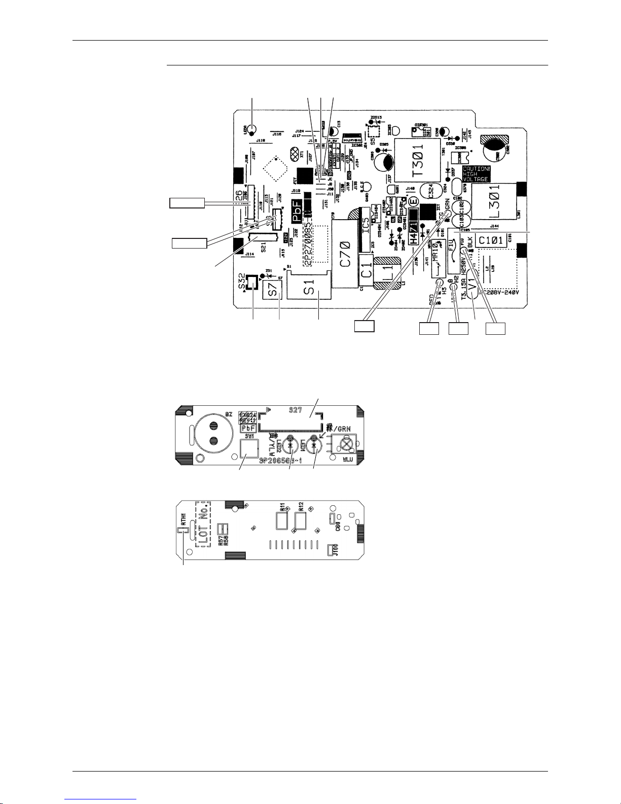
1. Indoor Unit
Connectors and
Other Parts
PCB (1): Control PCB
PCB (2): Display PCB
1) S1, S7 Connector for fan motor
2) S6 Connector for swing motor (horizontal blade)
3) S21 Connector for wired remote controller (option)
4) S26 Connector for display PCB
5) S32 Connector for indoor heat exchanger thermistor
6) H1, H2, H3, FG Connector for terminal board
7) V1 Varistor
8) JA Address setting jumper
JB Fan speed setting when compressor stops for thermostat OFF
JC Power failure recovery function (auto-restart)
∗
Refer to page 140 for detail.
9) LED A LED for service monitor (green)
10)F1U Fuse (3.15 A, 250 V)
1) S27 Connector for control PCB
2) SW1 (S1W) Forced cooling operation ON/OFF button
3) LED1 (H1P) LED for operation (green)
4) LED2 (H2P) LED for timer (yellow)
5) RTH1 (R1T) Room temperature thermistor
SiBE041102_A Indoor Unit
Printed Circuit Board Connector Wiring Diagram 7
PCB Detail PCB (1): Control PCB
PCB (2): Display PCB
LED_A
JB
JC
JA
LED_A
JB
JC
JA
F1U
H1H2H3
FG
S1
V1S7S32
S21
S26
S6
2P270085-1
S27
SW1
(Solder side)
LED2 LED1
RTH1
3P206563-1

Outdoor Unit SiBE041102_A
8 Printed Circuit Board Connector Wiring Diagram
2. Outdoor Unit
Connectors and
Other Parts
PCB Detail
1) S20 Connector for electronic expansion valve coil
2) S40 Connector for overload protector
3) S70 Connector for fan motor
4) S80 Connector for four way valve coil
5) S90 Connector for thermistors
(outdoor temperature, outdoor heat exchanger, discharge pipe)
6) HL1, HN1, S Connector for terminal board
7) E1, E2 Terminal for earth
8) HR1, HR2 Connector for reactor
9) U, V, W Connector for compressor
10)LED A LED for service monitor (green)
11)FU1, FU2 Fuse (3.15 A, 250 V)
12)FU3 Fuse (20 A, 250 V)
13)V2, V3, V150 Varistor
14)J5 Jumper for improvement of defrost performance
∗
Refer to page 140 for detail.
FU3
V3
V2
FU1
E1, E2
HR1
FU2
HR2
U, V, W
J5
S90S40S20S80
S70
V150
S
LED A
HN1
HL1
2P271899-1

SiBE041102_A
Function and Control 9
Part 4
Function and Control
1. Main Functions......................................................................................10
1.1 Temperature Control ..............................................................................10
1.2 Frequency Principle................................................................................10
1.3 Airflow Direction Control.........................................................................12
1.4 Fan Speed Control for Indoor Unit .........................................................13
1.5 Program Dry Operation ..........................................................................14
1.6 Automatic Operation...............................................................................15
1.7 Thermostat Control.................................................................................16
1.8 NIGHT SET Mode ..................................................................................17
1.9 ECONO Operation .................................................................................18
1.10 Inverter POWERFUL Operation .............................................................19
1.11 Other Functions......................................................................................20
2. Function of Thermistor ..........................................................................21
3. Control Specification .............................................................................22
3.1 Mode Hierarchy ......................................................................................22
3.2 Frequency Control..................................................................................23
3.3 Controls at Mode Changing / Start-up....................................................25
3.4 Discharge Pipe Temperature Control.....................................................26
3.5 Input Current Control ..............................................................................27
3.6 Freeze-up Protection Control .................................................................28
3.7 Heating Peak-cut Control .......................................................................28
3.8 Outdoor Fan Control...............................................................................29
3.9 Liquid Compression Protection Function................................................29
3.10 Defrost Control .......................................................................................30
3.11 Electronic Expansion Valve Control .......................................................31
3.12 Malfunctions ...........................................................................................34

Main Functions SiBE041102_A
10 Function and Control
1. Main Functions
1.1 Temperature Control
Definitions of
Temperatures
The definitions of temperatures are classified as following.
Room temperature: temperature of lower part of the room
Set temperature: temperature set by remote controller
Room thermistor temperature: temperature detected by room temperature thermistor
Target temperature: temperature determined by microcomputer
Temperature
Control
The temperature of the room is detected by the room temperature thermistor. However, there is
difference between the “temperature detected by room temperature thermistor” and the
“temperature of lower part of the room”, depending on the type of the indoor unit or installation
condition. Practically, the temperature control is done by the “target temperature appropriately
adjusted for the indoor unit” and the “temperature detected by room temperature thermistor”.
1.2 Frequency Principle
Main Control
Parameters
The compressor is frequency-controlled during normal operation. The target frequency is set by
the following 2 parameters coming from the operating indoor unit:
The load condition of the operating indoor unit
The difference between the room thermistor temperature and the target temperature
Additional
Control
Parameters
The target frequency is adapted by additional parameters in the following cases:
Frequency restrictions
Initial settings
Forced cooling operation
Inverter Principle To regulate the capacity, a frequency control is needed. The inverter makes it possible to vary
the rotation speed of the compressor. The following table explains the conversion principle:
Target temperature
Set temperature
Room temperature
Room thermistor temperature
(R12321)
Phase Description
1 The supplied AC power source is converted into the DC power source for the present.
2 The DC power source is reconverted into the three phase AC power source with variable
frequency.
When the frequency increases, the rotation speed of the compressor increases resulting
in an increased refrigerant circulation. This leads to a higher amount of the heat
exchange per unit.
When the frequency decreases, the rotation speed of the compressor decreases
resulting in a decreased refrigerant circulation. This leads to a lower amount of the heat
exchange per unit.
SiBE041102_A Main Functions
Function and Control 11
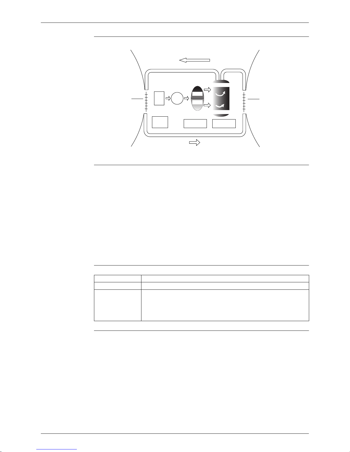
Drawing of
Inverter
The following drawing shows a schematic view of the inverter principle:
Inverter Features The inverter provides the following features:
The regulating capacity can be changed according to the changes in the outdoor
temperature and cooling / heating load.
Quick heating and quick cooling
The compressor rotational speed is increased when starting the heating (or cooling). This
enables to reach the set temperature quickly.
Even during extreme cold weather, high capacity is achieved. It is maintained even when the
outdoor temperature is 2°C.
Comfortable air conditioning
A fine adjustment is integrated to keep the room temperature constant.
Energy saving heating and cooling
Once the set temperature is reached, the energy saving operation enables to maintain the
room temperature at low power.
Frequency Limits The following functions regulate the minimum and maximum frequency:
Forced Cooling
Operation
Refer to page
138
for detail.
Refrigerant circulation rate (high)
high f
low f
freq=variable
Refrigerant circulation rate (low)
high speed
low speed
(R2812)
Amount of heat
exchanged air (large)
freq=
constant
50 Hz
60 Hz
capacity=
variable
Amount of heat
exchanged air (small)
AC
power
DC
power
Amount of heat
exchanged air (large)
Amount of heat
exchanged air (small)
Frequency Functions
Low Four way valve operation compensation. Refer to page 25.
High Compressor protection function. Refer to page 26.
Discharge pipe temperature control. Refer to page 26.
Input current control. Refer to page 27.
Freeze-up protection control. Refer to page 28.
Heating peak-cut control. Refer to page 28.
Defrost control. Refer to page 30.
Main Functions SiBE041102_A
12 Function and Control
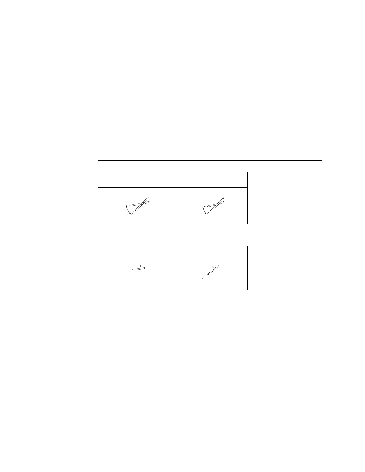
1.3 Airflow Direction Control
Power-Airflow
Flap
The large flap sends a large volume of air downwards to the floor. The flap provides an optimum
control in cooling, dry, and heating mode.
Cooling / Dry Mode
During cooling or dry mode, the flap retracts into the indoor unit. Then, cool air can be blown far
and distributed all over the room.
Heating Mode
During heating mode, the large flap directs airflow downwards to spread the warm air to the
entire room.
Wide-Angle
Louvers
The louvers, made of elastic synthetic resin, provide a wide range of airflow that guarantees a
comfortable air distribution.
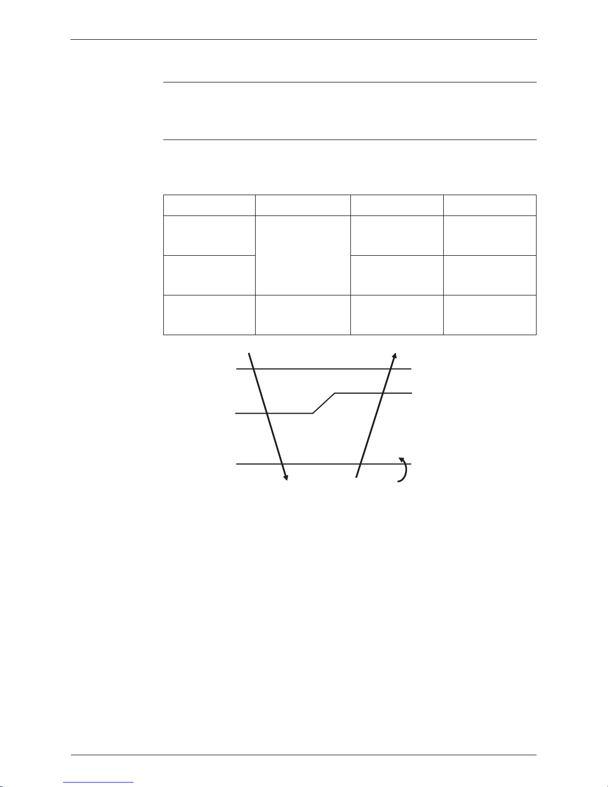
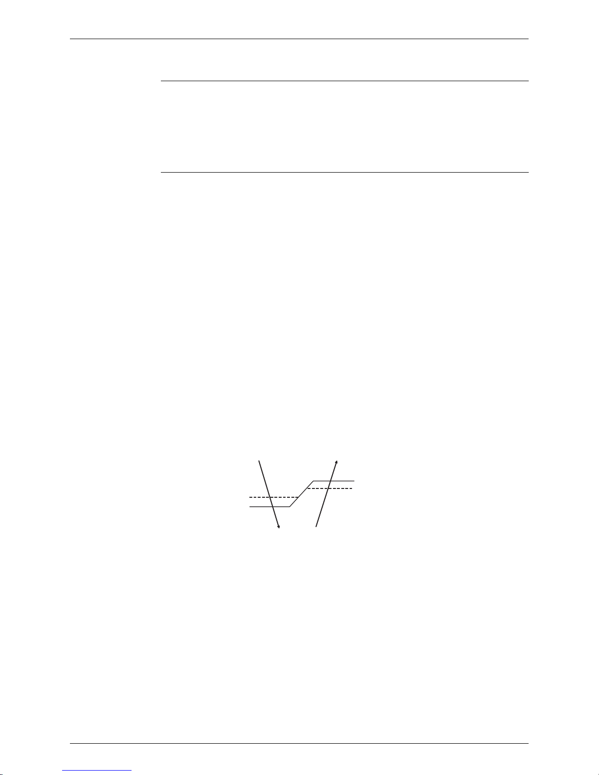
Auto-Swing The following table explains the auto swing process for cooling, dry, fan, and heating:
COMFORT
AIRFLOW
Operation
The vertical swing flap is controlled not to blow the air directly on the person in the room.
Vertical Swing (up and down)
Cooling / Dry / Fan Heating
(R11256)
5˚
45˚
(R11257)
15˚
45˚
Cooling Heating
(R11259)
0˚
(R11258)
50˚
SiBE041102_A Main Functions
Function and Control 13
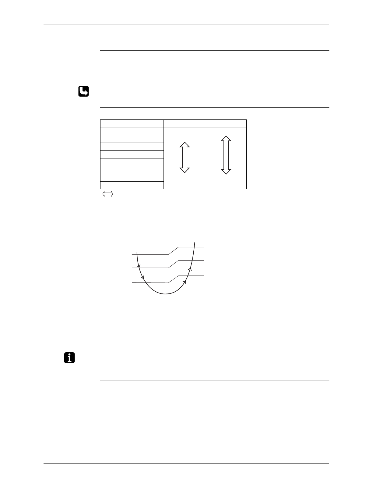
1.4 Fan Speed Control for Indoor Unit
Outline Phase control and fan speed control contains 9 steps: LLL, LL, SL, L, ML, M, MH, H, and HH.
The airflow rate can be automatically controlled depending on the difference between the room
thermistor temperature and the target temperature. This is done through phase control and Hall
IC control.
For more information about Hall IC, refer to the troubleshooting for fan motor on page 57.
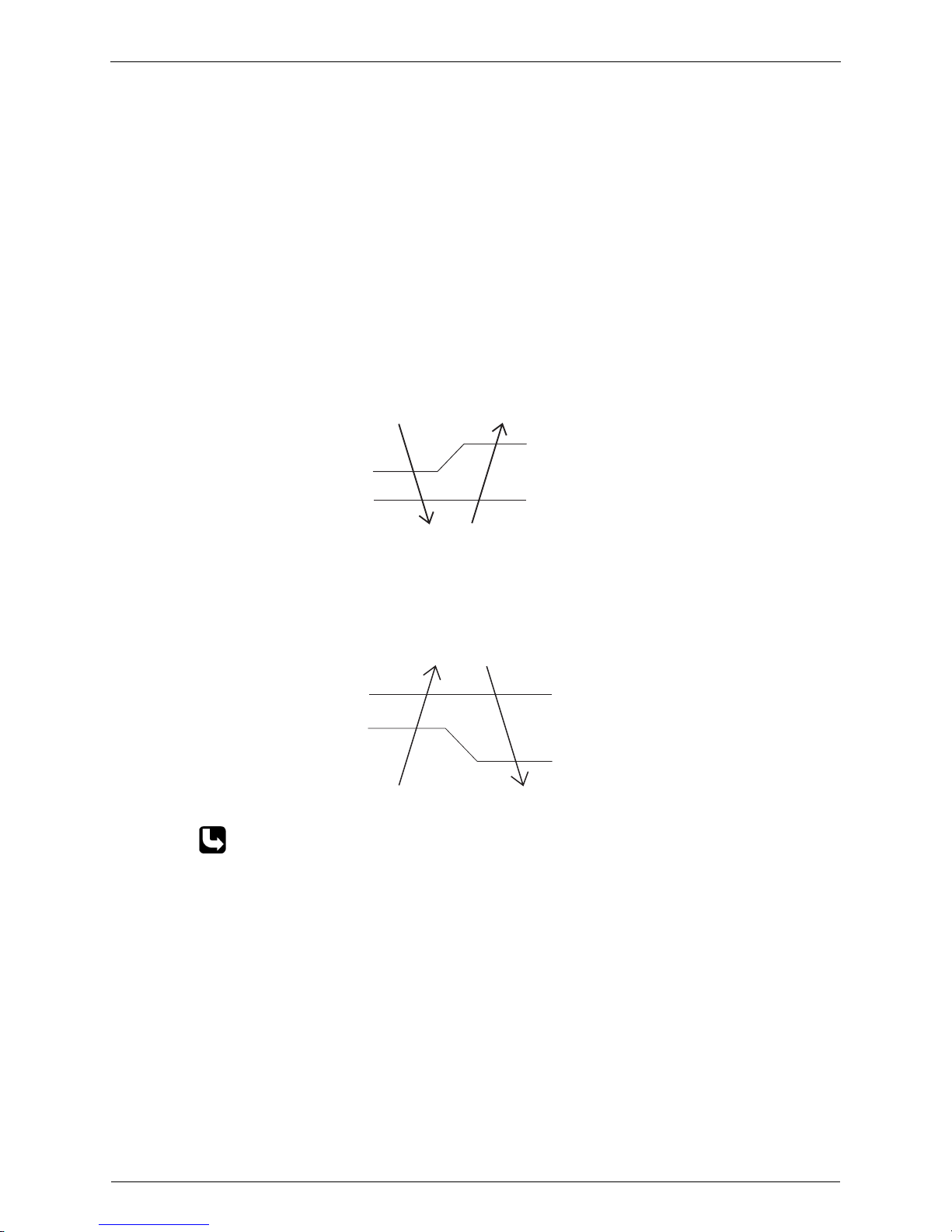
Automatic Fan
Speed Control
In automatic fan speed operation, the step “SL” is not available.
= The airflow rate is automatically controlled within this range when the FAN setting
button is set to automatic
.
<Cooling>
The following drawing explains the principle of fan speed control for cooling.
*In automatic fan speed operation, upper limit is at M tap in 30 minutes from the operation start.
<Heating>
On heating mode, the fan speed is regulated according to the indoor heat exchanger
temperature and the difference between the room thermistor temperature and the target
temperature.
Note: 1. During POWERFUL operation, fan rotates at H tap + 50 rpm.
2. Fan stops during defrost operation.
COMFORT
AIRFLOW
Operation
The fan speed is controlled automatically.
The latest command has the priority between POWERFUL and COMFORT AIRFLOW.
Step Cooling Heating
LLL
LL
L
ML
M
MH
H
HH (POWERFUL)
(R6833)
(R6834)
(R14588)
Fan speed
+2.5°C
+1.5°C
+0.5°C
MH*
M
ML
L
+3°C
+2°C
+1°C
Room thermistor temperature – target temperature
Main Functions SiBE041102_A
14 Function and Control
1.5 Program Dry Operation
Outline Program dry operation removes humidity while preventing the room temperature from lowering.
Since the microcomputer controls both the temperature and airflow rate, the temperature
adjustment and fan adjustment buttons are inoperable in this mode.
Detail The microcomputer automatically sets the temperature and airflow rate. The difference between
the room thermistor temperature at start-up and the target temperature is divided into two
zones. Then, the unit operates in the dry mode with an appropriate capacity for each zone to
maintain the temperature and humidity at a comfortable level.
Room thermistor
temperature at start-up
Target temperatureXThermostat OFF pointYThermostat ON point
Z
24°C or more
Room thermistor
temperature at start-up
X
–
2.5°C
X
–
0.5°C
or
Y + 0.5°C (zone B)
continues for 10 min.
23.5°C
X
–
2.0°C
X
–
0.5°C
or
Y + 0.5°C (zone B)
continues for 10 min.
~
18°C
18°C X
–
2.0°C
X
–
0.5°C = 17.5°C
or
Y + 0.5°C (zone B)
continues for 10 min.
17.5°C
~
Z
X
Y
Zone B
Zone B
Zone A = Thermostat OFF
Zone C = Thermostat ON
+0.5˚C
(R11581)
SiBE041102_A Main Functions
Function and Control 15
1.6 Automatic Operation
Outline Automatic Cooling / Heating Function
When the AUTO mode is selected with the remote controller, the microcomputer automatically
determines the operation mode as cooling or heating according to the room temperature and
the set temperature at start-up, and automatically operates in that mode.
The unit automatically switches the operation mode to maintain the room temperature at the set
temperature.
Detail Ts: set temperature (set by remote controller)
Tt: target temperature (determined by microcomputer)
Tr: room thermistor temperature (detected by room temperature thermistor)
C: correction value
1. The set temperature (Ts) determines the target temperature (Tt).
(Ts = 18 ~ 30°C).
2. The target temperature (Tt) is calculated as;
Tt = Ts + C
where C is the correction value
.
C = 0°C
3. Thermostat ON/OFF point and mode switching point are as follows.
Tr means the room thermistor temperature.
(1) Heating
→
Cooling switching point:
Tr
≥
Tt + 2.5°C
(2) Cooling
→
Heating switching point:
Tr < Tt – 2.5°C
(3) Thermostat ON/OFF point is the same as the ON/OFF point of cooling or heating
operation.
4. During initial operation
Tr
≥
Ts : Cooling operation
Tr < Ts : Heating operation
Ex: When the target temperature is 25°C
Cooling
→
23°C: Thermostat OFF
→
22°C: Switch to heating
Heating
→
26.5°C: Thermostat OFF → 27.5°C: Switch to cooling
(R11893)
Target temperature + 2.5˚C
Heating Operation
Target temperature – 2.5˚C
Cooling Operation
Target temperature – 2.0˚C
= Thermostat OFF
Target temperature + 1.5˚C
= Thermostat OFF
Main Functions SiBE041102_A
16 Function and Control
1.7 Thermostat Control
Thermostat control is based on the difference between the room thermistor temperature and the
target temperature.
Thermostat OFF Condition
The temperature difference is in the zone A.
Thermostat ON Condition
The temperature difference returns to the zone C after being in the zone A.
The system resumes from defrost control in any zones except A.
The operation turns on in any zones except A.
The monitoring time has passed while the temperature difference is in the zone B.
(Cooling / Dry : 10 minutes, Heating : 10 seconds)
<Cooling / Dry>
<Heating>
Refer to “Temperature Control” on page 10 for detail.
B
A
OFF
ON
C
Room thermistor temperature – target temperature
–1.5˚C
(R12319)
Cooling : –0.5˚C
Dry : –0.5˚C
Cooling : –2.0˚C
Dry : –2.5 ~ –2.0˚C
B
B
A
A
OFF
OFF
ON
ON
C
C
1.5˚C
1.0˚C
Room thermistor temperature – target temperature
0˚C
(R12320)
SiBE041102_A Main Functions
Function and Control 17
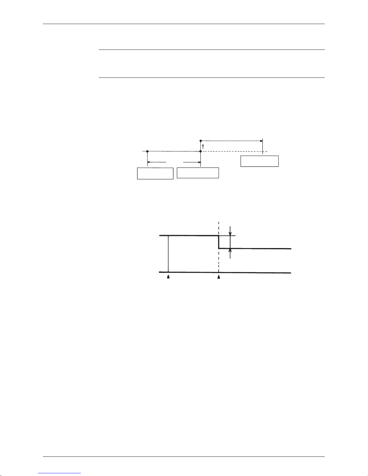
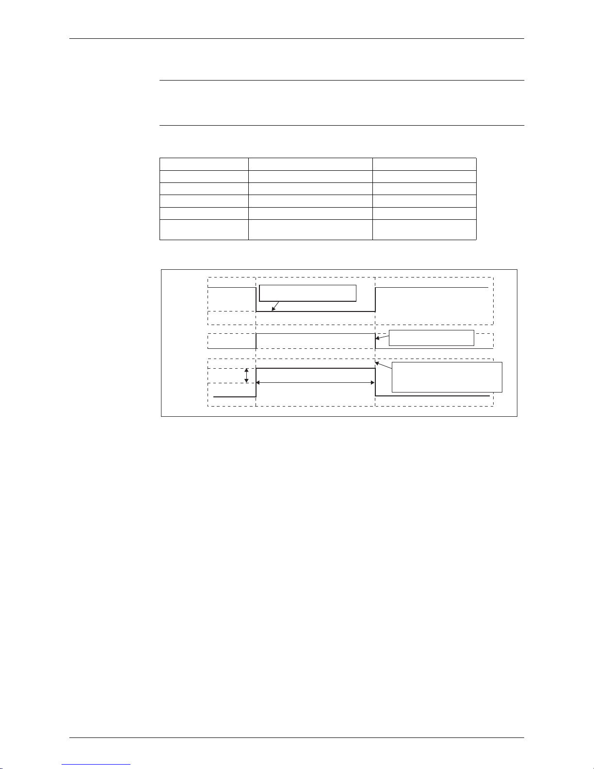
1.8 NIGHT SET Mode
Outline When the OFF timer is set, the NIGHT SET Mode is automatically activated. The NIGHT SET
Mode keeps the airflow rate setting.
Detail The NIGHT SET Mode continues operation at the target temperature for the first one hour, then
automatically raises the target temperature slightly in the case of cooling, or lowers it slightly in
the case of heating. This prevents excessive cooling in summer and excessive heating in winter
to ensure comfortable sleeping conditions, and also conserves electricity.
<Cooling>
<Heating>
(R10870)
TIMER operation
NIGHT SET Mode ON
Target temperature
+0.5˚C
temperature shift
Operation stops
at the set hours
1 hour
0.5˚C
2˚C
(R11813)
Target temperature
1 hour later
TIMER operation
NIGHT SET Mode ON
Main Functions SiBE041102_A
18 Function and Control
1.9 ECONO Operation
The "ECONO operation" reduces the maximum operating current and the power consumption.
This operation is particularly convenient for energy-saving-oriented users. It is also a major
bonus for those whose breaker capacities do not allow the use of multiple electrical devices and
air conditioners.
It is easily activated from the wireless remote controller by pushing the ECONO button.
When this function is activated, the maximum capacity also decreases.
The remote controller can send the ECONO command when the unit is in COOL, HEAT,
DRY, or AUTO operation. This function can only be set when the unit is running. Pressing
the ON/OFF button on the remote controller cancels the function.
This function and POWERFUL operation cannot be used at the same time. The latest
command has the priority.
ECONO Operation
(R9288)
Normal
Maximum during normal operation
Maximum during ECONO operation
Time
Power
consumption
and current
SiBE041102_A Main Functions
Function and Control 19
1.10 Inverter POWERFUL Operation
Outline In order to exploit the cooling and heating capacity to full extent, operate the air conditioner by
increasing the indoor fan rotating speed and the compressor frequency.
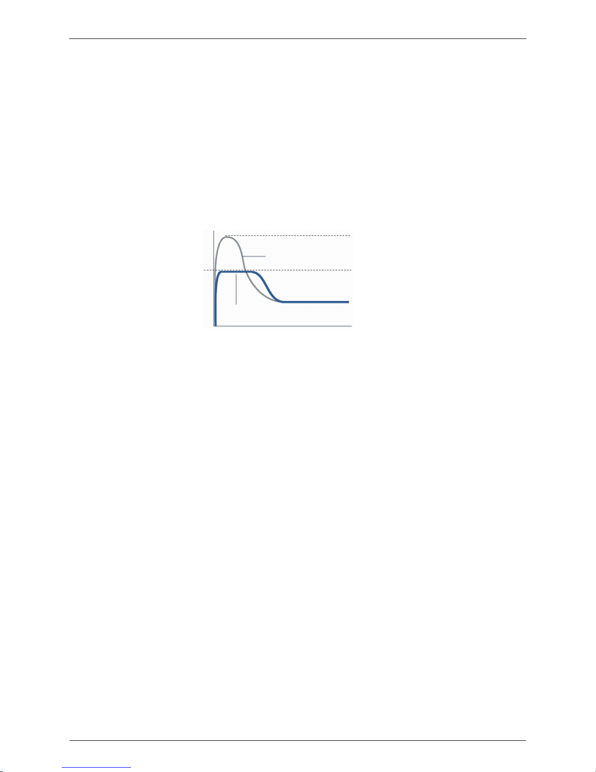
Detail When POWERFUL button is pressed, the fan speed and target temperature are converted to
the following states for 20 minutes.
Ex: POWERFUL operation in cooling mode
Operation mode Fan speed Target temperature
COOL H tap + 50 rpm 18°C
DRY Dry rotating speed + 50 rpm Lowered by 2.5°C
HEAT H tap + 50 rpm 31°C
FAN H tap + 50 rpm —
AUTO Same as cooling / heating in
POWERFUL operation
The target temperature is
kept unchanged.
(R7096)
Target temp.
Fan
50 rpm
18˚C
H tap
Set tap
20 minutes
Ending condition: "or" in 1 to 3
1. After the lapse of 20 minutes.
2. Operation OFF
3. POWERFUL operation is OFF.
It should be the lower limit of
cooling temperature.
It counts 20 minutes. also
in the remote controller.
POWERFUL
ON
POWERFUL
OFF

Main Functions SiBE041102_A
20 Function and Control
1.11 Other Functions
1.11.1 Hot-Start Function
In order to prevent the cold air blast that normally comes when heating operation is started, the
temperature of the indoor heat exchanger is detected, and either the airflow is stopped or is
made very weak thereby carrying out comfortable heating of the room.
∗
The cold air blast is also prevented using a similar control when the defrosting operation is
started or when the thermostat is turned ON.
1.11.2 Signal Receiving Sign
When the indoor unit receives a signal from the remote controller, the unit emits a signal
receiving sound.
1.11.3 Indoor Unit ON/OFF Button
An ON/OFF button is provided on the display of the unit.
Press this button once to start operation. Press once again to stop it.
This button is useful when the remote controller is missing or the battery has run out.
The operation mode refers to the following table.
<Forced cooling operation>
Forced cooling operation can be started by pressing the ON/OFF button for 5 to 9 seconds
while the unit is not operating.
Refer to page
138
for detail.
Note: When the ON/OFF button is pressed for 10 seconds or more, the forced cooling operation is
stopped.
1.11.4 Titanium Apatite Photocatalytic Air-Purifying Filter
This filter combines the Air-Purifying Filter and Titanium Apatite Photocatalytic Deodorizing
Filter as a single highly effective filter. The filter traps microscopic particles, decomposes odors
and even deactivates bacteria and viruses. It lasts for 3 years without replacement if washed
about once every 6 months.
1.11.5 Auto-restart Function
If a power failure (including one for just a moment) occurs during the operation, the operation
restarts automatically when the power is restored in the same condition as before the power
failure.
Note: It takes 3 minutes to restart the operation because the 3-minute standby function is activated.
Mode Temperature setting Airflow rate
AUTO 25°C Automatic
ON/OFF
ON/OFF button
(R14568)
 Loading...