

Daikin FTX12NMVJU, FVXS12NVJU, FVXS15NVJU, RXL09QMVJU, RXL12QMVJU Service Manual
...
Service
Manual
SiUS091601EA
Inverter Pair
Wall Mounted Type FTX-N/U Series
Floor Standing Type FVXS-V Series
Duct Connected Type FDMQ-R Series
[Applied Models]
Inverter Pair : Heat Pump

SiUS091601EA
Introduction .......................................................................................1
1. Safety Cautions...........................................................................................2
1.1 Warnings and Cautions Regarding Safety of Workers................................. 2
1.2 Warnings and Cautions Regarding Safety of Users..................................... 4
2. Icons Used ..................................................................................................7
3. Revision History ..........................................................................................8
Part 1 General Information ...............................................................9
1. Applicable Models .....................................................................................10
2. Functions...................................................................................................11
Part 2 Specifications....................................................................... 13
1. Specifications ............................................................................................14
Part 3 Printed Circuit Board Connector Wiring Diagram................ 21
1. Indoor Unit.................................................................................................22
1.1 FTX09/12NMVJU ....................................................................................... 22
1.2 FTX15NMVJU ............................................................................................ 24
1.3 FTX18/24UVJU .......................................................................................... 26
1.4 FVXS09/12/15NVJU................................................................................... 28
1.5 FDMQ12/18/24RVJU ................................................................................. 30
2. Wireless Remote Controller Receiver .......................................................32
2.1 BRC082A43 ............................................................................................... 32
3. Wired Remote Controller...........................................................................33
3.1 BRC1E73 ................................................................................................... 33
4. Outdoor Unit..............................................................................................34
4.1 RXL09QMVJU............................................................................................ 34
4.2 RXL12QMVJU(9) ....................................................................................... 36
4.3 RXL15QMVJU............................................................................................ 38
4.4 RXL18/24UMVJU ....................................................................................... 39
5. Optional Adaptor .......................................................................................42
5.1 BRP072A43 Wireless LAN Adaptor ........................................................... 42
5.2 KRP067A41/KRP980B2 Remote Control PC-board Set............................ 42
Part 4 Functions and Control .......................................................... 43
1. Common Functions ...................................................................................44
1.1 Temperature Control .................................................................................. 44
1.2 Frequency Principle.................................................................................... 44
2. Functions for FTX, FVXS Series ...............................................................46
2.1 Airflow Direction Control............................................................................. 46
2.2 COMFORT AIRFLOW Operation ............................................................... 49
2.3 Fan Speed Control for Indoor Unit ............................................................. 50
2.4 Program Dry Operation .............................................................................. 51
2.5 Automatic Cooling/Heating Changeover .................................................... 52
i Table of Contents

SiUS091601EA
2.6 Thermostat Control..................................................................................... 53
2.7 NIGHT SET Mode ...................................................................................... 54
2.8 ECONO Operation .................................................................................... 55
2.9 INTELLIGENT EYE Operation ................................................................... 56
2.10 POWERFUL Operation .............................................................................. 57
2.11 Clock Setting .............................................................................................. 58
2.12 WEEKLY TIMER Operation ....................................................................... 59
2.13 Other Functions.......................................................................................... 65
3. Functions for FDMQ Series.......................................................................66
3.1 Fan Speed Control for Indoor Unit ............................................................. 66
3.2 Program Dry Operation .............................................................................. 67
3.3 Clock and Calender Setting (With BRC1E73) ............................................ 68
3.4 Schedule Timer Operation (With BRC1E73).............................................. 70
3.5 Drain Pump Control.................................................................................... 73
3.6 Hot Start Control (In Heating Operation Only)............................................ 75
3.7 Other Functions.......................................................................................... 76
4. Thermistor Functions ................................................................................77
5. Control Specification .................................................................................78
5.1 Mode Hierarchy .......................................................................................... 78
5.2 Frequency Control...................................................................................... 78
5.3 Controls at Mode Changing/Start-up.......................................................... 80
5.4 Discharge Pipe Temperature Control......................................................... 82
5.5 Input Current Control.................................................................................. 83
5.6 Freeze-up Protection Control ..................................................................... 84
5.7 Heating Peak-cut Control ........................................................................... 84
5.8 Outdoor Fan Control................................................................................... 85
5.9 Liquid Compression Protection Function.................................................... 85
5.10 Defrost Control ........................................................................................... 86
5.11 Electronic Expansion Valve Control ........................................................... 87
5.12 Malfunctions ............................................................................................... 90
Part 5 Remote Controller ................................................................91
1. Applicable Remote Controller ...................................................................92
2. ARC466A21 ..............................................................................................93
3. ARC466A37 ..............................................................................................95
4. ARC480A8 ................................................................................................97
5. BRC082A43 ..............................................................................................98
6. BRC1E73 ................................................................................................ 100
Part 6 Service Diagnosis ............................................................... 106
1. General Problem Symptoms and Check Items .......................................108
2. Troubleshooting with LED .......................................................................109
2.1 Indoor Unit................................................................................................ 109
2.2 Outdoor Unit ............................................................................................. 110
3. Service Diagnosis ................................................................................... 111
3.1 ARC480 Series......................................................................................... 111
Table of Contents ii

SiUS091601EA
3.2 ARC466 Series......................................................................................... 114
3.3 BRC1E73 ................................................................................................. 117
3.4 BRC082A43 ............................................................................................. 119
4. Error Codes and Description...................................................................123
5. Troubleshooting for FTX, FVXS Series...................................................124
5.1 Indoor Unit PCB Abnormality ................................................................... 124
5.2 Freeze-up Protection Control/Heating Peak-cut Control .......................... 126
5.3 Indoor Fan Motor (DC Motor) or Related Abnormality ............................. 128
5.4 Thermistor or Related Abnormality........................................................... 132
5.5 Low-voltage Detection or Over-voltage Detection.................................... 133
5.6 Signal Transmission Error (Between Indoor Unit and Outdoor Unit)........ 135
5.7 Unspecified Voltage (Between Indoor Unit and Outdoor Unit) ................. 137
6. Troubleshooting for FDMQ Series ..........................................................138
6.1 Indoor Unit PCB Abnormality ................................................................... 138
6.2 Drain Level Control System Abnormality.................................................. 139
6.3 Indoor Fan Motor (DC Motor) or Related Abnormality ............................. 140
6.4 Indoor Fan PCB Abnormality.................................................................... 142
6.5 Humidifier or Related Abnormality............................................................ 143
6.6 Thermistor or Related Abnormality........................................................... 144
6.7 Remote Controller Thermistor Abnormality .............................................. 145
6.8 Low-voltage Detection or Over-voltage Detection.................................... 146
6.9 Signal Transmission Error (Between Indoor and Outdoor Unit) ............... 148
6.10 Signal Transmission Error (Between Indoor Unit and Remote Controller)
................................................................................................................. 150
6.11 Signal Transmission Error (Between MAIN/SUB Remote Controllers) .... 151
6.12 Mismatching of Indoor Unit and Outdoor Unit .......................................... 152
7. Troubleshooting for Outdoor Unit............................................................153
7.1 Outdoor Unit PCB Abnormality................................................................. 153
7.2 OL Activation (Compressor Overload) ..................................................... 154
7.3 Compressor Lock ..................................................................................... 157
7.4 DC Fan Lock ............................................................................................ 158
7.5 Input Overcurrent Detection ..................................................................... 159
7.6 Four Way Valve Abnormality.................................................................... 161
7.7 Discharge Pipe Temperature Control....................................................... 163
7.8 High Pressure Control in Cooling ............................................................. 165
7.9 System Shutdown due to Temperature Abnormality in the Compressor
................................................................................................................. 167
7.10 Compressor Sensor System Abnormality ................................................ 168
7.11 Position Sensor Abnormality .................................................................... 169
7.12 Thermistor or Related Abnormality (Outdoor Unit)................................... 172
7.13 Electrical Box Temperature Rise.............................................................. 174
7.14 Radiation Fin Temperature Rise .............................................................. 176
7.15 Output Overcurrent Detection .................................................................. 178
7.16 Signal Transmission Error on Outdoor Unit PCB ..................................... 180
8. Check ......................................................................................................181
8.1 Thermistor Resistance Check .................................................................. 181
8.2 Indoor Fan Motor Connector Check......................................................... 182
8.3 Power Supply Waveform Check............................................................... 184
iii Table of Contents

SiUS091601EA
8.4 Electronic Expansion Valve Check........................................................... 184
8.5 Four Way Valve Performance Check ....................................................... 185
8.6 Inverter Unit Refrigerant System Check................................................... 185
8.7 Inverter Analyzer Check........................................................................... 186
8.8 Rotation Pulse Check on the Outdoor Unit PCB ...................................... 189
8.9 Installation Condition Check..................................................................... 190
8.10 Discharge Pressure Check....................................................................... 190
8.11 Outdoor Fan System Check ..................................................................... 191
8.12 Main Circuit Short Check.......................................................................... 191
8.13 Power Module Check ............................................................................... 194
Part 7 Trial Operation and Field Settings ..................................... 197
1. Pump Down Operation............................................................................198
2. Forced Cooling Operation .......................................................................199
3. Trial Operation ........................................................................................202
4. Field Settings for FTX, FVXS Series.......................................................206
4.1 Temperature Display Switch .................................................................... 206
4.2 When 2 Units are Installed in 1 Room...................................................... 207
4.3 Jumper and Switch Settings..................................................................... 209
5. Field Settings for FDMQ Series ..............................................................210
5.1 How to Change the Field Settings............................................................ 210
5.2 Overview of Field Settings........................................................................ 213
5.3 MAIN/SUB and Address Setting for Wireless Remote Controller ............ 214
6. Field Settings for Outdoor Unit................................................................217
6.1 Facility Setting (cooling at low outdoor temperature) ............................... 217
6.2 Drain Pan Heater...................................................................................... 218
7. Silicone Grease on Power Transistor/Diode Bridge................................ 219
Part 8 Appendix ............................................................................. 220
1. Piping Diagrams......................................................................................221
1.1 Indoor Unit................................................................................................ 221
1.2 Outdoor Unit ............................................................................................. 223
2. Wiring Diagrams......................................................................................226
2.1 Indoor Unit................................................................................................ 226
2.2 Outdoor Unit ............................................................................................. 231
3. Operation Limit........................................................................................236
Table of Contents iv

SiUS091601EA
Introduction
1. Safety Cautions...........................................................................................2
1.1 Warnings and Cautions Regarding Safety of Workers................................. 2
1.2 Warnings and Cautions Regarding Safety of Users..................................... 4
2. Icons Used ..................................................................................................7
3. Revision History ..........................................................................................8
1 Introduction
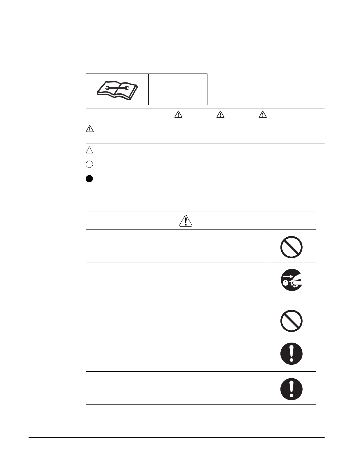
SiUS091601EA Safety Cautions
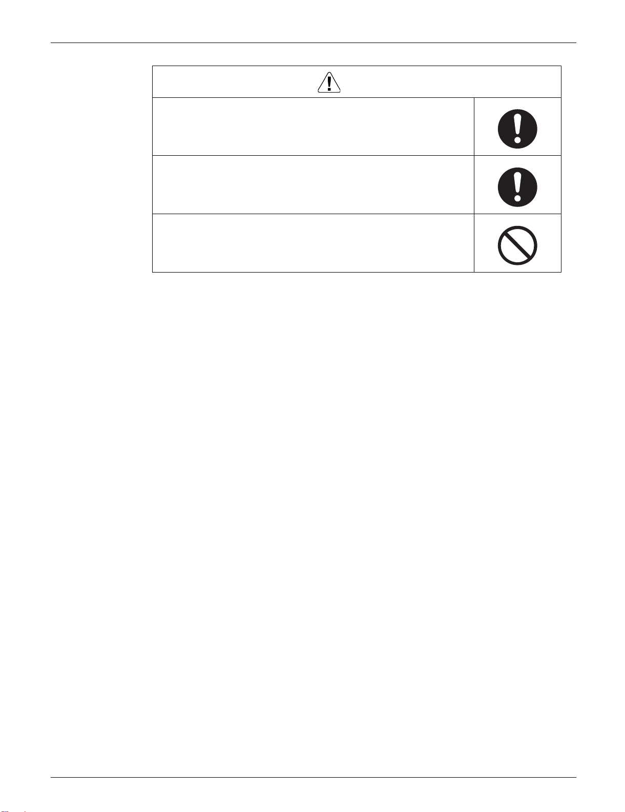
Warning
1. Safety Cautions
Be sure to read the following safety cautions before conducting repair work.
After the repair work is complete, be sure to conduct a test operation to ensure that the equipment
operates normally, and explain the cautions for operating the product to the customer.
This manual is for the
person in charge of
maintenance and
inspection.
Caution Items The caution items are classified into Warning and Caution. The Warning items are
especially important since death or serious injury can result if they are not followed closely. The
Caution items can also lead to serious accidents under some conditions if they are not
followed. Therefore, be sure to observe all the safety caution items described below.
Pictograms This symbol indicates an item for which caution must be exercised.
The pictogram shows the item to which attention must be paid.
This symbol indicates a prohibited action.
The prohibited item or action is shown in the illustration or near the symbol.
This symbol indicates an action that must be taken, or an instruction.
The instruction is shown in the illustration or near the symbol.
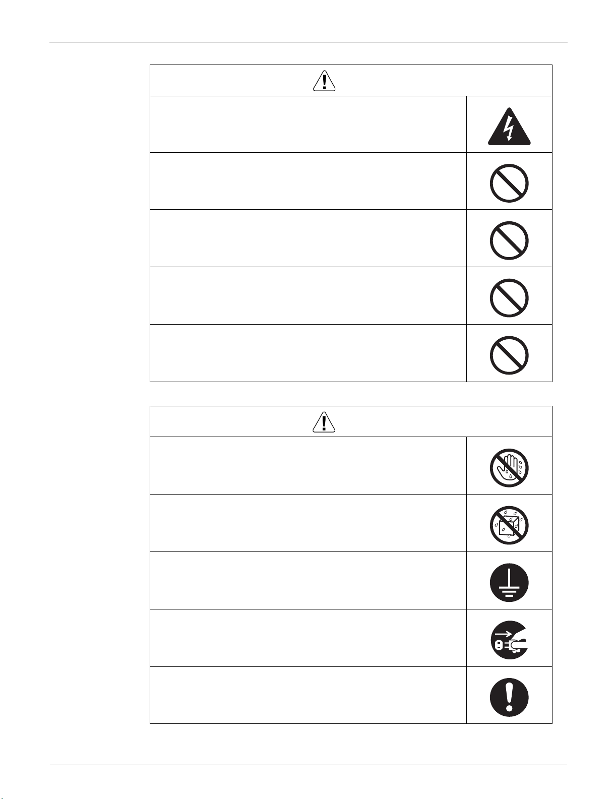
1.1 Warnings and Cautions Regarding Safety of Workers
Do not store equipment in a room with fire sources (e.g., naked
flames, gas appliances, electric heaters).
Be sure to disconnect the power cable from the socket before
disassembling equipment for repair.
Working on equipment that is connected to the power supply may cause
an electrical shock.
If it is necessary to supply power to the equipment to conduct the repair or
inspect the circuits, do not touch any electrically charged sections of the
equipment.
If refrigerant gas is discharged during repair work, do not touch the
discharged refrigerant gas.
Refrigerant gas may cause frostbite.
When disconnecting the suction or discharge pipe of the
compressor at the welded section, evacuate the refrigerant gas
completely at a well-ventilated place first.
If there is gas remaining inside the compressor, the refrigerant gas or
refrigerating machine oil discharges when the pipe is disconnected, and it
may cause injury.
If refrigerant gas leaks during repair work, ventilate the area.
Refrigerant gas may generate toxic gases when it contacts flames.
Introduction 2
Safety Cautions SiUS091601EA
Caution
Warning
Be sure to discharge the capacitor completely before conducting
repair work.
The step-up capacitor supplies high-voltage electricity to the electrical
components of the outdoor unit.
A charged capacitor may cause an electrical shock.
Do not turn the air conditioner on or off by plugging in or
unplugging the power cable.
Plugging in or unplugging the power cable to operate the equipment may
cause an electrical shock or fire.
Be sure to wear a safety helmet, gloves, and a safety belt when
working in a high place (more than 2 m (6.5 ft)).
Insufficient safety measures may cause a fall.
In case of R-32 / R-410A refrigerant models, be sure to use pipes,
flare nuts and tools intended for the exclusive use with the R-32 /
R-410A refrigerant.
The use of materials for R-22 refrigerant models may cause a serious
accident, such as a damage of refrigerant cycle or equipment failure.
Do not mix air or gas other than the specified refrigerant (R-32 /
R-410A / R-22) in the refrigerant system.
If air enters the refrigerant system, an excessively high pressure results,
causing equipment damage and injury.
Do not repair electrical components with wet hands.
Working on the equipment with wet hands may cause an electrical shock.
Do not clean the air conditioner with water.
Washing the unit with water may cause an electrical shock.
Be sure to provide an earth / grounding when repairing the
equipment in a humid or wet place, to avoid electrical shocks.
Be sure to turn off the power switch and unplug the power cable
when cleaning the equipment.
The internal fan rotates at a high speed, and may cause injury.
Be sure to conduct repair work with appropriate tools.
The use of inappropriate tools may cause injury.
3 Introduction
SiUS091601EA Safety Cautions
Caution
Warning
Be sure to check that the refrigerating cycle section has cooled
down enough before conducting repair work.
Working on the unit when the refrigerating cycle section is hot may cause
burns.
Conduct welding work in a well-ventilated place.
Using the welder in an enclosed room may cause oxygen deficiency.
1.2 Warnings and Cautions Regarding Safety of Users
Do not store the equipment in a room with fire sources (e.g., naked
flames, gas appliances, electric heaters).
Be sure to use parts listed in the service parts list of the applicable
model and appropriate tools to conduct repair work. Never attempt
to modify the equipment.
The use of inappropriate parts or tools may cause an electrical shock,
excessive heat generation or fire.
If the power cable and lead wires are scratched or have deteriorated,
be sure to replace them.
Damaged cable and wires may cause an electrical shock, excessive heat
generation or fire.
Do not use a joined power cable or extension cable, or share the
same power outlet with other electrical appliances, since it may
cause an electrical shock, excessive heat generation or fire.
Be sure to use an exclusive power circuit for the equipment, and
follow the local technical standards related to the electrical
equipment, the internal wiring regulations, and the instruction
manual for installation when conducting electrical work.
Insufficient power circuit capacity and improper electrical work may cause
an electrical shock or fire.
Be sure to use the specified cable for wiring between the indoor and
outdoor units.
Make the connections securely and route the cable properly so that there
is no force pulling the cable at the connection terminals.
Improper connections may cause excessive heat generation or fire.
When wiring between the indoor and outdoor units, make sure that
the terminal cover does not lift off or dismount because of the cable.
If the cover is not mounted properly, the terminal connection section may
cause an electrical shock, excessive heat generation or fire.
Do not damage or modify the power cable.
Damaged or modified power cables may cause an electrical shock or fire.
Placing heavy items on the power cable, or heating or pulling the power
cable may damage it.
Introduction 4
Safety Cautions SiUS091601EA
Caution
Warning
Do not mix air or gas other than the specified refrigerant (R-32 /
R-410A / R-22) in the refrigerant system.
If air enters the refrigerant system, an excessively high pressure results,
causing equipment damage and injury.
If the refrigerant gas leaks, be sure to locate the leaking point and
repair it before charging the refrigerant. After charging the
refrigerant, make sure that there is no leak.
If the leaking point cannot be located and the repair work must be
stopped, be sure to pump-down, and close the service valve, to prevent
refrigerant gas from leaking into the room. Refrigerant gas itself is
harmless, but it may generate toxic gases when it contacts flames, such
as those from fan type and other heaters, stoves and ranges.
When relocating the equipment, make sure that the new installation
site has sufficient strength to withstand the weight of the
equipment.
If the installation site does not have sufficient strength or the installation
work is not conducted securely, the equipment may fall and cause injury.
Check to make sure that the power cable plug is not dirty or loose,
then insert the plug into a power outlet securely.
If the plug is dusty or has a loose connection, it may cause an electrical
shock or fire.
When replacing the coin battery in the remote controller, be sure to
dispose of the old battery to prevent children from swallowing it.
If a child swallows the coin battery, see a doctor immediately.
Installation of a leakage breaker is necessary in some cases
depending on the conditions of the installation site, to prevent
electrical shocks.
Do not install the equipment in a place where there is a possibility of
combustible gas leaks.
If combustible gas leaks and remains around the unit, it may cause a fire.
Check to see if parts and wires are mounted and connected
properly, and if connections at the soldered or crimped terminals
are secure.
Improper installation and connections may cause excessive heat
generation, fire or an electrical shock.
If the installation platform or frame has corroded, replace it.
A corroded installation platform or frame may cause the unit to fall,
resulting in injury.
Check the earth / grounding, and repair it if the equipment is not
properly earthed / grounded.
Improper earth / grounding may cause an electrical shock.
5 Introduction
SiUS091601EA Safety Cautions
Caution
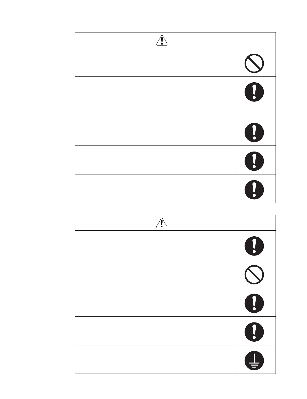
Be sure to measure insulation resistance after the repair, and make
sure that the resistance is 1 M or higher.
Faulty insulation may cause an electrical shock.
Be sure to check the drainage of the indoor unit after the repair.
Faulty drainage may cause water to enter the room and wet the furniture
and floor.
Do not tilt the unit when removing it.
The water inside the unit may spill and wet the furniture and floor.
Introduction 6
Icons Used SiUS091601EA
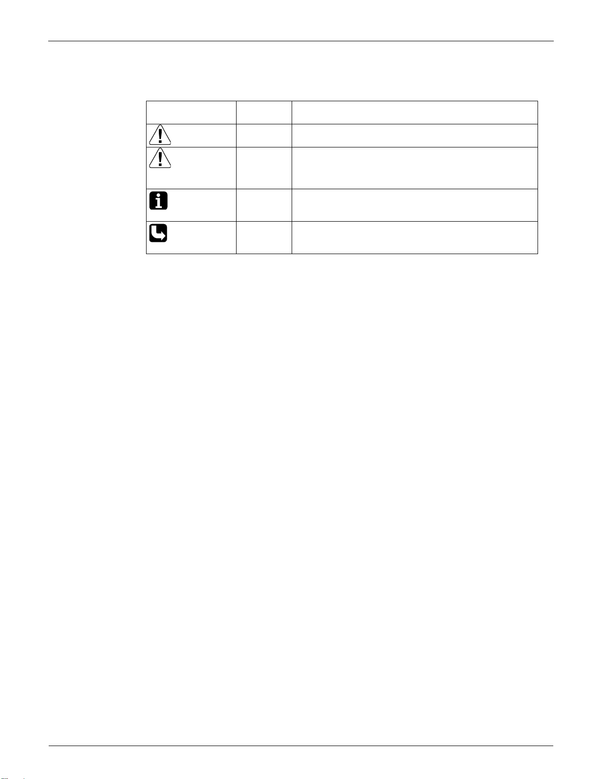
2. Icons Used
The following icons are used to attract the attention of the reader to specific information.
Icon Type of
Information
Warning Warning is used when there is danger of personal injury.
Warning
Caution Caution is used when there is danger that the reader,
Caution
Note Note provides information that is not indispensable, but
Note
Reference Reference guides the reader to other places in this binder
Reference
Description
through incorrect manipulation, may damage equipment,
lose data, get an unexpected result or have to restart (part
of) a procedure.
may nevertheless be valuable to the reader, such as tips
and tricks.
or in this manual, where he/she will find additional
information on a specific topic.
7 Introduction
SiUS091601EA Revision History
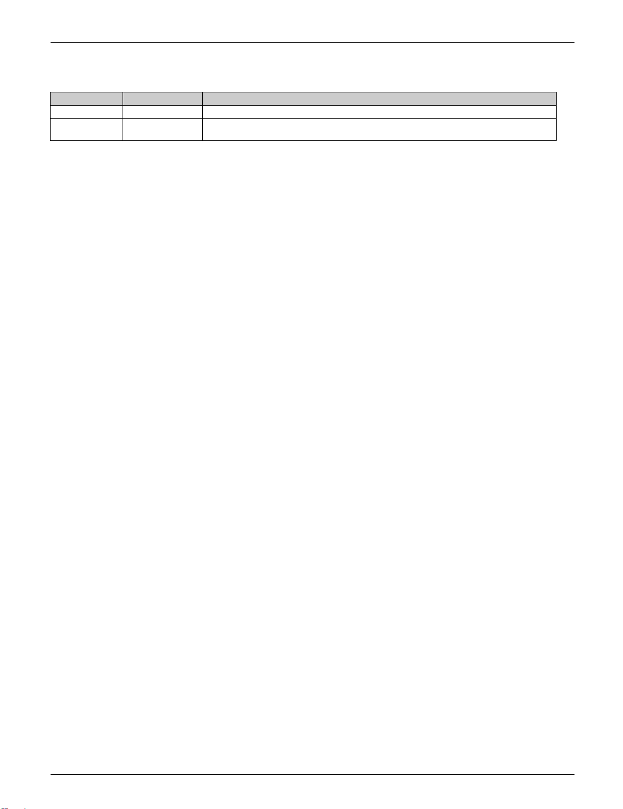
3. Revision History
Month/Year Version Revised contents
02 / 2016 SiUS091601E First edition
10 / 2019 SiUS091601EA
Model addition :
FTX18/24UVJU, FDMQ12/18/24RVJU, RXL12QMVJU9, RXL18/24UMVJU
Introduction 8

SiUS091601EA
Part 1
General Information
1. Applicable Models .....................................................................................10
2. Functions...................................................................................................11
9 Part 1 General Information

SiUS091601EA Applicable Models
1. Applicable Models
Indoor Unit
FTX09NMVJU
FTX12NMVJU
FTX15NMVJU
FTX18UVJU
FTX24UVJU
Outdoor Unit
RXL09QMVJU
RXL12QMVJU
RXL12QMVJU9
RXL15QMVJU
RXL18UMVJU
RXL24UMVJU
FVXS09NVJU
FVXS12NVJU
FVXS15NVJU
FDMQ12RVJU
FDMQ18RVJU
FDMQ24RVJU
Part 1 General Information 10
Functions SiUS091601EA
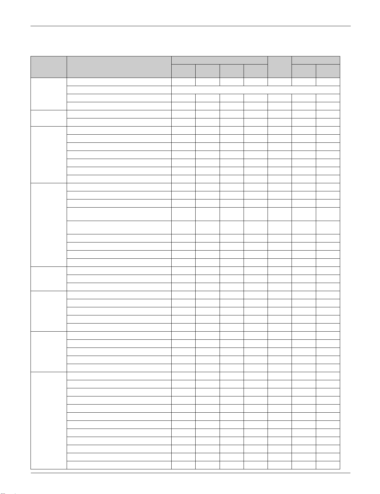
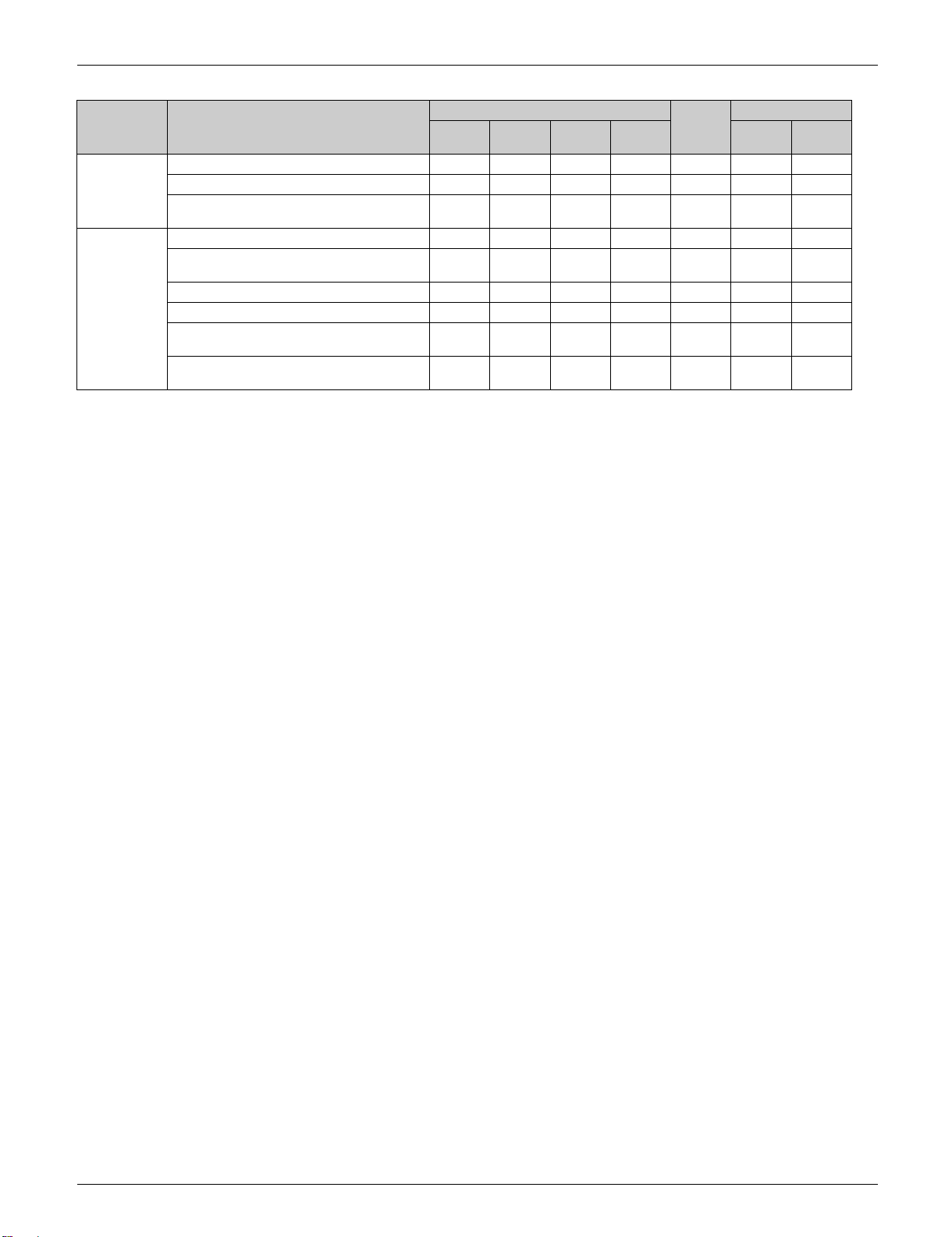
2. Functions
Category Functions FTX
09 12 15 18/24
Basic
Function
Compressor Swing compressor
Comfortable
Airflow
Comfort
Control
Operation Automatic cooling/heating changeover
Lifestyle
Convenience
Health and
Cleanliness
Remote
Control &
Timer
Inverter (with inverter power control)
Operation limit Refer to page 236
PAM control
Standby electricity saving 1 ————
Reluctance DC motor
Power-airflow flap (horizontal blade) —— ——
Power-airflow dual flaps (horizontal blades) — — ———
Wide-angle louvers (vertical blades) ——
Auto-swing (up and down) ——
Auto-swing (right and left) — — — ———
3-D airflow — — — ———
COMFORT AIRFLOW operation ———
Auto fan speed —
Switchable fan speed 5 steps 5 steps 5 steps 5 steps 5 steps 3 steps 3 steps
Indoor unit quiet operation ——
OUTDOOR UNIT QUIET operation
(manual)
INTELLIGENT EYE operation
(auto energy saving)
2 selectable temperature sensors ————— —
Quick warming function —
Hot-start function
Automatic defrosting
Program dry operation
Fan only
Inverter POWERFUL operation ——
ECONO operation ——
Indoor unit ON/OFF switch ——
Emergency operation switch — —————
Signal receiving sign —
Titanium apatite deodorizing filter ——
Air filter (prefilter) ——
Wipe-clean flat panel ——
Silver ion anti-bacterial drain pan —————
Filter cleaning indicator —————
WEEKLY TIMER operation — — — ——
Schedule timer ————— —
24-hour ON/OFF TIMER — — — —
72-hour ON/OFF TIMER — —————
Count up-down ON/OFF timer ———
Off timer (turns unit off after set time) ————— —
Setpoint auto reset ————— —
Setpoint range set ————— —
NIGHT SET mode ——
Remote controller with back light —
DIII-NET compatible (adaptor) Option Option Option Option Option Option Option
Wireless LAN connection Option Option Option Option Option — —
—————
——— ———
FVXS
Wired
R/C
FDMQ
Wireless
R/C
2
11 Part 1 General Information
SiUS091601EA Functions
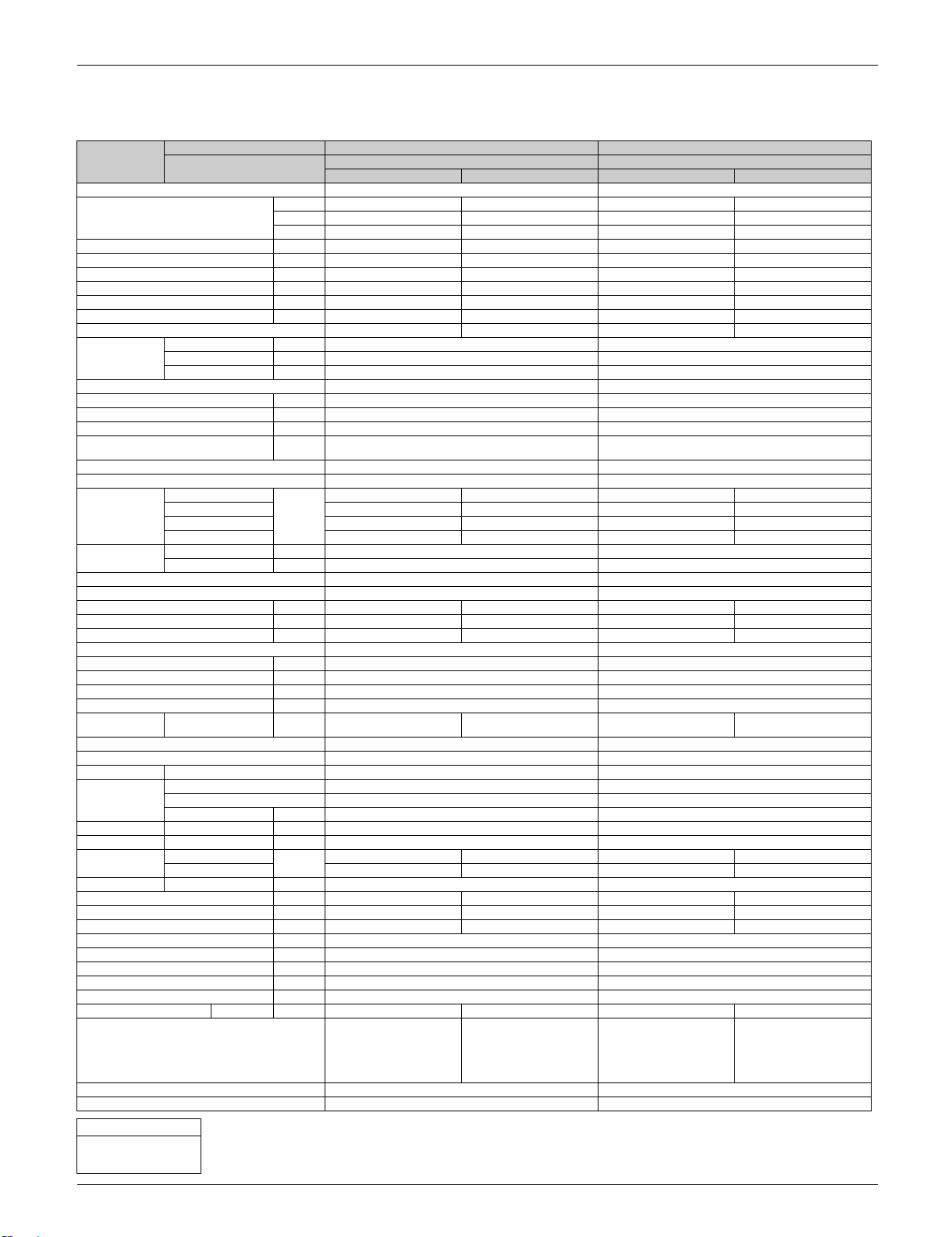
Category Functions FTX
09 12 15 18/24
Worry Free
(Reliability &
Durability)
Work &
Servicing
: Available 1: Not available with RXL12QMVJU9
— : Not available 2: Receiving sound only
Auto-restart (after power failure)
Self-diagnosis (R/C, LED)
Anti-corrosion treatment of outdoor heat
exchanger
Multi-split/split type compatible indoor unit — — — —
Chargeless 32.8 ft.
Drain pump —————
Either side drain (right or left) ———
Low temperature cooling operation –4°F 3
°F/°C changeover R/C temperature display
(factory setting: °F)
3: Below 50°F (10°C):
(10m)
(–20°C)
Below 14°F (–10°C):
32.8 ft.
(10m)
–4°F 3
(–20°C)
32.8 ft.
(10m)
–4°F 3
(–20°C)
Needs setting on outdoor unit.
09/12/15 class cutting jumper on the main PCB
18/24 class switch on the service monitor PCB
Need to install the air direction adjustment grille.
32.8 ft.
(10m)
–4°F 3
(–20°C)
FVXS
32.8 ft.
(10m)
–4°F 3
(–20°C)
FDMQ
Wired
R/C
32.8 ft.
(10m)
–4°F 3
(–20°C)
Wireless
R/C
32.8 ft.
(10m)
–4°F 3
(–20°C)
—
(°F only)
Part 1 General Information 12

SiUS091601EA
Part 2
Specifications
1. Specifications ............................................................................................14
13 Part 2 Specifications
SiUS091601EA Specifications
1. Specifications
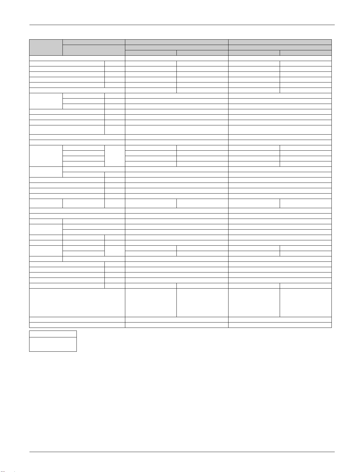
Model Indoor Unit FTX09NMVJU FTX12NMVJU
Power Supply 1 , 60 Hz, 208 - 230 V 1 , 60 Hz, 208 - 230 V
Capacity Rated (Min. ~ Max.) kW 2.64 (1.30 ~ 3.20) 3.20 (1.30 ~ 4.70) 3.20 (1.30 ~ 3.90) 4.00 (1.30 ~ 5.50)
Moisture Removal gal/h 0.32 — 0.45 —
Running Current (Rated) A 3.76 - 3.40 3.95 - 3.57 4.36 - 3.94 5.10 - 4.61
Power Consumption Rated (Min. ~ Max.) W 720 (250 ~ 1,180) 760 (230 ~ 1,440) 870 (280 ~ 1,390) 1,025 (240 ~ 1,660)
Power Factor (Rated) % 92.1 - 92.1 92.6 - 92.6 96.0 - 96.0 96.7 - 96.7
COP Rated (Min. ~ Max.) W/W 3.66 (5.20 ~ 2.70) 4.20 (5.64 ~ 3.26) 3.68 (4.64 ~ 2.80) 3.90 (5.42 ~ 3.30)
EER Rated (Min. ~ Max.) Btu/h·W 12.5 (17.6 ~ 9.2) 14.3 (19.1 ~ 11.1) 12.5 (15.7 ~ 9.6) 13.3 (18.3 ~ 11.3)
SEER / HSPF 20.0 12.5 20.0 12.0
Piping
Connections
Heat Insulation Both Liquid and Gas Pipes Both Liquid and Gas Pipes
Max. Interunit Piping Length ft (m) 65-5/8 (20) 65-5/8 (20)
Max. Interunit Height Difference ft (m) 49-1/4 (15) 49-1/4 (15)
Chargeless ft (m) 32-13/16 (10) 32-13/16 (10)
Amount of Additional Charge of
Refrigerant
Indoor Unit FTX09NMVJU FTX12NMVJU
Front Panel Color White White
Airflow Rate H
Fan Type / Motor Output W Cross Flow Fan / 21 Cross Flow Fan / 28
Air Direction Control Right, Left, Horizontal, Downward Right, Left, Horizontal, Downward
Air Filter Removable, Washable, Mildew Proof Removable, Washable, Mildew Proof
Running Current (Rated) A 0.25 - 0.23 0.23 - 0.21 0.28 - 0.25 0.25 - 0.23
Power Consumption (Rated) W 28 - 28 25 - 25 31 - 31 28 - 28
Power Factor (Rated) % 53.8 - 52.9 52.3 - 51.8 53.2 - 53.9 53.8 - 52.9
Temperature Control Microcomputer Control Microcomputer Control
Dimensions (H × W × D) in. (mm) 11-1/4 × 30-5/16 × 8-3/4 (285 × 770 × 223) 11-1/4 × 30-5/16 × 8-3/4 (285 × 770 × 223)
Packaged Dimensions (H × W × D) in. (mm) 14-3/16 × 32-11/16 × 12 (360 × 831 × 305) 14-3/16 × 32-11/16 × 12 (360 × 831 × 305)
Weight (Mass) Lbs (kg) 18 (8) 18 (8)
Gross Weight (Gross Mass) Lbs (kg) 24 (11) 25 (12)
Sound Pressure
Level
Outdoor Unit RXL09QMVJU RXL12QMVJU
Casing Color Ivory White Ivory White
Heat Exchanger Fin / Spec. Tube Waffle Fin (PE) / 7 mm Hi-XD Tube Waffle Fin (PE) / 7 mm Hi-XD Tube
Compressor Type Hermetically Sealed Swing Type Hermetically Sealed Swing Type
Refrigerant Oil Type / Charge oz (L) FVC50K / 12.4 (0.375) FVC50K / 21.5 (0.650)
Refrigerant Type / Charge Lbs (kg) R-410A / 2.09 (0.95) R-410A / 2.09 (0.95)
Airflow Rate H
Fan Type / Motor Output W Propeller / 18 Propeller / 20
Running Current (Rated) A 3.51 - 3.17 3.72 - 3.36 4.08 - 3.69 4.85 - 4.38
Power Consumption (Rated) W 692 - 692 735 - 735 839 - 839 997 - 997
Power Factor (Rated) % 94.8 - 94.9 95.1 - 95.1 98.9 - 98.9 98.9 - 99.0
Starting Current A 3.95 4.94
Dimensions (H × W × D) in. (mm) 21-5/8 × 26-9/16 × 11-3/16 (550 × 675 × 284) 21-5/8 × 26-9/16 × 11-3/16 (550 × 675 × 284)
Packaged Dimensions (H × W × D) in. (mm) 24-3/4 × 32-11/16 × 16 (629 × 830 × 407) 24-3/4 × 32-11/16 × 16 (629 × 830 × 407)
Weight (Mass) Lbs (kg) 60 (27) 70 (32)
Gross Weight (Gross Mass) Lbs (kg) 71 (32) 80 (36)
Sound Pressure Level H dB(A) 49 49 50 50
Conditions Based on
Drawing No. C: 3D101720 C: 3D101721
Notes SL: The quiet fan level of the airflow rate setting. SL: The quiet fan level of the airflow rate setting.
Conversion Formulae
kcal/h = kW × 860
Btu/h = kW × 3412
cfm = m³/min × 35.3
Outdoor Unit RXL09QMVJU RXL12QMVJU
Btu/h 9,000 (4,400 ~ 10,900) 10,900 (4,400 ~ 16,000) 10,900 (4,400 ~ 13,300) 13,600 (4,400 ~ 18,800)
kcal/h 2,270 (1,120 ~ 2,750) 2,750 (1,120 ~ 4,040) 2,750 (1,120 ~ 3,350) 3,440 (1,120 ~ 4,730)
Liquid in. (mm) 1/4 ( 6.4) 1/4 ( 6.4)
Gas in. (mm) 3/8 ( 9.5) 3/8 ( 9.5)
Drain in. (mm) 5/8 ( 16.0) 5/8 ( 16.0)
oz/ft
(g/m)
M 297 (8.4) 328 (9.3) 311 (8.8) 321 (9.1)
L 244 (6.9) 251 (7.1) 247 (7.0) 258 (7.3)
SL 141 (4.0) 215 (6.1) 145 (4.1) 219 (6.2)
Speed Steps 5 Steps, Quiet, Auto 5 Steps, Quiet, Auto
H / M / L / SL
Model 1YC23AUXD 2YC36PXD
Motor Output W 790 1,100
SL 865 (24.5) 777 (22.0) 865 (24.5) 777 (22.0)
cfm
(m³/min)
dB(A) 43 / 36 / 30 / 19 43 / 36 / 29 / 25 45 / 37 / 30 / 19 45 / 37 / 30 / 26
cfm
(m³/min)
Cooling Heating Cooling Heating
0.21 (20) 0.21 (20)
417 (11.8) 403 (11.4) 434 (12.3) 413 (11.7)
1,105 (31.3) 922 (26.1) 1,144 (32.4) 1,006 (28.5)
Indoor ; 80°FDB (26.7°CDB)
/ 67°FWB (19.4°CWB)
Outdoor ; 95°FDB (35°CDB)
/ 75°FWB (24°CWB)
Piping Length: 25 ft (7.5 m)
Indoor ; 70°FDB (21°CDB) /
60°FWB (15.6°CWB)
Outdoor ; 47°FDB
(8.3°CDB) / 43°FWB
(6°CWB)
Piping Length: 25 ft (7.5 m)
Indoor ; 80°FDB (26.7°CDB)
/ 67°FWB (19.4°CWB)
Outdoor ; 95°FDB (35°CDB)
/ 75°FWB (24°CWB)
Piping Length: 25 ft (7.5 m)
Indoor ; 70°FDB (21°CDB) /
Piping Length: 25 ft (7.5 m)
60°FWB (15.6°CWB)
Outdoor ; 47°FDB
(8.3°CDB) / 43°FWB
(6°CWB)
Part 2 Specifications 14

Specifications SiUS091601EA
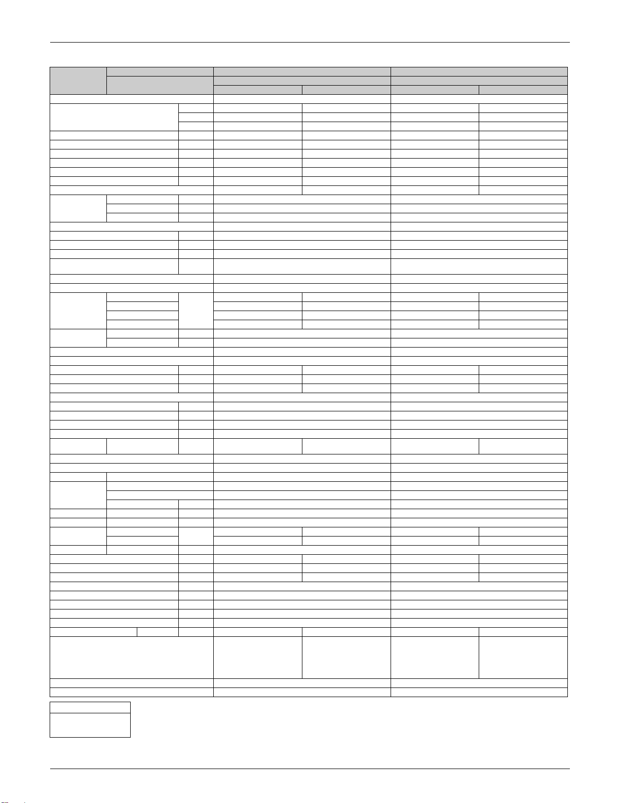
Model Indoor Unit FTX12NMVJU FTX15NMVJU
Power Supply 1 , 60 Hz, 208 - 230 V 1 , 60 Hz, 208 - 230 V
Capacity Rated (Min. ~ Max.) kW 3.20 (1.30 ~ 3.90) 4.00 (1.30 ~ 5.50) 4.40 (1.70 ~ 5.40) 5.35 (1.70 ~ 7.20)
Moisture Removal gal/h 0.45 — 0.63 —
Running Current (Rated) A 4.36 - 3.94 5.10 - 4.61 5.92 - 5.35 6.81 - 6.16
Power Consumption Rated (Min. ~ Max.) W 870 (280 ~ 1,390) 1,025 (240 ~ 1,660) 1,150 (290 ~ 1,630) 1,340 (390 ~ 2,310)
Power Factor (Rated) % 96.0 - 96.0 96.7 - 96.7 93.5 - 93.5 94.6 - 94.6
COP Rated (Min. ~ Max.) W/W 3.68 (4.64 ~ 2.80) 3.90 (5.42 ~ 3.30) 3.82 (5.86 ~ 3.30) 4.00 (4.36 ~ 3.12)
EER Rated (Min. ~ Max.) Btu/h·W 12.5 (15.7 ~ 9.6) 13.3 (18.3 ~ 11.3) 13 (20 ~ 11.3) 13.7 (14.9 ~ 10.6)
SEER / HSPF 20.0 12.0 20.0 13.0
Piping
Connections
Heat Insulation Both Liquid and Gas Pipes Both Liquid and Gas Pipes
Max. Interunit Piping Length ft (m) 65-5/8 (20) 98-1/2 (30)
Max. Interunit Height Difference ft (m) 49-1/4 (15) 65-5/8 (20)
Chargeless ft (m) 32-13/16 (10) 32-13/16 (10)
Amount of Additional Charge of
Refrigerant
Indoor Unit FTX12NMVJU FTX15NMVJU
Front Panel Color White White
Airflow Rate H
Fan Type / Motor Output W Cross Flow Fan / 28 Cross Flow Fan / 33
Air Direction Control Right, Left, Horizontal, Downward Right, Left, Horizontal, Downward
Air Filter Removable, Washable, Mildew Proof Removable, Washable, Mildew Proof
Running Current (Rated) A 0.28 - 0.25 0.25 - 0.23 0.23 - 0.21 0.25 - 0.23
Power Consumption (Rated) W 31 - 31 28 - 28 33 - 33 38 - 38
Power Factor (Rated) % 53.2 - 53.9 53.8 - 52.9 69.0 - 68.3 73.1 - 71.8
Temperature Control Microcomputer Control Microcomputer Control
Dimensions (H × W × D) in. (mm) 11-1/4 × 30-5/16 × 8-3/4 (285 × 770 × 223) 11-5/8 × 39 × 10-3/8 (295 × 990 × 263)
Packaged Dimensions (H × W × D) in. (mm) 14-3/16 × 32-11/16 × 12 (360 × 831 × 305) 14-9/16 × 42-1/2 × 15-3/8 (370 × 1,080 × 390)
Weight (Mass) Lbs (kg) 18 (8) 27 (12)
Gross Weight (Gross Mass) Lbs (kg) 25 (12) 37 (17)
Sound Pressure
Level
Outdoor Unit RXL12QMVJU9 RXL15QMVJU
Casing Color Ivory White Ivory White
Heat Exchanger Fin / Spec. Tube Waffle Fin (PE) / 7 mm Hi-XD Tube Waffle Fin (PE) / 7 mm Hi-XD Tube
Compressor Type Hermetically Sealed Swing Type Hermetically Sealed Swing Type
Refrigerant Oil Type / Charge oz (L) FVC50K / 21.5 (0.650) FVC50K / 21.5 (0.650)
Refrigerant Type / Charge Lbs (kg) R-410A / 2.09 (0.95) R-410A / 3.20 (1.45)
Airflow Rate H
Fan Type / Motor Output W Propeller / 20 Propeller / 71
Running Current (Rated) A 4.08 - 3.69 4.85 - 4.38 5.69 - 5.14 6.56 - 5.93
Power Consumption (Rated) W 839 - 839 997 - 997 1,117 - 1,117 1,302 - 1,302
Power Factor (Rated) % 98.9 - 98.9 98.9 - 99.0 94.4 - 94.5 95.4 - 95.5
Starting Current A 4.94 6.81
Dimensions (H × W × D) in. (mm) 21-5/8 × 26-9/16 × 11-3/16 (550 × 675 × 284) 28-15/16 × 34-1/4 × 12-5/8 (735 × 870 × 320)
Packaged Dimensions (H × W × D) in. (mm) 24-3/4 × 32-11/16 × 16 (629 × 830 × 407) 31-7/8 × 41-9/16 × 18-1/4 (810 × 1,056 × 464)
Weight (Mass) Lbs (kg) 70 (32) 108 (49)
Gross Weight (Gross Mass) Lbs (kg) 80 (36) 123 (56)
Sound Pressure Level H dB(A) 50 50 50 55
Conditions Based on Indoor ; 80°FDB
Drawing No. C: 3D123801 C: 3D101716
Notes SL: The quiet fan level of the airflow rate setting. SL: The quiet fan level of the airflow rate setting.
Conversion Formulae
kcal/h = kW × 860
Btu/h = kW × 3412
cfm = m³/min × 35.3
Outdoor Unit RXL12QMVJU9 RXL15QMVJU
Btu/h 10,900 (4,400 ~ 13,300) 13,600 (4,400 ~ 18,800) 15,000 (5,800 ~ 18,400) 18,300 (5,800 ~ 24,600)
kcal/h 2,750 (1,120 ~ 3,350) 3,440 (1,120 ~ 4,730) 3,780 (1,460 ~ 4,640) 4,600 (1,460 ~ 6,190)
Liquid in. (mm) 1/4 ( 6.4) 1/4 ( 6.4)
Gas in. (mm) 3/8 ( 9.5) 1/2 ( 12.7)
Drain in. (mm) 5/8 ( 16.0) 5/8 ( 16.0)
oz/ft
(g/m)
M 311 (8.8) 321 (9.1) 505 (14.3) 554 (15.7)
L 247 (7.0) 258 (7.3) 431 (12.2) 470 (13.3)
SL 145 (4.1) 219 (6.2) 367 (10.4) 399 (11.3)
Speed Steps 5 Steps, Quiet, Auto 5 Steps, Quiet, Auto
H / M / L / SL
Model 2YC36PXD 2YC36PXD
Motor Output W 1,100 1,100
SL 865 (24.5) 777 (22.0) 1,762 (49.9) 1,585 (44.9)
cfm
(m³/min)
dB(A) 45 / 37 / 30 / 19 45 / 37 / 30 / 26 45 / 41 / 36 / 33 45 / 41 / 37 / 33
cfm
(m³/min)
Cooling Heating Cooling Heating
0.21 (20) 0.21 (20)
434 (12.3) 413 (11.7) 593 (16.8) 653 (18.5)
1,144 (32.4) 1,006 (28.5) 2,044 (57.9) 2,044 (57.9)
(26.7°CDB) / 67°FWB
(19.4°CWB)
Outdoor ; 95°FDB (35°CDB)
/ 75°FWB (24°CWB)
Piping Length: 25 ft (7.5 m)
Indoor ; 70°FDB (21°CDB) /
60°FWB (15.6°CWB)
Outdoor ; 47°FDB
(8.3°CDB) / 43°FWB
(6°CWB)
Piping Length: 25 ft (7.5 m)
Indoor ; 80°FDB
(26.7°CDB) / 67°FWB
(19.4°CWB)
Outdoor ; 95°FDB (35°CDB)
/ 75°FWB (24°CWB)
Piping Length: 25 ft (7.5 m)
Indoor ; 70°FDB (21°CDB) /
Piping Length: 25 ft (7.5 m)
60°FWB (15.6°CWB)
Outdoor ; 47°FDB
(8.3°CDB) / 43°FWB
(6°CWB)
15 Part 2 Specifications
SiUS091601EA Specifications
Model Indoor Unit FTX18UVJU FTX24UVJU
Power Supply 1 , 60 Hz, 208 - 230 V 1 , 60 Hz, 208 - 230 V
Capacity Rated (Min. ~ Max.) Btu/h 18,000 (9,000 ~ 21,600) 21,600 (9,000 ~ 28,000) 21,200 (9,000 ~ 25,800) 24,000 (9,000 ~ 32,000)
Power Consumption Rated (Min. ~ Max.) W 1,440 (570 ~ 1,930) 1,809 (540 ~ 3,080) 1,696 (580 ~ 2,360) 2,132 (570 ~ 3,800)
Power Factor (Rated) % 96 97 96 97
COP (Min. ~ Max.) W/W — 3.50 (4.88 ~ 2.66) — 3.30 (4.62 ~ 2.46)
EER (Min. ~ Max.) Btu/h·W 12.50 (15.80 ~ 11.20) — 12.50 (15.50 ~ 10.90) —
SEER / HSPF 20.30 10.30 20.00 10.30
Piping
Connections
Max. Interunit Piping Length ft (m) 98-1/2 (30) 98-1/2 (30)
Max. Interunit Height Difference ft (m) 65-5/8 (20) 65-5/8 (20)
Chargeless ft (m) 32-13/16 (10) 32-13/16 (10)
Amount of Additional Charge of
Refrigerant
Indoor Unit FTX18UVJU FTX24UVJU
Front Panel Color (Munsell No.) White (N-95) White (N-95)
Airflow Rate H
Fan Type Cross Flow Fan Cross Flow Fan
Dimensions (H × W × D) in. (mm) 13-3/8 × 41-5/16 × 10-1/4 (340 × 1,050 × 261) 13-3/8 × 41-5/16 × 10-1/4 (340 × 1,050 × 261)
Packaged Dimensions (H × W × D) in. (mm) 13-1/2 × 45-1/2 × 17 (342 × 1,160 × 429) 13-1/2 × 45-1/2 × 17 (342 × 1,160 × 429)
Weight (Mass) Lbs (kg) 33 (15) 33 (15)
Gross Weight (Gross Mass) Lbs (kg) 42 (19) 44 (20)
Sound Pressure
Level
Outdoor Unit RXL18UMVJU RXL24UMVJU
Casing Color Ivory White Ivory White
Heat Exchanger Fin / Spec. Tube Waffle Fin (PE) / 7 mm Hi-XD Tube Waffle Fin (PE) / 7 mm Hi-XD Tube
Compressor Type Hermetically Sealed Swing Type Hermetically Sealed Swing Type
Refrigerant Oil Type / Charge oz (L) FVC50K / 31.75 (0.900) FVC50K / 31.75 (0.900)
Refrigerant Type / Charge Lbs (kg) R-410A / 3.53 (1.60) R-410A / 3.53 (1.60)
Airflow Rate H
Fan Type Propeller Propeller
Dimensions (H × W × D) in. (mm) 28-15/16 × 34-1/4 × 12-5/8 (735 × 870 × 320) 28-15/16 × 34-1/4 × 12-5/8 (735 × 870 × 320)
Packaged Dimensions (H × W × D) in. (mm) 31-7/8 × 41-1/2 × 18-1/4 (810 × 1,056 × 464) 31-7/8 × 41-1/2 × 18-1/4 (810 × 1,056 × 464)
Weight (Mass) Lbs (kg) 130 (59) 130 (59)
Gross Weight (Gross Mass) Lbs (kg) 137 (62) 137 (62)
Sound Pressure Level dB(A) 54 / — 55 / — 55 / — 55 / —
Conditions Based on Indoor ; 80.0°FDB
Drawing No. C: 3D123803A C: 3D123803A
Note SL: The quiet fan level of the airflow rate setting. SL: The quiet fan level of the airflow rate setting.
Conversion Formulae
kcal/h = kW × 860
Btu/h = kW × 3412
cfm = m³/min × 35.3
Outdoor Unit RXL18UMVJU RXL24UMVJU
Liquid in. (mm) 1/4 ( 6.4) 1/4 ( 6.4)
Gas in. (mm) 1/2 ( 12.7) 5/8 ( 15.9)
Drain in. (mm) 5/8 ( 16) 5/8 ( 16)
oz/ft
(g/m)
M 484 (13.7) 583 (16.5) 494 (14.0) 572 (16.2)
L 385 (10.9) 431 (12.2) 350 (9.9) 445 (12.6)
SL 360 (10.2) 399 (11.3) 328 (9.3) 403 (11.4)
Speed Steps 5 Steps, Quiet, Auto 5 Steps, Quiet, Auto
H / M / L / SL
Model 2YC63AAXD 2YC63AAXD
SL 1,907 (54.0) 2,134 (60.4) 1,907 (54.0) 2,134 (60.4)
cfm
(m³/min)
dB(A) 46 / 41 / 36 / 33 48 / 42 / 35 / 32 51 / 44 / 37 / 34 48 / 42 / 37 / 34
cfm
(m³/min)
Cooling Heating Cooling Heating
0.32 (30) 0.32 (30)
583 (16.5) 713 (20.2) 643 (18.2) 699 (19.8)
2,417 (68.5) 2,361 (66.9) 2,417 (68.5) 2,361 (66.9)
(26.7°CDB) / 67.0°FWB
(19.4°CWB)
Outdoor ; 95.0°FDB
(35°CDB) / 75°FWB
(23.9°CWB)
Piping Length: 25 ft (7.5 m)
Indoor ; 70.0°FDB
(21.1°CDB) / 60.0°FWB
(15.6°CWB)
Outdoor ; 47°FDB
(8.33°CDB) / 43.0°FWB
(6.11°CWB)
Piping Length: 25 ft (7.5 m)
Indoor ; 80.0°FDB
(26.7°CDB) / 67.0°FWB
(19.4°CWB)
Outdoor ; 95.0°FDB
(35°CDB) / 75°FWB
(23.9°CWB)
Piping Length: 25 ft (7.5 m)
(21.1°CDB) / 60.0°FWB
(8.33°CDB) / 43.0°FWB
Piping Length: 25 ft (7.5 m)
Indoor ; 70.0°FDB
(15.6°CWB)
Outdoor ; 47°FDB
(6.11°CWB)
Part 2 Specifications 16

Specifications SiUS091601EA
Model Indoor Unit FVXS09NVJU FVXS12NVJU
Power Supply 1 , 60 Hz, 208 - 230 V 1 , 60 Hz, 208 - 230 V
Capacity Rated (Min. ~ Max.) kW 2.64 (1.30 ~ 3.00) 2.95 (1.30 ~ 4.20) 3.00 (1.30 ~ 3.60) 3.80 (1.30 ~ 5.00)
Moisture Removal gal/h 0.32 — 0.45 —
Running Current (Rated) A 3.75 - 3.39 3.67 - 3.32 4.20 - 3.80 4.69 - 4.24
Power Consumption Rated (Min. ~ Max.) W 720 (250 ~ 820) 720 (240 ~ 1.390) 850 (270 ~ 1,350) 950 (250 ~ 1,570)
Power Factor (Rated) % 92.3 - 92.3 94.3 - 94.3 97.3 - 97.3 97.4 - 97.4
COP Rated (Min. ~ Max.) W/W 3.66 (5.20 ~ 3.66) 4.10 (5.42 ~ 3.02) 3.52 (4.80 ~ 2.66) 4.00 (5.20 ~ 3.18)
EER Rated (Min. ~ Max.) Btu/h·W 12.5 (17.6 ~ 12.4) 14 (18.3 ~ 10.3) 12.0 (16.3 ~ 9.1) 13.7 (17.6 ~ 10.9)
SEER / HSPF 20.0 11.7 20.0 11.4
Piping
Connections
Heat Insulation Both Liquid and Gas Pipes Both Liquid and Gas Pipes
Max. Interunit Piping Length ft (m) 65-5/8 (20) 65-5/8 (20)
Max. Interunit Height Difference ft (m) 49-1/4 (15) 49-1/4 (15)
Chargeless ft (m) 32-13/16 (10) 32-13/16 (10)
Amount of Additional Charge of
Refrigerant
Indoor Unit FVXS09NVJU FVXS12NVJU
Front Panel Color White White
Airflow Rate H
Fan Type / Motor Output W Turbo Fan / 12.3 Turbo Fan / 13.4
Air Direction Control Right, Left, Horizontal, Downward Right, Left, Horizontal, Downward
Air Filter Removable, Washable, Mildew Proof Removable, Washable, Mildew Proof
Running Current (Rated) A 0.14 - 0.13 0.15 - 0.14 0.14 - 0.13 0.15 - 0.14
Power Consumption (Rated) W 15 - 15 17 - 17 15 - 15 17 - 17
Power Factor (Rated) % 51.5 - 50.2 54.5 - 52.8 51.5 - 50.2 54.5 - 52.8
Temperature Control Microcomputer Control Microcomputer Control
Dimensions (H × W × D) in. (mm) 23-5/8 × 27-9/16 × 8-1/4 (600 × 700 × 210) 23-5/8 × 27-9/16 × 8-1/4 (600 × 700 × 210)
Packaged Dimensions (H × W × D) in. (mm) 27-3/8 × 30-15/16 × 11 (696 × 786 × 280) 27-3/8 × 30-15/16 × 11 (696 × 786 × 280)
Weight (Mass) Lbs (kg) 31 (14) 31 (14)
Gross Weight (Gross Mass) Lbs (kg) 40 (18) 40 (18)
Sound Pressure
Level
Outdoor Unit RXL09QMVJU RXL12QMVJU
Casing Color Ivory White Ivory White
Heat Exchanger Fin / Spec. Tube Waffle Fin (PE) / 7 mm Hi-XD Tube Waffle Fin (PE) / 7 mm Hi-XD Tube
Compressor Type Hermetically Sealed Swing Type Hermetically Sealed Swing Type
Refrigerant Oil Type / Charge oz (L) FVC50K / 12.4 (0.375) FVC50K / 21.5 (0.650)
Refrigerant Type / Charge Lbs (kg) R-410A / 2.09 (0.95) R-410A / 2.09 (0.95)
Airflow Rate H
Fan Type / Motor Output W Propeller / 18 Propeller / 20
Running Current (Rated) A 3.61 - 3.26 3.52 - 3.18 4.06 - 3.67 4.54 - 4.10
Power Consumption (Rated) W 705 - 705 703 - 703 835 - 835 933 - 933
Power Factor (Rated) % 93.9 - 94.0 96.0 - 96.1 98.8 - 98.9 98.8 - 98.9
Starting Current A 3.76 4.54
Dimensions (H × W × D) in. (mm) 21-5/8 × 26-9/16 × 11-3/16 (550 × 675 × 284) 21-5/8 × 26-9/16 × 11-3/16 (550 × 675 × 284)
Packaged Dimensions (H × W × D) in. (mm) 24-3/4 × 32-11/16 × 16 (629 × 830 × 407) 24-3/4 × 32-11/16 × 16 (629 × 830 × 407)
Weight (Mass) Lbs (kg) 60 (27) 70 (32)
Gross Weight (Gross Mass) Lbs (kg) 71 (32) 80 (36)
Sound Pressure Level H dB(A) 49 49 50 50
Conditions Based on Indoor ; 80°FDB
Drawing No. C: 3D101722 C: 3D101724
Notes SL: The quiet fan level of the airflow rate setting. SL: The quiet fan level of the airflow rate setting.
Conversion Formulae
kcal/h = kW × 860
Btu/h = kW × 3412
cfm = m³/min × 35.3
Outdoor Unit RXL09QMVJU RXL12QMVJU
Btu/h 9,000 (4,400 ~ 10,200) 10,100 (4,400 ~ 14,300) 10,200 (4,400 ~ 12,300) 13,000 (4,400 ~ 17,100)
kcal/h 2,270 (1,120 ~ 2,580) 2,540 (1,120 ~ 3,610) 2,580 (1,120 ~ 3,100) 3,270 (1,120 ~ 4,300)
Liquid in. (mm) 1/4 ( 6.4) 1/4 ( 6.4)
Gas in. (mm) 3/8 ( 9.5) 3/8 ( 9.5)
Drain in. (mm) 13/16 ( 20.0) 13/16 ( 20.0)
oz/ft
(g/m)
M 230 (6.5) 244 (6.9) 237 (6.7) 258 (7.3)
L 169 (4.8) 177 (5.0) 173 (4.9) 184 (5.2)
SL 145 (4.1) 155 (4.4) 159 (4.5) 166 (4.7)
Speed Steps 5 Steps, Quiet, Auto 5 Steps, Quiet, Auto
H / M / L / SL
Model 1YC23AUXD 2YC36PXD
Motor Output W 790 1,100
SL 865 (24.5) 777 (22.0) 865 (24.5) 777 (22.0)
cfm
(m³/min)
dB(A) 38 / 32 / 26 / 23 38 / 32 / 26 / 23 39 / 33 / 27 / 24 39 / 33 / 27 / 24
cfm
(m³/min)
Cooling Heating Cooling Heating
0.21 (20) 0.21 (20)
290 (8.2) 311 (8.8) 300 (8.5) 332 (9.4)
1,105 (31.3) 922 (26.1) 1,144 (32.4) 1,006 (28.5)
(26.7°CDB) / 67°FWB
(19.4°CWB)
Outdoor ; 95°FDB (35°CDB)
/ 75°FWB (24°CWB)
Piping Length: 25 ft (7.5 m)
Indoor ; 70°FDB (21°CDB) /
60°FWB (15.6°CWB)
Outdoor ; 47°FDB
(8.3°CDB) / 43°FWB
(6°CWB)
Piping Length: 25 ft (7.5 m)
Indoor ; 80°FDB
(26.7°CDB) / 67°FWB
(19.4°CWB)
Outdoor ; 95°FDB (35°CDB)
/ 75°FWB (24°CWB)
Piping Length: 25 ft (7.5 m)
Indoor ; 70°FDB (21°CDB) /
Piping Length: 25 ft (7.5 m)
60°FWB (15.6°CWB)
Outdoor ; 47°FDB
(8.3°CDB) / 43°FWB
(6°CWB)
17 Part 2 Specifications
SiUS091601EA Specifications
Model Indoor Unit FVXS12NVJU FVXS15NVJU
Power Supply 1 , 60 Hz, 208 - 230 V 1 , 60 Hz, 208 - 230 V
Capacity Rated (Min. ~ Max.) kW 3.00 (1.30 ~ 3.60) 3.80 (1.30 ~ 5.00) 4.40 (1.70 ~ 5.00) 5.28 (1.70 ~ 7.00)
Moisture Removal gal/h 0.45 — 0.63 —
Running Current (Rated) A 4.20 - 3.80 4.69 - 4.24 6.06 - 5.48 7.00 - 6.33
Power Consumption Rated (Min. ~ Max.) W 850 (270 ~ 1,350) 950 (250 ~ 1,570) 1,200 (320 ~ 1,560) 1,400 (340 ~ 2,190)
Power Factor (Rated) % 97.3 - 97.3 97.4 - 97.4 95.2 - 95.2 96.2 - 96.2
COP Rated (Min. ~ Max.) W/W 3.52 (4.80 ~ 2.66) 4.00 (5.20 ~ 3.18) 3.66 (5.30 ~ 3.20) 3.76 (5.00 ~ 3.20)
EER Rated (Min. ~ Max.) Btu/h·W 12.0 (16.3 ~ 9.1) 13.7 (17.6 ~ 10.9) 12.5 (18.1 ~ 11.0) 12.9 (17.1 ~ 11.0)
SEER / HSPF 20.0 11.4 20.0 11.3
Piping
Connections
Heat Insulation Both Liquid and Gas Pipes Both Liquid and Gas Pipes
Max. Interunit Piping Length ft (m) 65-5/8 (20) 98-1/2 (30)
Max. Interunit Height Difference ft (m) 49-1/4 (15) 65-5/8 (20)
Chargeless ft (m) 32-13/16 (10) 32-13/16 (10)
Amount of Additional Charge of
Refrigerant
Indoor Unit FVXS12NVJU FVXS15NVJU
Front Panel Color White White
Airflow Rate H
Fan Type / Motor Output W Turbo Fan / 13.4 Turbo Fan / 23.3
Air Direction Control Right, Left, Horizontal, Downward Right, Left, Horizontal, Downward
Air Filter Removable, Washable, Mildew Proof Removable, Washable, Mildew Proof
Running Current (Rated) A 0.14 - 0.13 0.15 - 0.14 0.19 - 0.17 0.21 - 0.19
Power Consumption (Rated) W 15 - 15 17 - 17 27 - 27 34 - 34
Power Factor (Rated) % 51.5 - 50.2 54.5 - 52.8 68.3 - 69.1 77.8 - 77.8
Temperature Control Microcomputer Control Microcomputer Control
Dimensions (H × W × D) in. (mm) 23-5/8 × 27-9/16 × 8-1/4 (600 × 700 × 210) 23-5/8 × 27-9/16 × 8-1/4 (600 × 700 × 210)
Packaged Dimensions (H × W × D) in. (mm) 27-3/8 × 30-15/16 × 11 (696 × 786 × 280) 27-3/8 × 30-15/16 × 11 (696 × 786 × 280)
Weight (Mass) Lbs (kg) 31 (14) 31 (14)
Gross Weight (Gross Mass) Lbs (kg) 40 (18) 40 (18)
Sound Pressure
Level
Outdoor Unit RXL12QMVJU9 RXL15QMVJU
Casing Color Ivory White Ivory White
Heat Exchanger Fin / Spec. Tube Waffle Fin (PE) / 7 mm Hi-XD Tube Waffle Fin (PE) / 7 mm Hi-XD Tube
Compressor Type Hermetically Sealed Swing Type Hermetically Sealed Swing Type
Refrigerant Oil Type / Charge oz (L) FVC50K / 21.5 (0.650) FVC50K / 21.5 (0.650)
Refrigerant Type / Charge Lbs (kg) R-410A / 2.09 (0.95) R-410A / 3.20 (1.45)
Airflow Rate H
Fan Type / Motor Output W Propeller / 20 Propeller / 71
Running Current (Rated) A 4.06 - 3.67 4.54 - 4.10 5.87 - 5.31 6.79 - 6.14
Power Consumption (Rated) W 835 - 835 933 - 933 1,173 - 1,173 1,366 - 1,366
Power Factor (Rated) % 98.8 - 98.9 98.8 - 98.9 96.1 - 96.0 96.7 - 96.7
Starting Current A 4.54 6.79
Dimensions (H × W × D) in. (mm) 21-5/8 × 26-9/16 × 11-3/16 (550 × 675 × 284) 28-15/16 × 34-1/4 × 12-5/8 (735 × 870 × 320)
Packaged Dimensions (H × W × D) in. (mm) 24-3/4 × 32-11/16 × 16 (629 × 830 × 407) 31-7/8 × 41-9/16 × 18-1/4 (810 × 1,056 × 464)
Weight (Mass) Lbs (kg) 70 (32) 108 (49)
Gross Weight (Gross Mass) Lbs (kg) 80 (36) 123 (56)
Sound Pressure Level H dB(A) 50 50 50 55
Conditions Based on
Drawing No. C: 3D123806 C: 3D101718
Notes SL: The quiet fan level of the airflow rate setting. SL: The quiet fan level of the airflow rate setting.
Conversion Formulae
kcal/h = kW × 860
Btu/h = kW × 3412
cfm = m³/min × 35.3
Outdoor Unit RXL12QMVJU9 RXL15QMVJU
Btu/h 10,200 (4,400 ~ 12,300) 13,000 (4,400 ~ 17,100) 15,000 (5,800 ~ 17,100) 18,000 (5,800 ~ 24,000)
kcal/h 2,580 (1,120 ~ 3,100) 3,270 (1,120 ~ 4,300) 3,780 (1,460 ~ 4,300) 4,540 (1,460 ~ 6,020)
Liquid in. (mm) 1/4 ( 6.4) 1/4 ( 6.4)
Gas in. (mm) 3/8 ( 9.5) 1/2 ( 12.7)
Drain in. (mm) 13/16 ( 20.0) 13/16 ( 20.0)
oz/ft
(g/m)
M 237 (6.7) 258 (7.3) 325 (9.2) 357 (10.1)
L 173 (4.9) 184 (5.2) 275 (7.8) 300 (8.5)
SL 159 (4.5) 166 (4.7) 233 (6.6) 251 (7.1)
Speed Steps 5 Steps, Quiet, Auto 5 Steps, Quiet, Auto
H / M / L / SL
Model 2YC36PXD 2YC36PXD
Motor Output W 1,100 1,100
SL 865 (24.5) 777 (22.0) 1,762 (49.9) 1,585 (44.9)
cfm
(m³/min)
dB(A) 39 / 33 / 27 / 24 39 / 33 / 27 / 24 44 / 40 / 36 / 32 45 / 40 / 36 / 32
cfm
(m³/min)
Cooling Heating Cooling Heating
0.21 (20) 0.21 (20)
300 (8.5) 332 (9.4) 378 (10.7) 417 (11.8)
1,144 (32.4) 1,006 (28.5) 2,044 (57.9) 2,044 (57.9)
Indoor ; 80°FDB (26.7°CDB)
/ 67°FWB (19.4°CWB)
Outdoor ; 95°FDB (35°CDB)
/ 75°FWB (24°CWB)
Piping Length: 25 ft (7.5 m)
Indoor ; 70°FDB (21°CDB) /
60°FWB (15.6°CWB)
Outdoor ; 47°FDB
(8.3°CDB) / 43°FWB
(6°CWB)
Piping Length: 25 ft (7.5 m)
Indoor ; 80°FDB (26.7°CDB)
/ 67°FWB (19.4°CWB)
Outdoor ; 95°FDB (35°CDB)
/ 75°FWB (24°CWB)
Piping Length: 25 ft (7.5 m)
Indoor ; 70°FDB (21°CDB) /
Piping Length: 25 ft (7.5 m)
60°FWB (15.6°CWB)
Outdoor ; 47°FDB
(8.3°CDB) / 43°FWB
(6°CWB)
Part 2 Specifications 18
Specifications SiUS091601EA
Model Indoor Unit FDMQ12RVJU FDMQ18RVJU
Power Supply 1 , 60 Hz, 208 - 230 V 1 , 60 Hz, 208 - 230 V
Capacity (Min. ~ Max.)
4
Capacity
3, 4
COP (Min. ~ Max.) — 3.70 (4.62 ~ 2.40) — 3.80 (5.28 ~ 2.78)
EER (Min. ~ Max.) 11.7 (14.4 ~ 9.9) — 12.7 (15.8 ~ 11.7) —
SEER / HSPF 18.0 10.8 19.4 10.3
Indoor Unit FDMQ12RVJU FDMQ18RVJU
Casing Color ——
Dimensions (H × W × D) in. (mm) 9-5/8 × 27-9/16 × 31-1/2 (245 × 700 × 800) 9-5/8 × 39-3/8 × 31-1/2 (245 × 1,000 × 800)
Coil Type Cross Fin Coil Cross Fin Coil
Fan Type / Motor Output W Sirocco Fan / 130 Sirocco Fan / 230
Sound Pressure Level 33 33 35 35
Sound Power Level 47 47 49 49
Air Filter — 6— 6
Weight (Mass) / Gross Weight (Gross Mass) Lbs (kg) 64 (29) / 71 (32) 82 (37) / 88 (40)
Piping
Connections
Remote Controller
(Option)
Outdoor Unit RXL12QMVJU9 RXL18UMVJU
Casing Color Ivory White Ivory White
Dimensions (H × W × D) in. (mm) 21-5/8 × 26-9/16 × 11-3/16 (550 × 675 × 284) 28-15/16 × 34-1/4 × 12-5/8 (735 × 870 × 320)
Coil Type Cross Fin Coil Cross Fin Coil
Compressor Model 2YC36PXD 2YC63AAXD
Fan Type / Motor Output W Propeller / 20 Propeller / 76
Sound Pressure Level dB(A) 50 50 54 55
Sound Power Level dB(A) 62 62 66 67
Weight (Mass) / Gross Weight (Gross Mass) Lbs (kg) 70 (32) / 80 (36) 130 (59) / 137 (62)
Piping
Connections
Safety Devices Fuse Fuse
Max. Interunit Piping Length ft (m) 65-5/8 (20) 98-1/2 (30)
Max. Interunit Height Difference ft (m) 49-1/4 (15) 65-5/8 (20)
Chargeless ft (m) 32-13/16 (10) 32-13/16 (10)
Amount of Additional Charge of Refrigerant oz/ft
Refrigerant Oil Type / Charge oz (L) FVC50K / 12.4 (0.375) FVC50K / 31.75 (0.900)
Refrigerant Type / Charge Lbs (kg) R-410A / 2.09 (0.95) R-410A / 3.53 (1.60)
Drawing No. C: 3D123805 C: 3D123805
Notes 1 Indoor temp.: 80.0°FDB (26.7°CDB), 67.0°FWB
Conversion Formulae
kcal/h = kW × 860
Btu/h = kW × 3412
cfm = m³/min × 35.3
Outdoor Unit RXL12QMVJU9 RXL18UMVJU
kW 3.18 (1.91 ~ 3.87) 1 3.99 (1.85 ~ 4.98) 2 5.16 (2.64 ~ 5.92) 1 6.33 (2.64 ~ 7.33) 2
Btu/h 10,800 (6,500 ~ 13,200) 1 13,600 (6,300 ~ 17,000) 2 17,600 (9,000 ~ 20,200) 1 21,600 (9,000 ~ 25,000) 2
kcal/h 2,720 (1,640 ~ 3,330) 1 3,430 (1,590 ~ 4,280) 2 4,440 (2,270 ~ 5,090) 1 5,440 (2,270 ~ 6,300) 2
kW — 2.52 — 4.28
Btu/h — 8,600 — 14,600
kcal/h — 2,170 — 3,680
Rows × Stages × Fin per inch 3 × 26 × 18 3 × 26 × 18
Face Area ft² (m²) 1-15/16 (0.178) 3-1/8 (0.288)
Airflow
Rate
External Static
Pressure
Liquid in. (mm) 1/4 (6.4) (Flare) 1/4 (6.4) (Flare)
Gas in. (mm) 3/8 (9.5) (Flare) 1/2 (12.7) (Flare)
Drain in. (mm) I.D. 1 (25) / O.D. 1-1/4 (32) I.D. 1 (25) / O.D. 1-1/4 (32)
Rows × Stages × Fin per inch 2 × 24 × 17 2 × 32 × 18
Face Area ft² (m²) 3-11/16 (0.342) 7-1/16 (0.658)
Type Hermetically Sealed Swing Type Hermetically Sealed Swing Type
Motor Output W 1,100 1,920
Airflow Rate cfm
Liquid in. (mm) 1/4 (6.4) (Flare) 1/4 (6.4) (Flare)
Gas in. (mm) 3/8 (9.5) (Flare) 1/2 (12.7) (Flare)
Drain in. (mm) I.D. 5/8 (16) I.D. 5/8 (16)
H / M / L cfm
(m³/min)
inH
Pa 50 (150 - 30) 5 50 (150 - 50) 5
Wired BRC1E73 BRC1E73
Wireless BRC082A43 BRC082A43
(m³/min)
(g/m)
O 0.20 (0.60 - 0.12) 5 0.20 (0.60 - 0.20) 5
2
Cooling Heating Cooling Heating
392 / 332 / 275
(11.1 / 9.4 / 7.8)
1,144 (32.4) 1,006 (28.5) 2,418 (68.5) 2,361 (66.9)
0.21 (20) 0.32 (30)
(19.4°CWB) / Outdoor temp.: 95.0°FDB (35.0°CDB) /
Equivalent piping length: 25 ft (7.6 m) / Level difference: 0
2 Indoor temp.: 70.0°FDB (21.1°CDB) / Outdoor temp.:
47.0°FDB (8.3°CDB), 43.0°FWB (6.1°CWB) / Equivalent
piping length: 25 ft (7.6 m) / Level difference: 0
3 Indoor temp.: 70.0°FDB (21.1°CDB) / Outdoor temp.:
17.0°FDB (-8.3°CDB), 15.0°FWB (-9.4°CWB) / Equivalent
piping length: 25 ft (7.6 m) / Level difference: 0
4 Capacities are net, including a deduction for cooling
(an addition for heating) for indoor fan motor heat.
5 External static pressure is changeable in 13 stages by
remote controller.
6 Air filter is not standard accessory, but please mount it
in the duct system of the suction side. Select its dust
collection efficiency (gravity method) 50% or more.
392 / 332 / 275
(11.1 / 9.4 / 7.8)
675 / 572 / 473
(19.1 / 16.2 / 13.4)
1 Indoor temp.: 80.0°FDB (26.7°CDB), 67.0°FWB
(19.4°CWB) / Outdoor temp.: 95.0°FDB (35.0°CDB) /
Equivalent piping length: 25 ft (7.6 m) / Level difference: 0
2 Indoor temp.: 70.0°FDB (21.1°CDB) / Outdoor temp.:
47.0°FDB (8.3°CDB), 43.0°FWB (6.1°CWB) / Equivalent
piping length: 25 ft (7.6 m) / Level difference: 0
3 Indoor temp.: 70.0°FDB (21.1°CDB) / Outdoor temp.:
17.0°FDB (-8.3°CDB), 15.0°FWB (-9.4°CWB) / Equivalent
piping length: 25 ft (7.6 m) / Level difference: 0
4 Capacities are net, including a deduction for cooling
(an addition for heating) for indoor fan motor heat.
5 External static pressure is changeable in 11 stages by
remote controller.
6 Air filter is not standard accessory, but please mount it
in the duct system of the suction side. Select its dust
collection efficiency (gravity method) 50% or more.
675 / 572 / 473
(19.1 / 16.2 / 13.4)
19 Part 2 Specifications
SiUS091601EA Specifications
Model Indoor Unit FDMQ24RVJU
Power Supply 1 , 60 Hz, 208 - 230 V
Cooling Capacity (Min. ~ Max.)
4
Heating Capacity
3, 4
COP (Min. ~ Max.) — 3.80 (5.38 ~ 2.66)
EER (Min. ~ Max.) 12.5 (15.8 ~ 11.4) —
SEER / HSPF 18.6 10.0
Indoor Unit FDMQ24RVJU
Casing Color —
Dimensions (H × W × D) in. (mm) 9-5/8 × 39-3/8 × 31-1/2 (245 × 1,000 × 800)
Coil Type Cross Fin Coil
Fan Type / Motor Output W Sirocco Fan / 230
Sound Pressure Level 40 40
Sound Power Level 54 54
Air Filter — 6
Weight (Mass) / Gross Weight (Gross Mass) Lbs (kg) 82 (37) / 88 (40)
Piping
Connections
Remote Controller
(Option)
Outdoor Unit RXL24UMVJU
Casing Color Ivory White
Dimensions (H × W × D) in. (mm) 28-15/16 × 34-1/4 × 12-5/8 (735 × 870 × 320)
Coil Type Cross Fin Coil
Compressor Model 2YC63AAXD
Fan Type / Motor Output W Propeller / 76
Sound Pressure Level dB(A) 55 55
Sound Power Level dB(A) 67 67
Weight (Mass) / Gross Weight (Gross Mass) Lbs (kg) 130 (59) / 137 (62)
Piping
Connections
Safety Devices Fuse
Max. Interunit Piping Length ft (m) 98-1/2 (30)
Max. Interunit Height Difference ft (m) 65-5/8 (20)
Chargeless ft (m) 32-13/16 (10)
Amount of Additional Charge of Refrigerant oz/ft
Refrigerant Oil Type / Charge oz (L) FVC50K / 31.75 (0.900)
Refrigerant Type / Charge Lbs (kg) R-410A / 3.53 (1.60)
Drawing No. C: 3D123805
Notes 1 Indoor temp.: 80.0°FDB (26.7°CDB), 67.0°FWB (19.4°CWB) / Outdoor temp.: 95.0°FDB (35.0°CDB) / Equivalent
Conversion Formulae
kcal/h = kW × 860
Btu/h = kW × 3412
cfm = m³/min × 35.3
Outdoor Unit RXL24UMVJU
kW 6.21 (2.64 ~ 7.03) 1 7.02 (2.64 ~ 8.09) 2
Btu/h 21,200 (9,000 ~ 24,000) 1 24,000 (9,000 ~ 27,600) 2
kcal/h 5,340 (2,270 ~ 6,050) 1 6,050 (2,270 ~ 6,960) 2
kW — 4.69
Btu/h — 16,000
kcal/h — 4,030
Rows × Stages × Fin per inch 3 × 26 × 18
Face Area ft² (m²) 3-1/8 (0.288)
Airflow
Rate
External Static
Pressure
Liquid in. (mm) 1/4 (6.4) (Flare)
Gas in. (mm) 5/8 (15.9) (Flare)
Drain in. (mm) I.D. 1 (25) / O.D. 1-1/4 (32)
Rows × Stages × Fin per inch 2 × 32 × 18
Face Area ft² (m²) 7-1/16 (0.658)
Type Hermetically Sealed Swing Type
Motor Output W 1,920
Airflow Rate cfm
Liquid in. (mm) 1/4 (6.4) (Flare)
Gas in. (mm) 5/8 (15.9) (Flare)
Drain in. (mm) I.D. 5/8 (16)
H / M / L cfm
(m³/min)
inH
Pa 50 (150 - 50) 5
Wired BRC1E73
Wireless BRC082A43
(m³/min)
(g/m)
O 0.20 (0.60 - 0.20) 5
2
piping length: 25 ft (7.6 m) / Level difference: 0
2 Indoor temp.: 70.0°FDB (21.1°CDB) / Outdoor temp.: 47.0°FDB (8.3°CDB), 43.0°FWB (6.1°CWB) / Equivalent
piping length: 25 ft (7.6 m) / Level difference: 0
3 Indoor temp.: 70.0°FDB (21.1°CDB) / Outdoor temp.: 17.0°FDB (-8.3°CDB), 15.0°FWB (-9.4°CWB) / Equivalent
piping length: 25 ft (7.6 m) / Level difference: 0
4 Capacities are net, including a deduction for cooling (an addition for heating) for indoor fan motor heat.
5 External static pressure is changeable in 11 stages by remote controller.
6 Air filter is not standard accessory, but please mount it in the duct system of the suction side. Select its dust
collection efficiency (gravity method) 50% or more.
Cooling Heating
798 / 678 / 558
(22.6 / 19.2 / 15.8)
2,418 (68.5) 2,361 (66.9)
0.32 (30)
798 / 678 / 558
(22.6 / 19.2 / 15.8)
Part 2 Specifications 20

SiUS091601EA
Part 3
Printed Circuit Board
Connector Wiring Diagram
1. Indoor Unit.................................................................................................22
1.1 FTX09/12NMVJU ....................................................................................... 22
1.2 FTX15NMVJU ............................................................................................ 24
1.3 FTX18/24UVJU .......................................................................................... 26
1.4 FVXS09/12/15NVJU................................................................................... 28
1.5 FDMQ12/18/24RVJU ................................................................................. 30
2. Wireless Remote Controller Receiver .......................................................32
2.1 BRC082A43 ............................................................................................... 32
3. Wired Remote Controller...........................................................................33
3.1 BRC1E73 ................................................................................................... 33
4. Outdoor Unit..............................................................................................34
4.1 RXL09QMVJU............................................................................................ 34
4.2 RXL12QMVJU(9) ....................................................................................... 36
4.3 RXL15QMVJU............................................................................................ 38
4.4 RXL18/24UMVJU ....................................................................................... 39
5. Optional Adaptor .......................................................................................42
5.1 BRP072A43 Wireless LAN Adaptor ........................................................... 42
5.2 KRP067A41/KRP980B2 Remote Control PC-board Set............................ 42
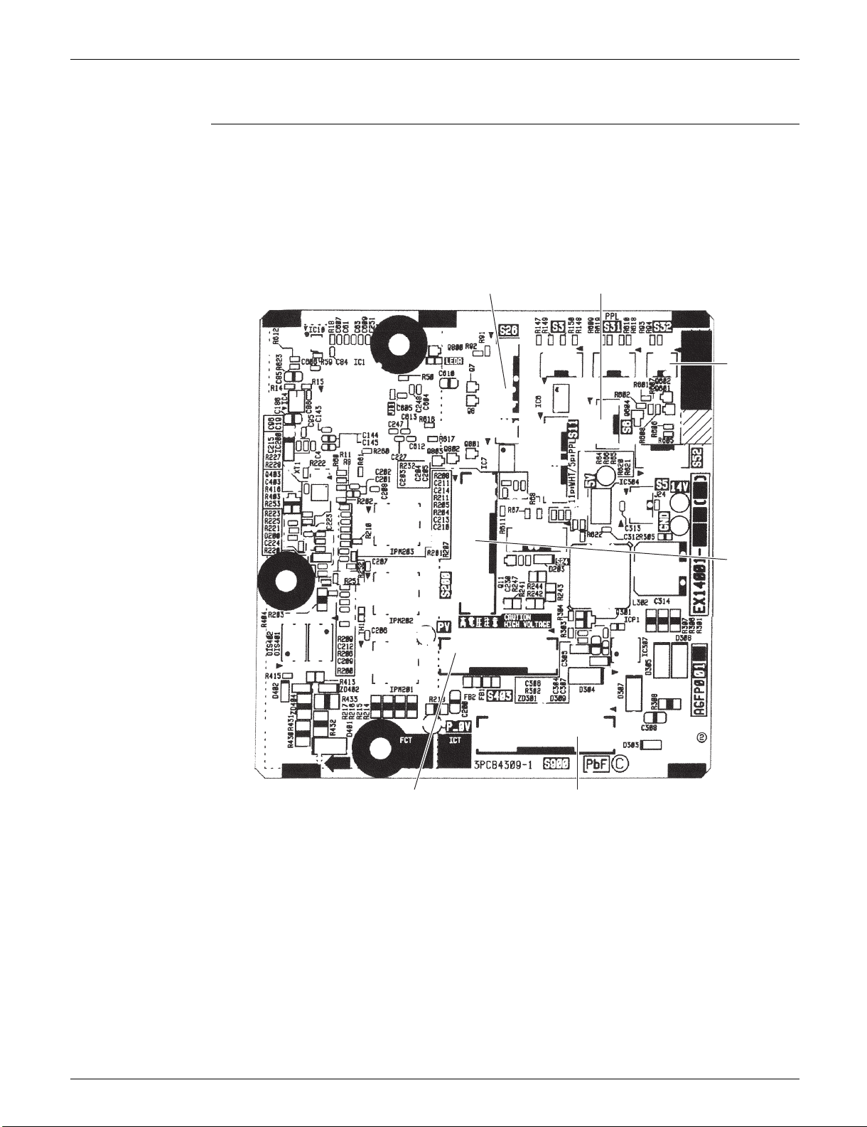
21 Part 3 Printed Circuit Board Connector Wiring Diagram
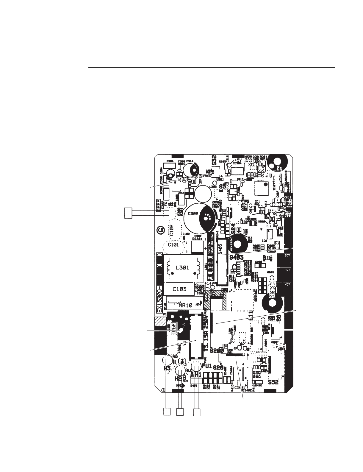
SiUS091601EA Indoor Unit
FG
S32
S26
H3 H2 H1
S6
S200
2P399175-9
FU1
V2
S403
1. Indoor Unit
1.1 FTX09/12NMVJU
Control PCB
(PCB1)
1) S6 Connector for swing motor (horizontal blade)
2) S26 Connector for display/signal receiver PCB (PCB2)
3) S32 Connector for indoor heat exchanger thermistor (R2T)
4) S200 Connector for DC fan motor
5) S403 Connector for adaptor PCB (option)
6) H1, H2, H3, FG Connector for terminal strip
7) FU1 Fuse (3.15 A, 250 V)
8) V2 Varistor
Part 3 Printed Circuit Board Connector Wiring Diagram 22
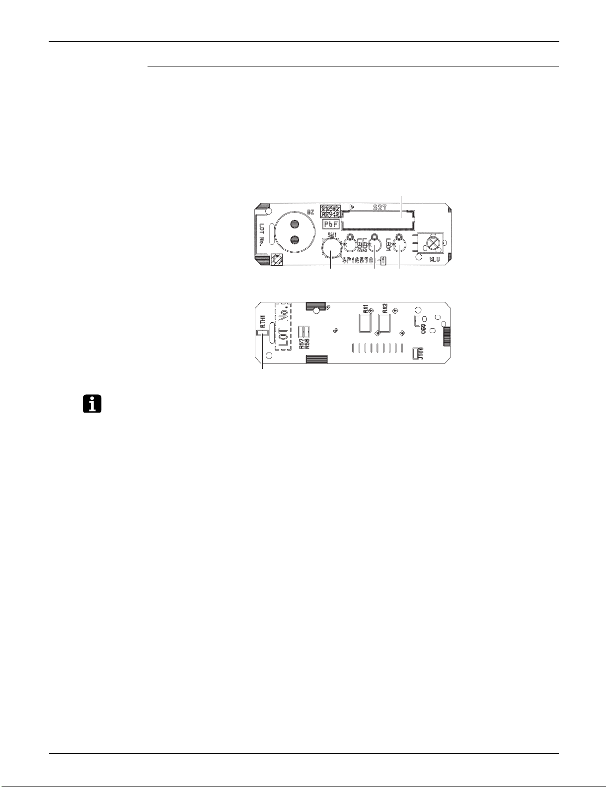
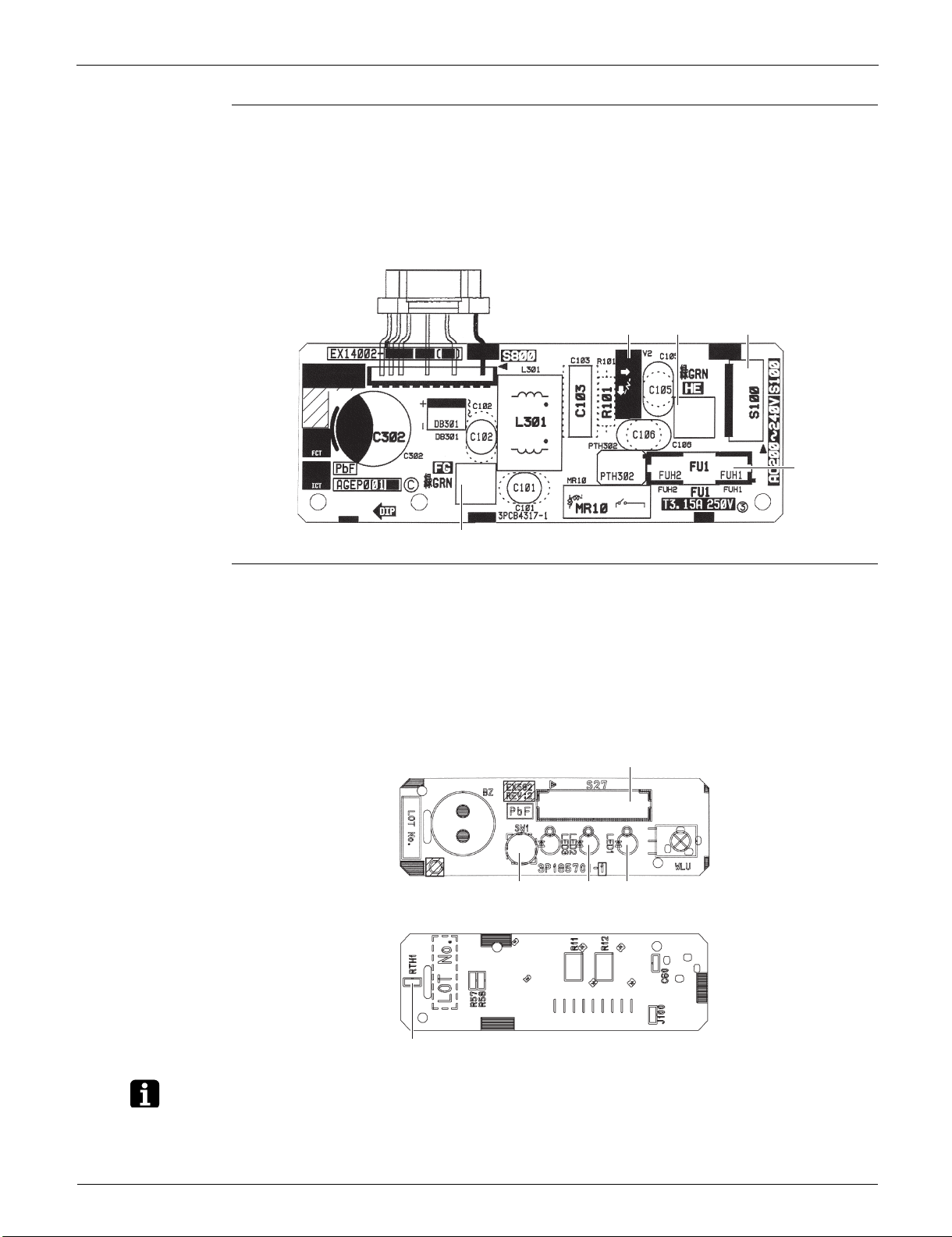
Indoor Unit SiUS091601EA
Note
Display/Signal
Receiver PCB
(PCB2)
1) S27 Connector for control PCB (PCB1)
2) SW1 (S1W) Indoor unit ON/OFF switch
(Forced cooling operation ON/OFF switch)
Refer to page 199 for details of forced cooling operation.
3) LED1 (H1P) LED for operation (green)
4) LED2 (H2P) LED for timer (yellow)
5) RTH1 (R1T) Room temperature thermistor
S27
SW1 LED2 LED1
(Solder side)
# LED3 is not mounted.
RTH1
3P185701-4
The symbols in the parenthesis are the names on the appropriate wiring diagram.
23 Part 3 Printed Circuit Board Connector Wiring Diagram
SiUS091601EA Indoor Unit
S26
S900
3P380931-1
S6
S32
S200
S403
1.2 FTX15NMVJU
Control PCB
(PCB2)
1) S6 Connector for swing motor (horizontal blade)
2) S26 Connector for display/signal receiver PCB (PCB3)
3) S32 Connector for indoor heat exchanger thermistor (R2T)
4) S200 Connector for DC fan motor
5) S403 Connector for adaptor PCB (option)
6) S900 Connector for filter PCB (PCB1)
Part 3 Printed Circuit Board Connector Wiring Diagram 24
Indoor Unit SiUS091601EA
Note
Filter PCB (PCB1)
1) S100 Connector for terminal strip
2) S800 Connector for control PCB (PCB2)
3) FG, HE Connector for ground
4) FU1 Fuse (3.15 A, 250 V)
5) V2 Varistor
S800
V2 HE S100
FU1
Display/Signal
Receiver PCB
(PCB3)
FG
1) S27 Connector for control PCB (PCB2)
2) SW1 (S1W) Indoor unit ON/OFF switch
(Forced cooling operation ON/OFF switch)
Refer to page 199 for details of forced cooling operation.
3) LED1 (H1P) LED for operation (green)
4) LED2 (H2P) LED for timer (yellow)
5) RTH1 (R1T) Room temperature thermistor
SW1 LED2 LED1
# LED3 is not mounted.
(Solder side)
3P380932-1
S27
RTH1
3P185701-4
The symbols in the parenthesis are the names on the appropriate wiring diagram.
25 Part 3 Printed Circuit Board Connector Wiring Diagram
 Loading...