

Daikin RWEYQ72PTJU, RWEYQ84PTJU, RWEYQ144PTJU, RWEYQ168PTJU, RWEYQ216PTJU Engineeiring Data
...
EDUS 30 - 900 - N
AMERICASAMERICAS
Installation

EDUS30-900-N
Installation of Outdoor Units 1
Installation of
Outdoor Units
1. Center of Gravity .........................................................................................2
2. Installation and Repair Space Drawing .......................................................3
3. REFNET Pipe System.................................................................................4
3.1 Layout Example............................................................................................ 4
3.2 Max. Refrigerant Piping Length.................................................................... 5
3.3 Field Refrigerant Piping................................................................................ 6
3.4 REFNET Joints and Headers ....................................................................... 7
4. REFNET Pipe System.................................................................................9
4.1 REFNET Joint (Branch Kit) .......................................................................... 9
4.2 REFNET Header (Branch Kit) .................................................................... 17
4.3 Outdoor Unit Multi Connection Piping Kit ................................................... 25
5. Installation .................................................................................................27
5.1 RWEYQ72, 84, 144, 168, 216, 252PTJU................................................... 27
Center of Gravity EDUS30-900-N
2 Installation of Outdoor Units
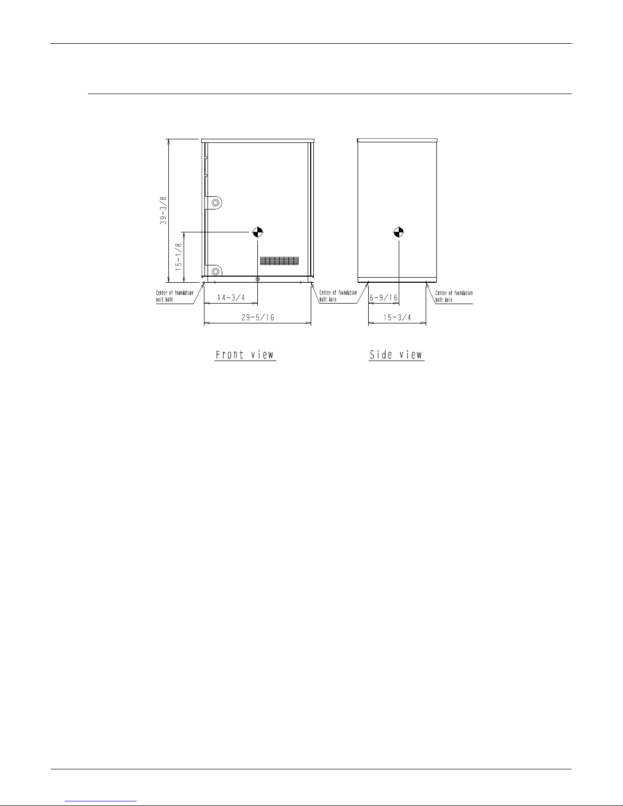
1. Center of Gravity
RWEYQ72, 80PTJU
4D055409
4D066040
EDUS30-900-N Installation and Repair Space Drawing
Installation of Outdoor Units 3
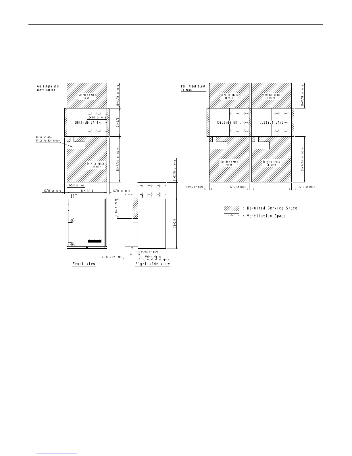
2. Installation and Repair Space Drawing
RWEYQ72, 84PTJU
3D066039
REFNET Pipe System EDUS30-900-N
4 Installation of Outdoor Units
3. REFNET Pipe System
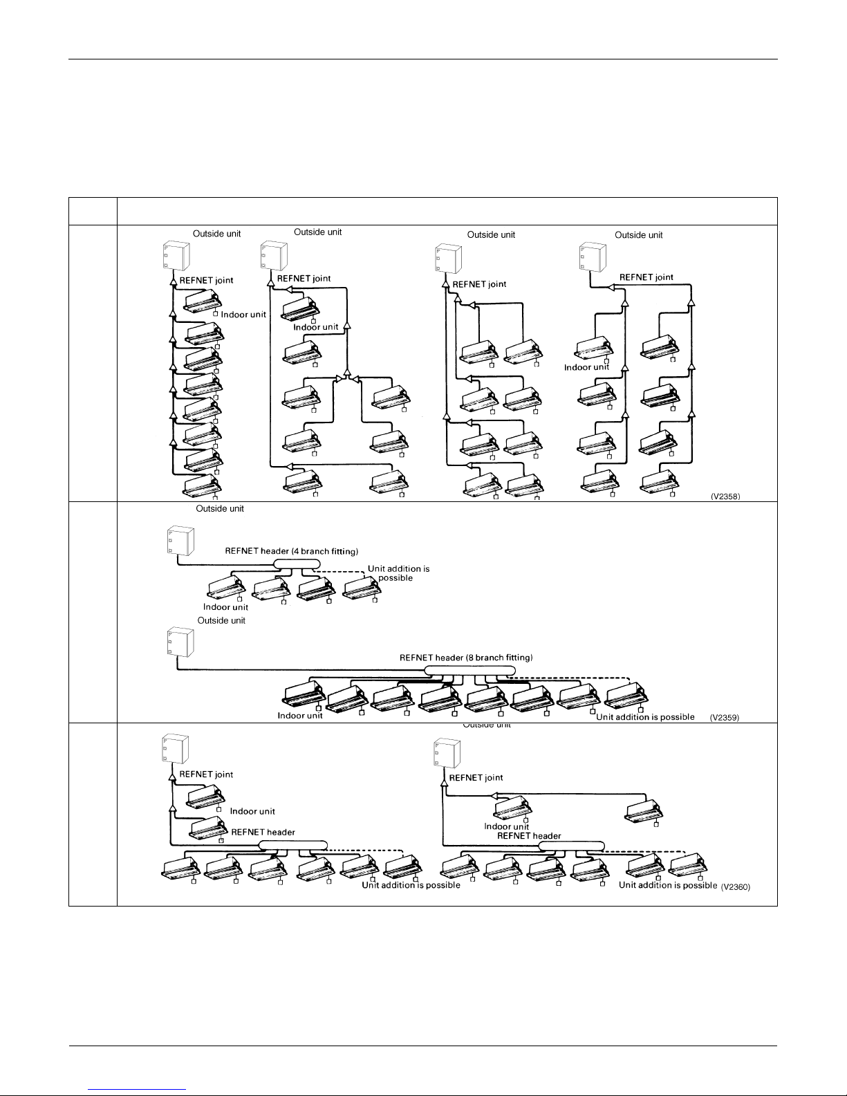
3.1 Layout Example
3.1.1 Heat Pump System
Use of the particular branch fitting appropriate to each individual unit type not only permits the pipes to be laid
with ease but also increases the reliability of the system as a whole.
Units can be added by connecting them directly to the REFNET header or REFNET joint. Further branches cannot be included in the system
below the REFNET header branch. NOTES:
1.When the capacity ratio of the indoor system to the outside unit is more than 100% and when all the indoor units are in operation at the same
time then the rated capacity of each unit will be somewhat reduced.
2.Special purpose REFNET pipe components must be used for all the pipe work. For further details concerning choosing components, see
REFNET and Piping Selection Rules.
3.The Daikin REFNET kits are supplied with insulation intended to fit over the main body of the REFNET joint after installation of the REFNET kit is
complete.
4.IMPORTANT:In applications where the REFNET kits are installed in an environment requiring fire-rated materials to be used, it is necessary for
the installer to obtain from a thired party supplier and to utilize, for insulation, fire-rated materials that meet all applicable building codes and
other requirements.The factory-provided insulation that is supplied with the REFNET kit should be discarded in a manner meeting all applicable laws.
Type of
fitting
Sample systems
Line branch fitting
(Pipes containing REFNET joints only)
Header branch fitting
(Piping consists of REFNET headers only)
Mixed branch fittings
(Piping including both headers and joints)
EDUS30-900-N REFNET Pipe System
Installation of Outdoor Units 5
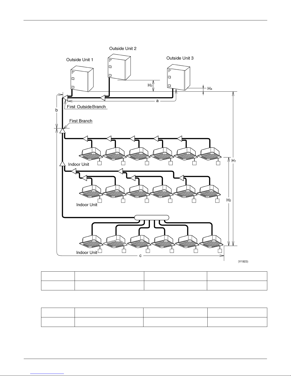
3.2 Max. Refrigerant Piping Length
3.2.1 Heat Pump System
Max. Refrigerant Piping Length (Actual Piping Length)
Total Extension length
Total Piping length from outside unit to all indoor units 300m
Max. Level Difference
Notes:
1. Be sure to use a REFNET Piping Kit for the branch of piping.
2. A Branch Part can not be installed to the down flow of the REFNET Header.
3. If the outside unit is located under the indoor unit, the level difference is a maximum of 131.2ft.
4. For geothermal applications, if the condenser is lower than the indoor units, the maximum vertical separation is 65 ft.
First outside Branch ~ Outside units
[a]
First Branch ~ Indoor Units
[c]
Outside Units ~ Indoor Units
[b+c]
Max. Refrigerant
Piping Length (ft)
33 ft or less 131ft or less 394 ft or less
Outside Units ~ Indoor Units
[H
1
]
Between the Indoor Units
[H2]
Between the Outside Units
[H3 , H4]
Max. Level
Difference (ft)
164 ft or less
Note 3
49 ft or less 6.6 ft or less
REFNET Pipe System EDUS30-900-N
6 Installation of Outdoor Units
3.3 Field Refrigerant Piping
3.3.1 Heat Pump Series
1. The following materials should be used for all refrigerant piping.
Materials: Deoxidized phosphorous seamless copper pipe or equivalent
2. The tips for insulation
Both Gas, Liquid piping must be insulated.
Materials: Glass fiber or heat resistant polyethylene foam.
Thickness: 1/2 inch or more (depending on National or Local Code)
Heat resistance: Be sure to use insulation that is designed for use with HVAC Systems.
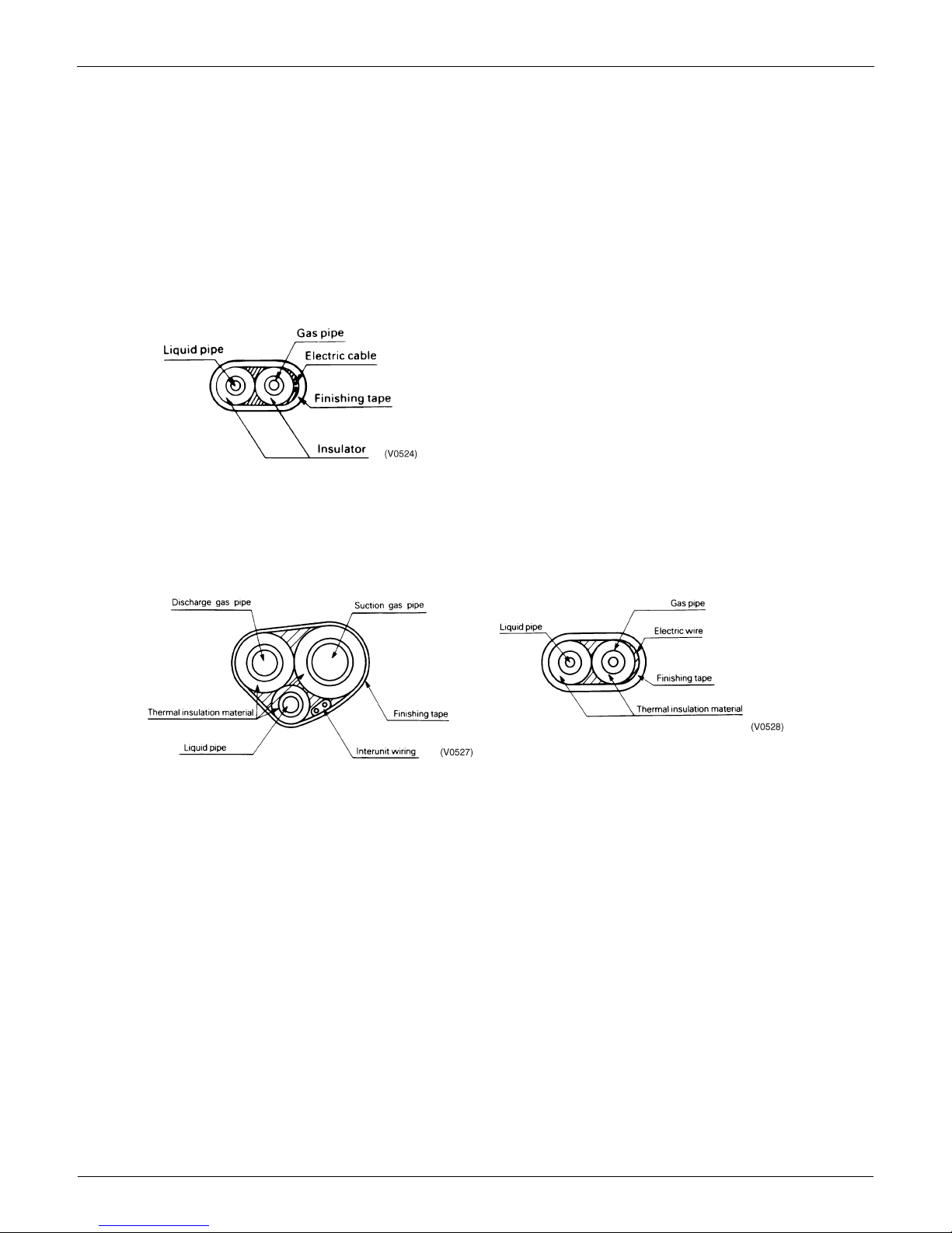
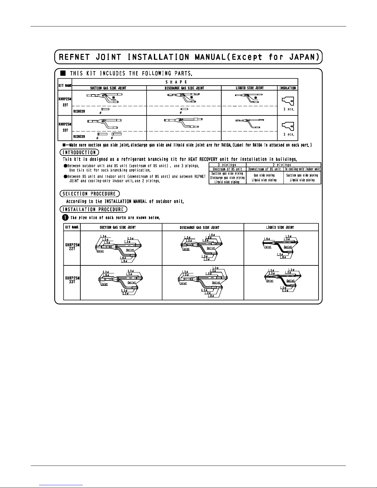
3.3.2 Heat Recovery Series
Suction, Discharge Gas piping, liquid piping must be insulated.
Example of thermal insulation work.
Insulation of both liquid and gas pipe
3 piping section (between outdoor unit and BS unit) 2 piping section (between BS unit and indoor unit)
EDUS30-900-N REFNET Pipe System
Installation of Outdoor Units 7
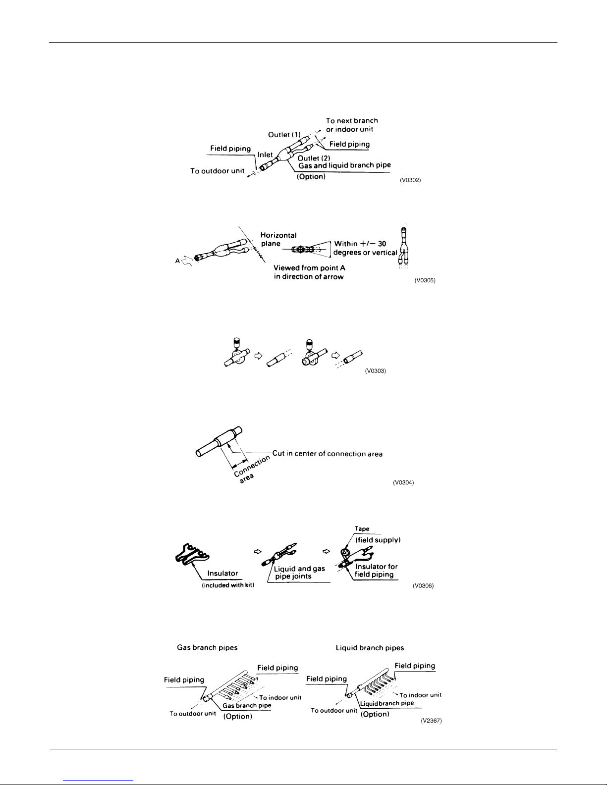
3.4 REFNET Joints and Headers
3.4.1 REFNET Joints
For gas and liquid branch pipes
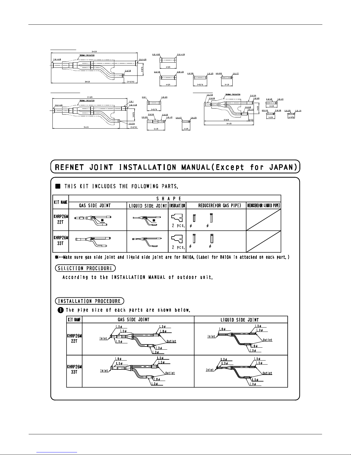
Make sure that all branch pipes are fitted such that they branch either horizontally or vertically.
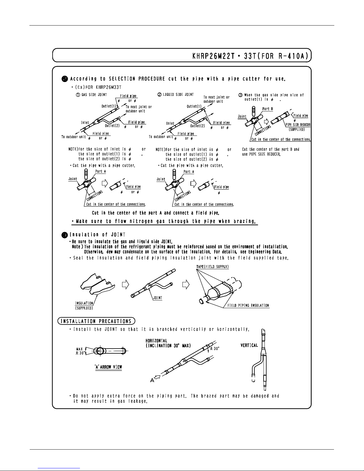
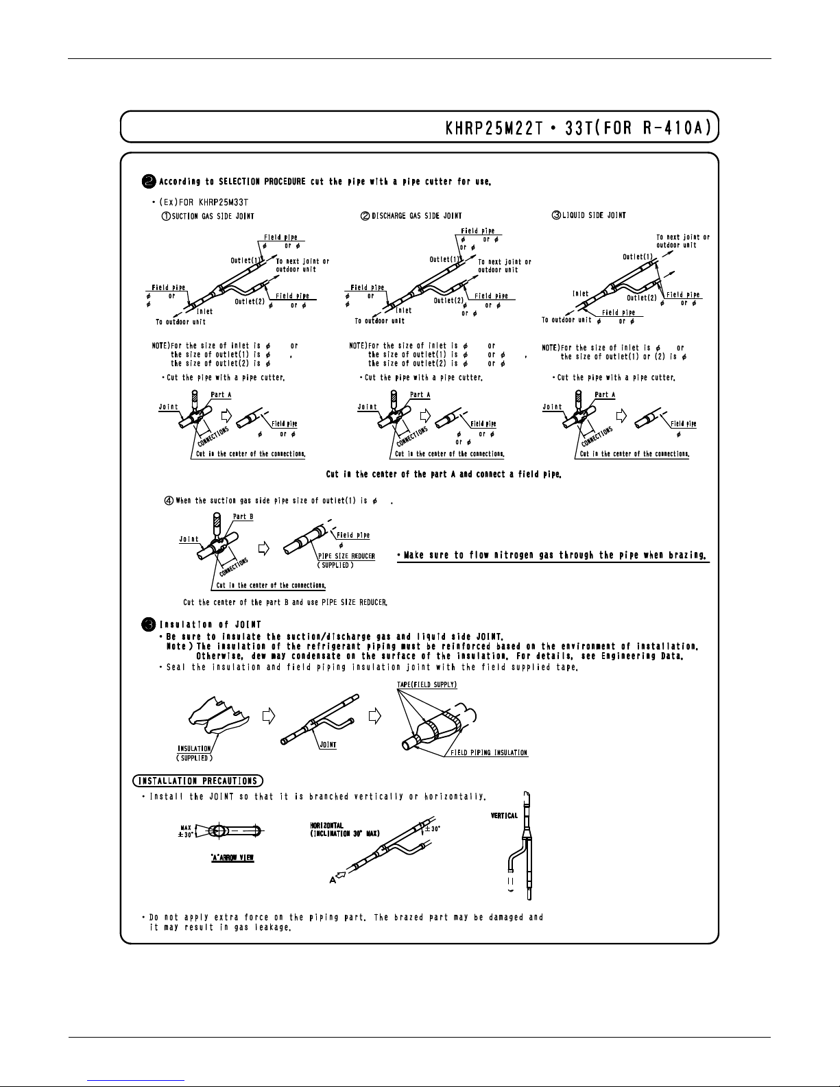
When the size of the selected field piping is different from that of branch pipe then the connecting section should be
cut with a pipe cutter as shown in the figure below.
When you are cutting an inlet or outlet pipe with a pipe cutter make sure that you make the cut in the center of the
connection area.
Branch pipes must be insulated in accordance with the handbook which comes with each kit.
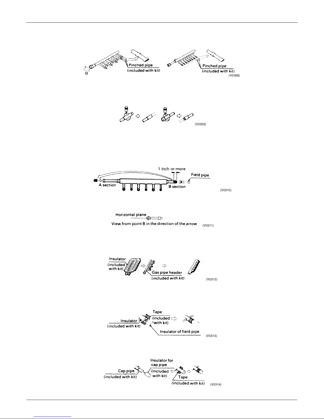
3.4.2 REFNET Header
REFNET Pipe System EDUS30-900-N
8 Installation of Outdoor Units
When the number of indoor units to be connected to the branch pipes is less than the number of branch pipes
available for connection then cap pipes should be fitted to the surplus branches.
When the size of the selected field piping is different from that of branch pipe then the connecting section should be
cut with a pipe cutter as shown in the figure below.
When field piping is connected to the B section of the inlet/outlet pipe on the outdoor unit side of the liquid pipe
header.
Cut the B section with a pipe cutter as shown below and connect it to the A section.
Connect the flared section of the field pipe to the B section.
Fit the branch pipe so that the branch lies in a horizontal plane.
The branch pipe must be insulated in accordance with the instruction manual which comes with each kit.
1. Use the insulator included in the kit to insulate the header.
2. Joints between insulators included in the kit and those already applied to the field piping should be sealed with the
tape which is also included in each kit.
3. Any cap pipes should also be insulated using the insulator provided with each kit and then taped as described above.

EDUS30-900-N REFNET Pipe System
Installation of Outdoor Units 9
4. REFNET Pipe System
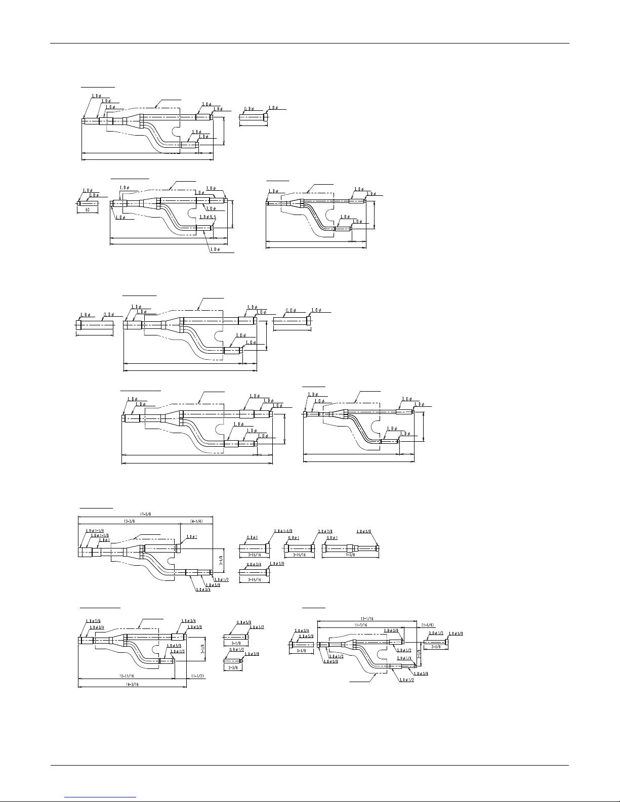
4.1 REFNET Joint (Branch Kit)
KHRP26M22T
KHRP26M33T
KHRP26M72TU
KHRP26M73TU
Gas Side
Insulation
Insulation
(unit:in.)
Liquid Side
D3K03622C
1/2
5/8
3/4
5/8
1/2
5/8
1/2
3-1/8
1-5/8
13-5/16
14-15/16
7/8
5/8
3/4
3-15/16
3/4
3-1/8
3/8
3/8
1/4
3-1/8
1/4
3/8
1-9/16
9-13/16
11-7/16
Gas Side
Insulation
Insulation
Liquid Side
D3K03623A
7/8
3/4
3/4
5/8
5/8
1/2
3-1/8
1-1/2
12-11/16
14-3/16
1
7/8
3-15/16
3/4
7/8
3-15/16
1/2
3/8
3/8
1/4
3-1/8
3/8
1/4
1-9/16
10-1/4
11-13/16
Liquid Side
Gas Side
Insulation
Insulation
D3K04887A
Liquid Side Joint
Gas Side Joint
D3K05572
REFNET Pipe System EDUS30-900-N
10 Installation of Outdoor Units
KHRP25M22T
KHRP25M33T
KHRP25M72TU
D3K03626B
Suction gas side
Discharge gas side
Liquid side
Insulation
Insulation
Insulation
1/2
5/8
3/4
5/8
1/2
5/8
3/4
3-1/8
3-1/8
5/8
1/2
1-5/8
13-5/16
14-15/16
3/8
1/2
5/8
1/2
1/2
3/8
5/8
3-1/8
1-5/8
1-9/16
11-13/16
13-3/8
3/8
3/8
1/4
3/8
1/4
3-1/8
1-9/16
9-13/16
11-7/16
D3K03627B
Suction gas side
Discharge gas side
Liquid side
Insulation
Insulation
Insulation
1
7/8
3-15/16
7/8
3/4
3/4
5/8
3/4
7/8
3-15/16
5/8
1/2
1-1/2
12-11/16
14-3/16
5/8
3/4
3/4
5/8
1/2
3-1/8
3-1/8
5/8
1/2
3/8
1-5/8
14-1/2
16-1/16
1/2
3/8
3/8
1/4
3/8
1/4
3-1/8
1-9/16
10-1/4
11-13/16
D3K04888A
Liquid sideDischarge gas side
Insulation
Insulation
Insulation
Suction gas side
EDUS30-900-N REFNET Pipe System
Installation of Outdoor Units 11
KHRP25M73TU
KHRP26M22T, KHRP26M33T
C : 3P113149B
D3K05573
Liquid side JointDischarge gas side Joint
Suction gas side Joint
3/4
7/8
7/8
1
1/2
3/4
5/8
5/8
3/8
1/2
3/8
3/8
1/4
1/4
3/8
3/8
1/4
1/4
3/8
5/8
1/2
1/2
7/8
3/4
3/4
5/8
5/8
1/2
REFNET Pipe System EDUS30-900-N
12 Installation of Outdoor Units
C : 3P113149B
3/4 5/8
3/4 5/8
5/8 1/2
3/8 1/4
7/8
7/8
1/2
3/8
3/8
3/8
3/8
3/8
3/4
3/4
5/8
7/8 3/4
EDUS30-900-N REFNET Pipe System
Installation of Outdoor Units 13
KHRP25M22T, KHRP25M33T
C : 3P113621B
3/4
3/8
7/8 1
1/2
7/8
3/4
5/8
1/2
1/2
3/8
1/4
3/8
3/8
1/4
5/8
5/8
1/2
3/8
3/4
3/4
5/8
3/4
5/8
1/2
1/2
1/2
5/8
5/8
1/2
1/2
5/8
1/2
3/8
3/8
3/8
3/8
1/4
1/4
3/8
5/8
5/8
3/4
REFNET Pipe System EDUS30-900-N
14 Installation of Outdoor Units
C : 3P113621B
3/4 5/8
5/8
3/4
3/4
5/8
7/8
7/8
3/4
3/4
5/8
3/8
3/8
3/4 5/8
5/8
1/2
1/2
7/8
3/4
3/4
5/8
3/4 5/8
1/2 3/8
3/8 1/4
1/2
5/8 1/2
3/8
3/4 5/8
3/8
1/2
EDUS30-900-N REFNET Pipe System
Installation of Outdoor Units 15
KHRP25M72TU, KHRP26M72TU, KHRP25M73TU, KHRP26M73TU
3P161697D
 Loading...