

Page 1
English
Deutsch
Français
Nederlands
156077 PGDK
156075 PGMK
06/2019
Italiano
Español
Português
Ελληνικά
j zyk polskię
Page 2

Page 3
156077 PGDK
156075 PGMK
Read manual before use!
English
Observe all safety information!
Keep manual for future use!
Page 4

About these operating instructions
1 About these operating instructions
These operating instructions describe the pump assembly with and without
mixer (also referred to as "product" in these operating instructions).
These operating instructions are part of the product.
• You may only use the product if you have fully read and understood these
operating instructions.
• Verify that these operating instructions are always accessible for any type
of work performed on or with the product.
• Pass these operating instructions as well as all other product-related documents on to all owners of the product.
• If you feel that these operating instructions contain errors, inconsistencies, ambiguities or other issues, contact the manufacturer prior to using
the product.
There operating instructions are protected by copyright and may only be
used as provided for by the corresponding copyright legislation. We reserve
the right to modifications.
The manufacturer shall not be liable in any form whatsoever for direct or consequential damage resulting from failure to observe these operating instructions or from failure to comply with directives, regulations and standards and
any other statutory requirements applicable at the installation site of the product.
EN
FA PG - 06/2019 - 008.15 442 99_02 - EN
2
Page 5
Information on safety
2 Information on safety
2.1 Safety messages and hazard categories
These operating instructions contain safety messages to alert you to potential hazards and risks. In addition to the instructions provided in these operating instructions, you must comply with all directives, standards and safety
regulations applicable at the installation site of the product. Verify that you are
familiar with all directives, standards and safety regulations and ensure compliance with them prior to using the product.
Safety messages in these operating instructions are highlighted with warning
symbols and warning words. Depending on the severity of a hazard, the
safety messages are classified according to different hazard categories.
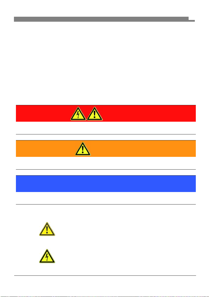
DANGER
DANGER indicates a hazardous situation, which, if not avoided, will
result in death or serious injury.
WARNING
WARNING indicates a potentially hazardous situation, which, if not avoided,
can result in serious injury or equipment damage.
EN
NOTICE
NOTICE indicates a hazardous situation, which, if not avoided, can
result in equipment damage.
In addition, the following symbols are used in these operating instructions:
This is the general safety alert symbol. It alerts to injury hazards or equipment da
tions in conjunction with this symbol to help avoid possible
death, injury or equipment damage.
This symbol alerts to hazardous electrical voltage. If this
symbol is used in a safety message, there is a hazard of
electric shock.
mage. Comply with all safety instruc-
FA PG - 06/2019 - 008.15 442 99_02 - EN
3
Page 6

Information on safety
2.2 Intended use
This product may only be used to circulate the following liquids in intrinsically
safe, sealed, thermal heating systems:
• Heating circuit water as per VDI 2035
• Water/glycol mixtures with a maximum admixture of 20 %
Any use other than the application explicitly permitted in these operating
instructions is not permitted and causes hazards.
Verify that the product is suitable for the application planned by you prior to
using the product. In doing so, take into account at least the following:
• All directives, standards and safety regulations applicable at the installation site of the product
• All conditions and data specified for the product
• The conditions of the planned application
In addition, perform a risk assessment in view of the planned application,
according to an approved risk assessment method, and implement the
appropriate safety measures, based on the results of the risk assessment.
Take into account the consequences of installing or integrating the product
into a system or a plant.
When using the product, perform all work and all other activities in conjunction with the product in compliance with the conditions specified in the operating instructions and on the nameplate, as well as with all directives, standards and safety regulations applicable at the installation site of the product
EN
FA PG - 06/2019 - 008.15 442 99_02 - EN
4
Page 7

Information on safety
2.3 Predictable incorrect application
The product must never be used in the following cases and for the following
purposes:
• Use with drinking water
• Use with adherent, corrosive or flammable fluids
• Operation in systems with temperatures exceeding 110 °C
(for example, solar systems)
2.4 Qualification of personnel
Only appropriately trained persons who are familiar with and understand the
contents of these operating instructions and all other pertinent product documentation are authorized to work on and with this product.
These persons must have sufficient technical training, knowledge and experience and be able to foresee and detect potential hazards that may be
caused by using the product
All persons working on and with the product must be fully familiar with all
directives, standards and safety regulations that must be observed for performing such work.
2.5 Personal protective equipment.
Always wear the required personal protective equipment. When performing
work on and with the product, take into account that hazards may be present
at the installation site which do not directly result from the product itself.
EN
2.6 Modifications to the product
Only perform work on and with the product which is explicitly described in
these operating instructions. Do not make any modifications to the product
which are not described in these operating instructions.
FA PG - 06/2019 - 008.15 442 99_02 - EN
5
Page 8

Transport and storage
3 Transport and storage
The product may be damaged as a result of improper transport or storage.
NOTICE
DAMAGE TO THE PRODUCT
• Verify compliance with the specified ambient conditions during transport or
storage of the product.
• Use the original packaging when transporting the product.
• Store the product in a clean and dry environment.
• Verify that the product is protected against shocks and impact during transport and storage.
Failure to follow these instructions can result in equipment damage.
EN
FA PG - 06/2019 - 008.15 442 99_02 - EN
6
Page 9

Product description
4 Product description
The product is a pre-assembled, tightness-tested and heat-insulated pump
assembly.
The universal insulation allows for the installation of virtually any standard circulation pump (with G1
reworking of the insulation.
The second ball valve in the return line lets you replace the pump without
draining the system.
In addition, the system is modular so that the flow line can be mounted at the
left or the right side. Optional temperature probes Ø 6 mm can be mounted
to all ball valves.
1
/
connection and a length of 180 mm) without major
2
EN
FA PG - 06/2019 - 008.15 442 99_02 - EN
7
Page 10
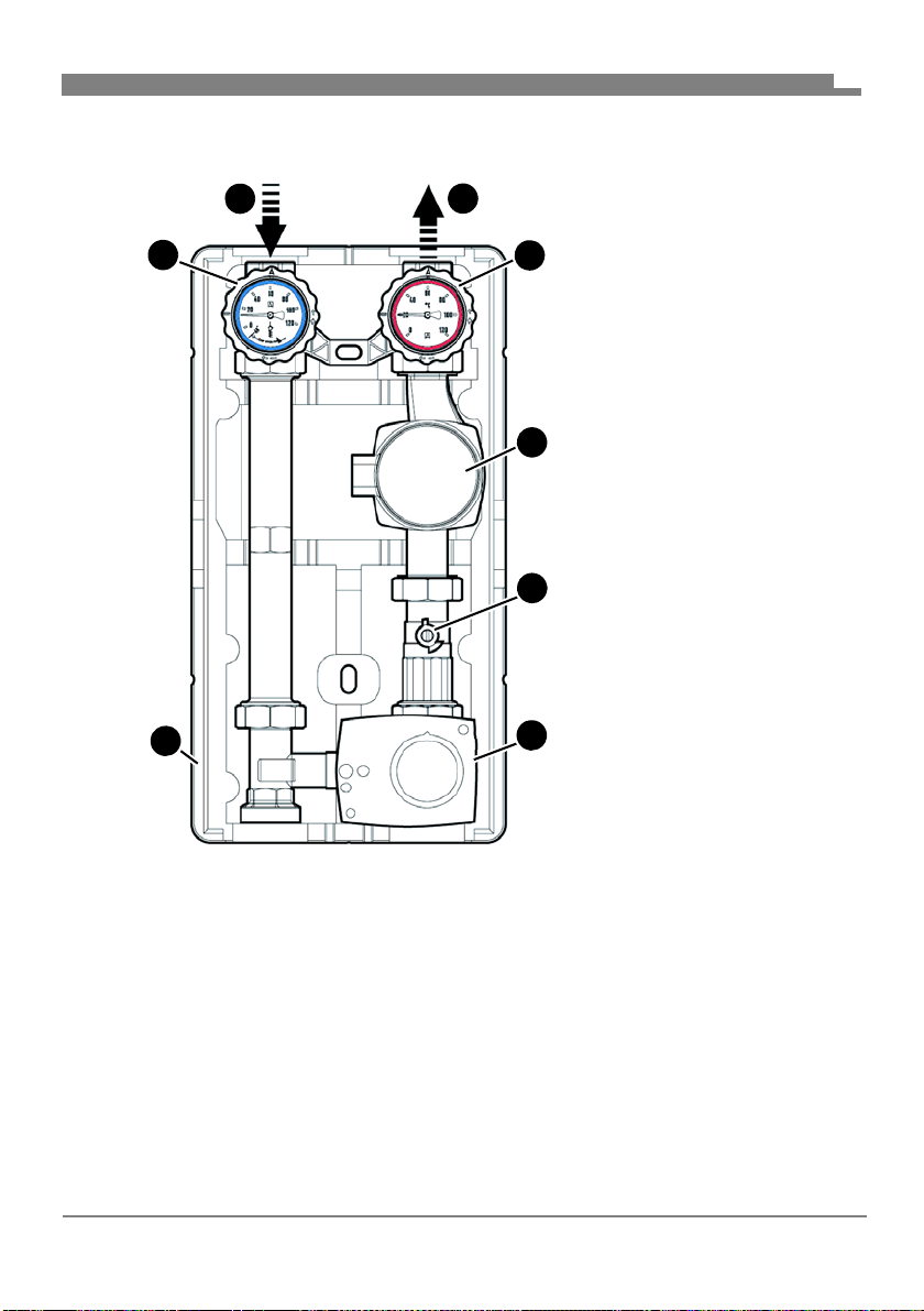
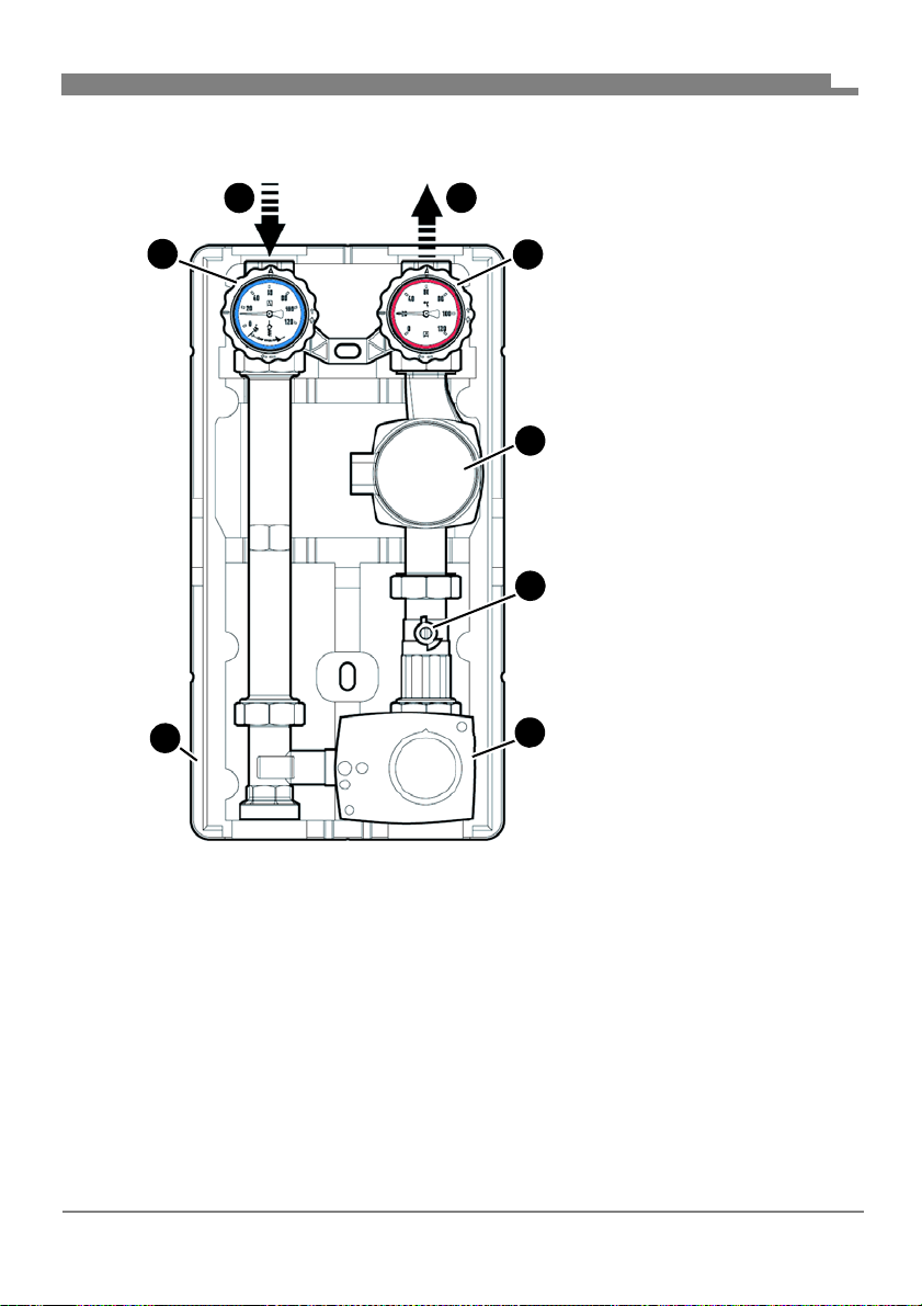
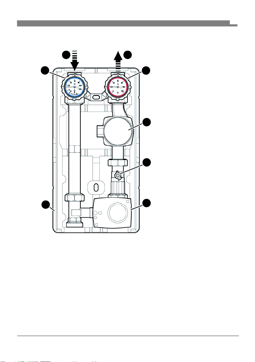
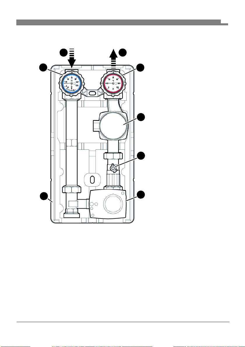
4.1 Overview
1
2
B
C
D
E
F
A
Product description
1. Return
2. Flow
A. Ball valve, can be shut off,
B. Ball valve, can be shut off,
C. Circulation pump (various
D. Ball valve
E. 3-way mixer with actuator
F. Insulation
EN
with thermometer blue
and gravity brake
with thermometer red
manufacturers)
Fig. 1: PrimoTherm® components
FA PG - 06/2019 - 008.15 442 99_02 - EN
8
Page 11
Product description
4.2 Versions
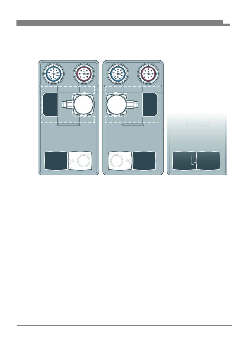
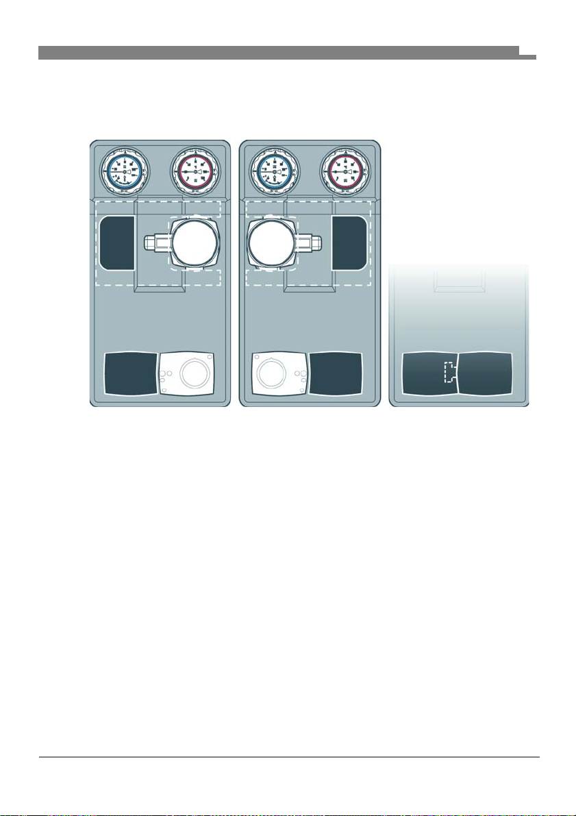
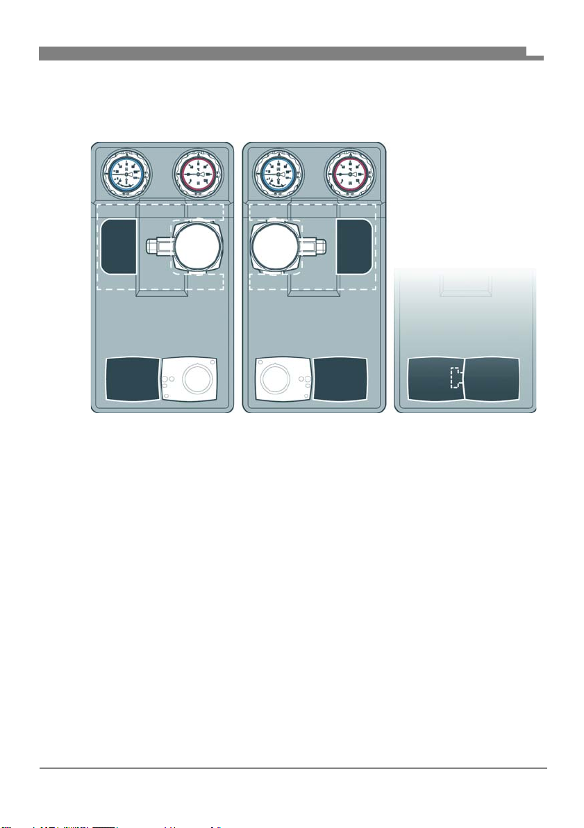
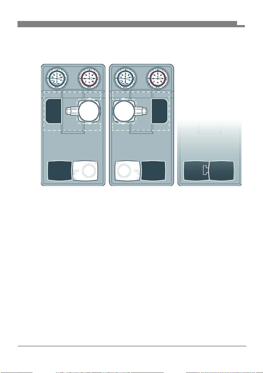
The variable insulation can be used for applications with flow at the left and
flow at the right.
Fig. 2: Flow right (left figure)
Fig. 3: Flow left (centre figure)
Fig. 4: Without actuator (right figure)
EN
FA PG - 06/2019 - 008.15 442 99_02 - EN
9
Page 12
Product description
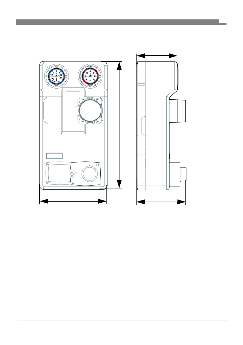
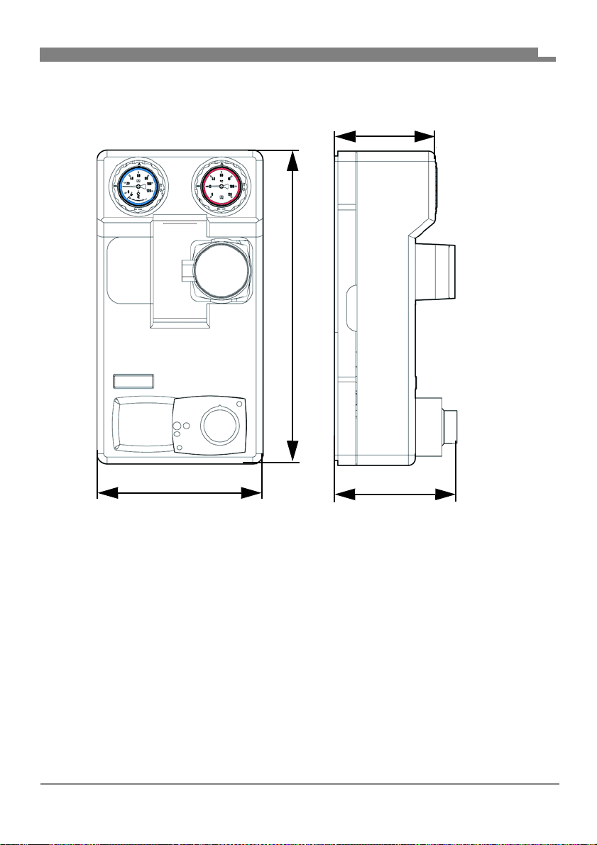
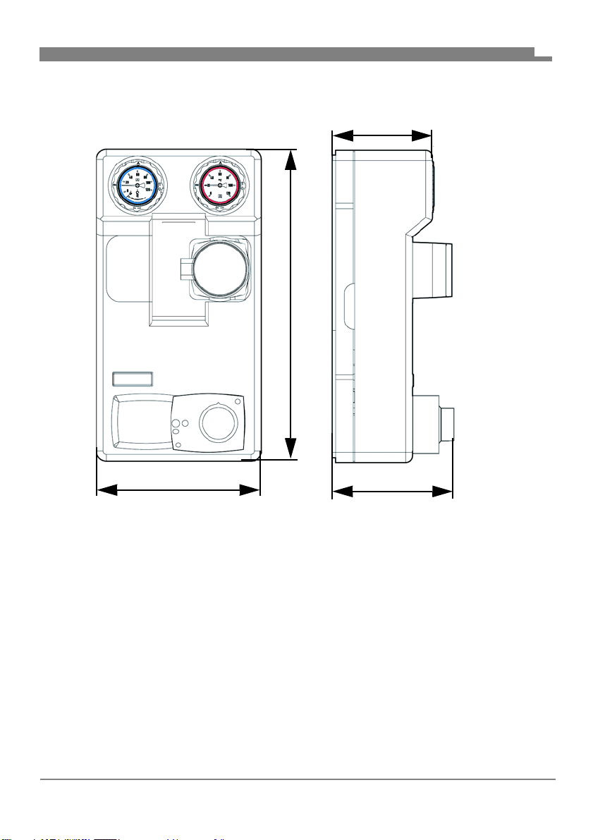
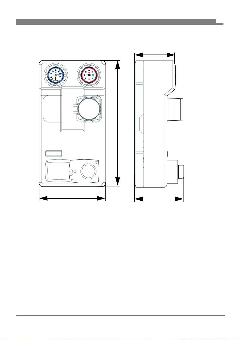
Approx. 250
Approx.
Approx. 475
Approx. 152
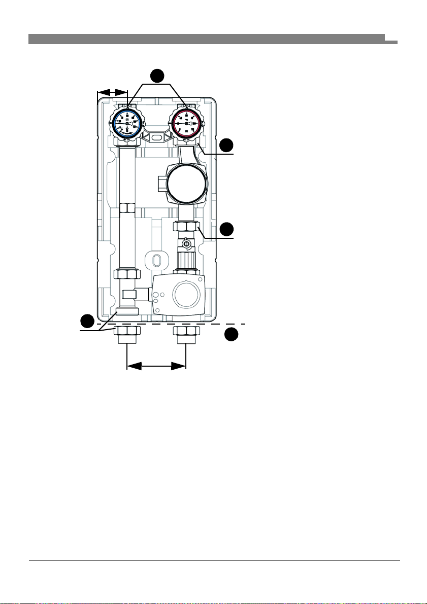
4.3 Dimensions and connections
EN
FA PG - 06/2019 - 008.15 442 99_02 - EN
10
Page 13
Product description
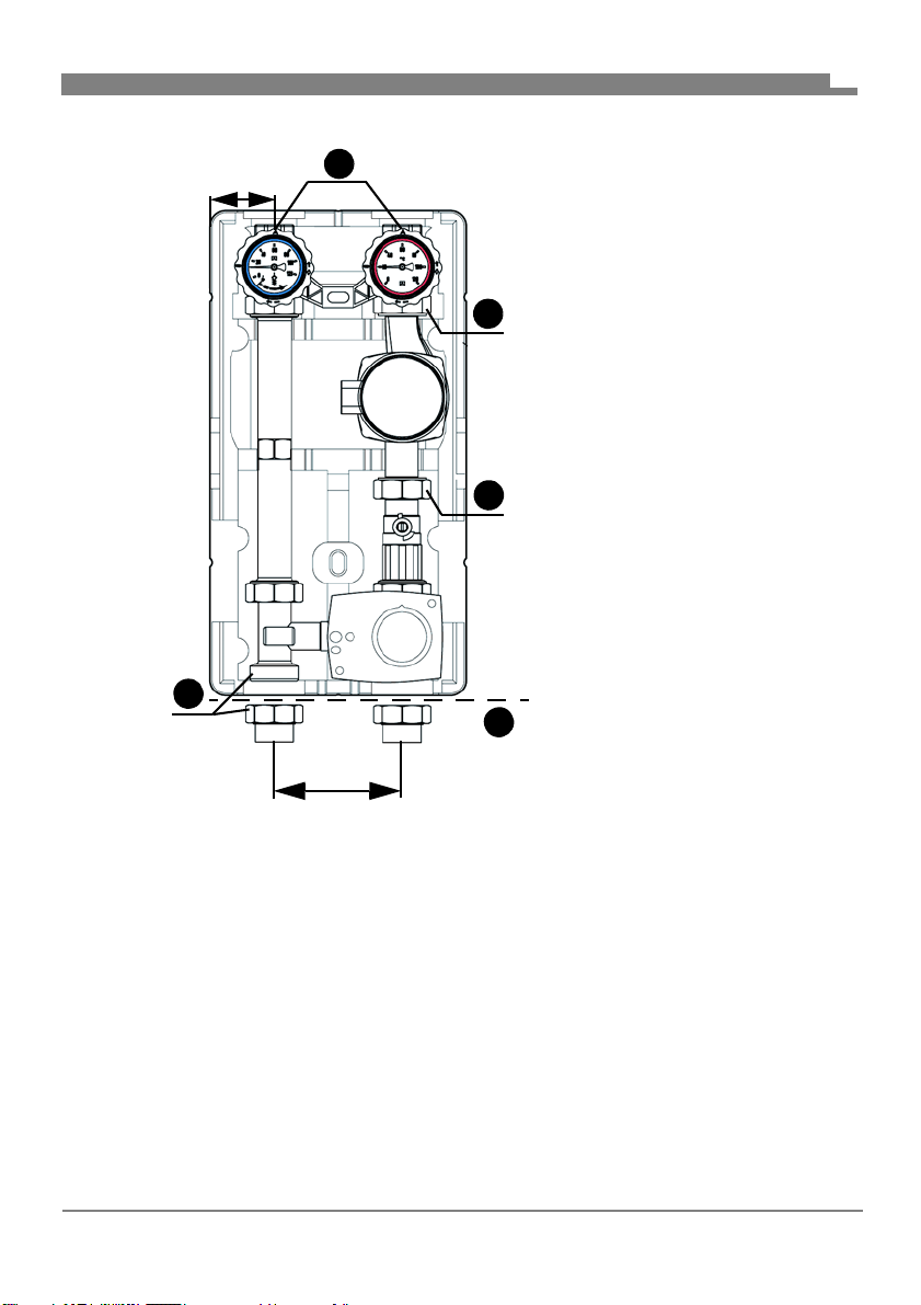
B
1
B
B
A
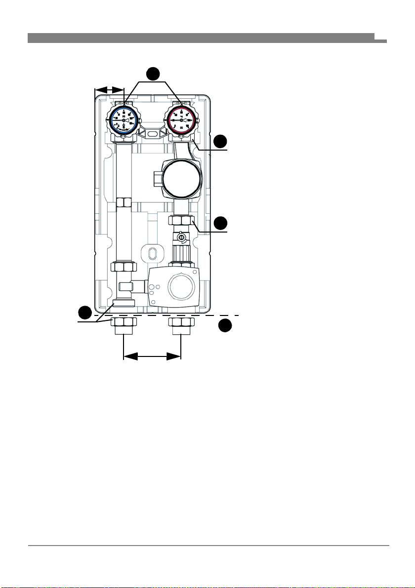
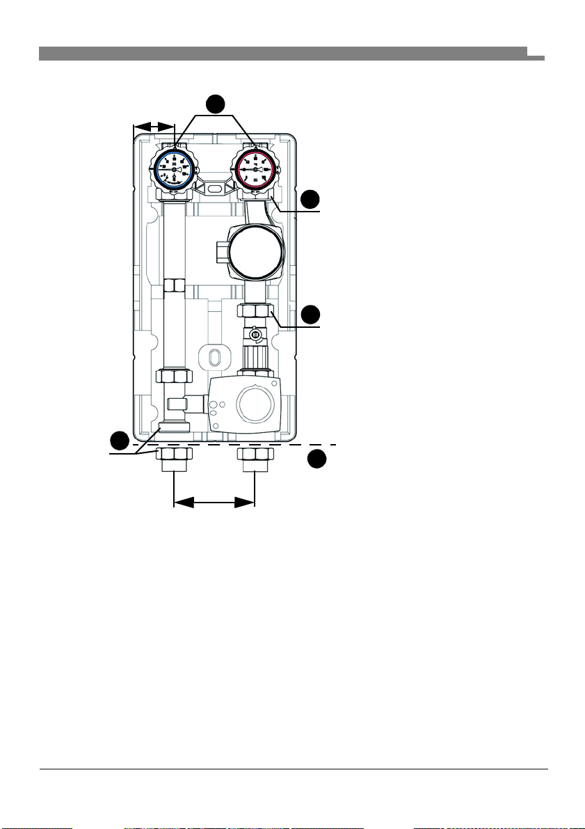
Approx. 125
Approx. 60
A. G1
B. G1½
EN
4.4 Approvals, conformities, certifications
See operating instructions of the manufacturer of the circulation pump for versions with circulation pump.
FA PG - 06/2019 - 008.15 442 99_02 - EN
11
Page 14
Product description
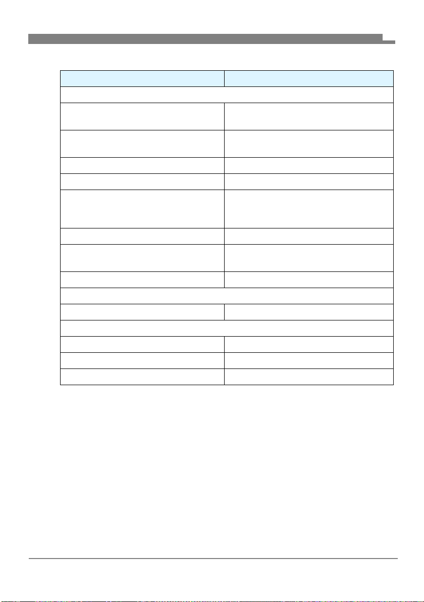
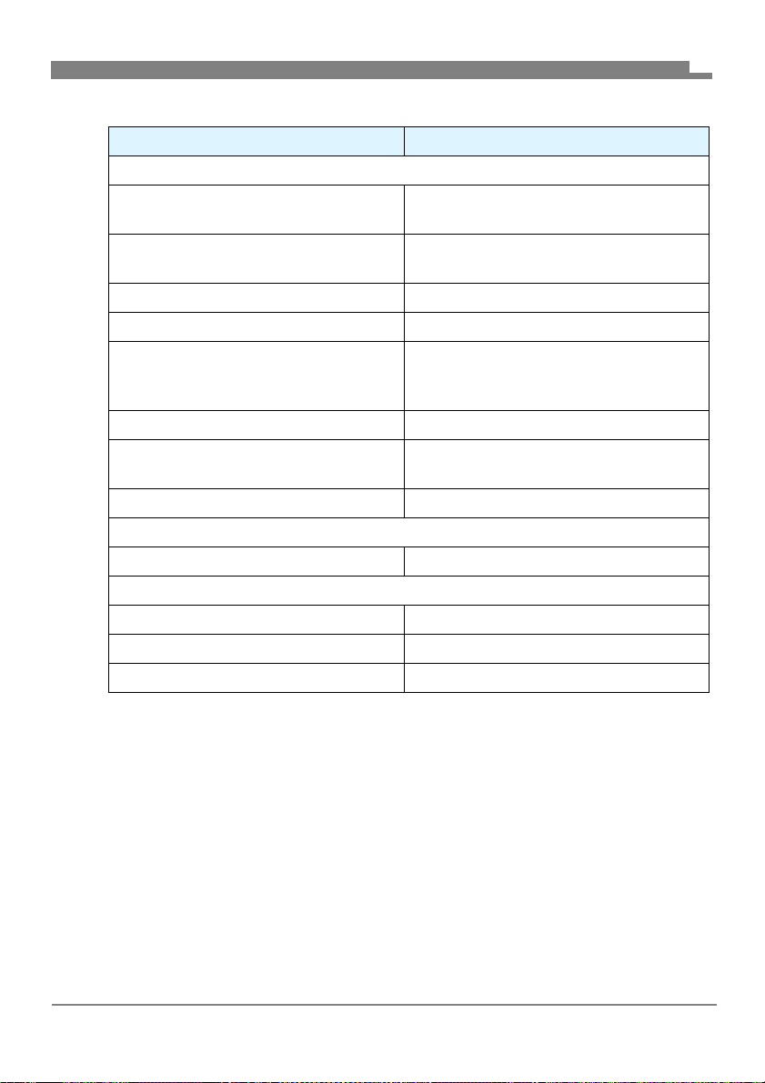
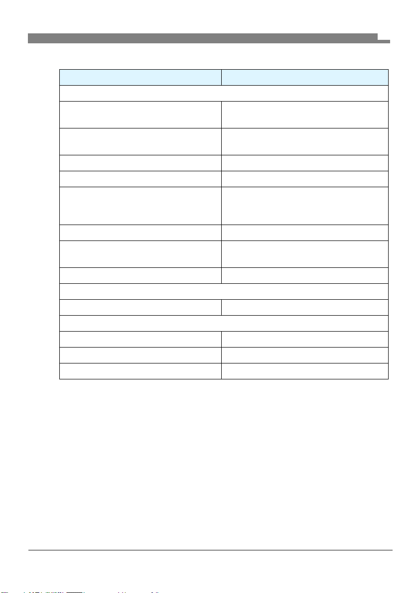
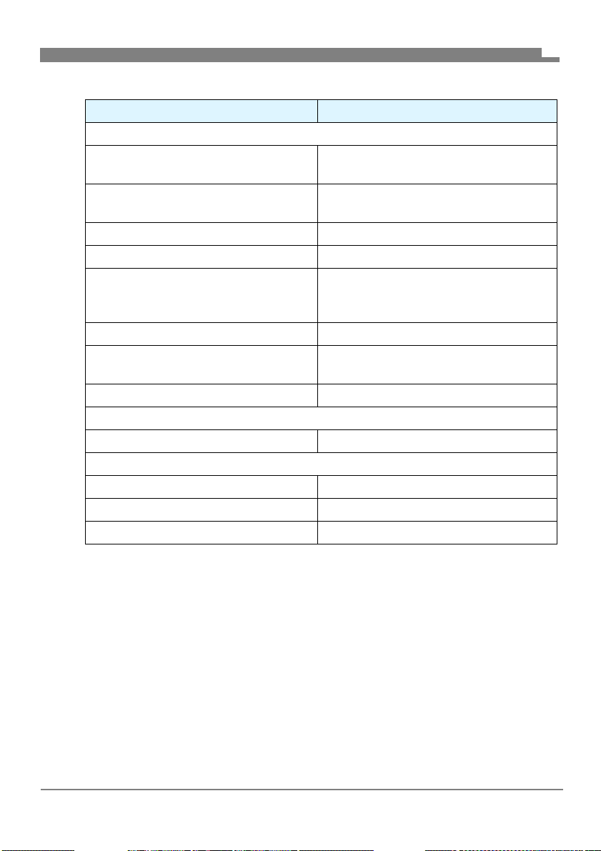
4.5 Technical specifications
Parameter Value
General specifications
Dimensions with insulation
(W x H x D)
Weight Approx. 5.5 kg with mixer
Material of fittings Brass
Insulation material Polypropylene EPP
System pressure Max. 10 bar
Axis distance 125 mm
System connections Boiler R1
Flow coefficient Kvs 4.8 m
Operating temperature range
Medium Max. 110 °C
Pressure loss
Flow line Flow coefficient Kvs = 6.9 m
Return line Flow coefficient Kvs = 6.7 m
Total: Flow coefficient Kvs = 4.8 m
250 x 475 x 152 mm
Approx. 7.2 kg without mixer
(observe maximum pressure of
circulation pump used)
1
/
2
Heating circuit Rp1
3
/h
3
/h
3
/h
3
/h
EN
FA PG - 06/2019 - 008.15 442 99_02 - EN
12
Page 15

Mounting
5 Mounting
WARNING
BURNS CAUSED BY HOT LIQUID
Water in heating systems is under high pressure and can have temperatures of
more than 100 °C.
• Verify that the heating water has cooled down before opening the system and
mounting the product.
Failure to follow these instructions can result in death, serious injury or
equipment damage.
5.1 Preparing mounting
Verify that the product is mounted in such a way that no external forces
can act on the components after it has been installed.
Verify that the product is not overheated by welding or soldering work per-
formed on the system.
- Install the product after completion of such welding or soldering work.
Verify that the nominal pressure of the product corresponds to the speci-
fication value of the system.
Verify that the liquid in the system and the application area of the product
are compatible.
Verify that the pipes are thoroughly flushed prior to installation of the prod-
uct.
- Impurities such as weld beads, hemp or metal chips cause leaks of the
product.
EN
FA PG - 06/2019 - 008.15 442 99_02 - EN
13
Page 16
Mounting
B
A
C
B
D
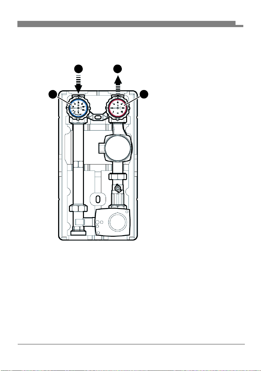
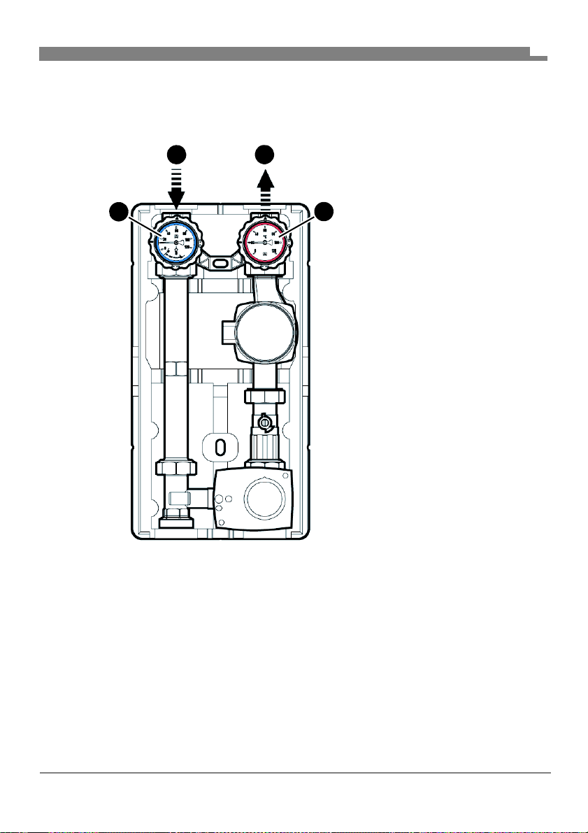
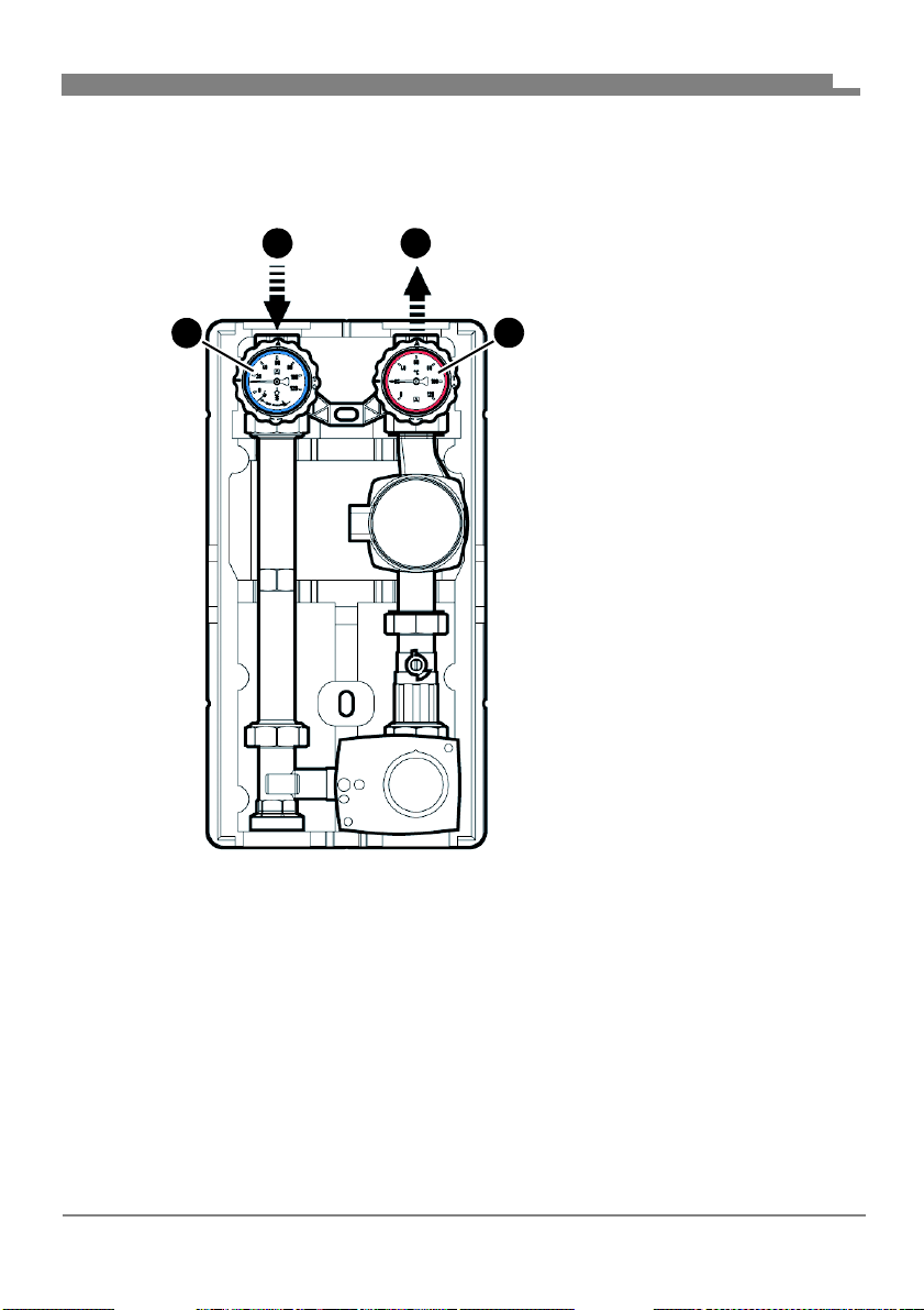
5.1.1 Interchanging flow/return
Unless otherwise specified, all information in these operating instructions
relates to the installation type "flow right".
EN
A. Return
B. Flow
C. Red thermometer ball
valve
D. Blue thermometer ball
valve
Fig. 5: Flow right (condition as supplied)
FA PG - 06/2019 - 008.15 442 99_02 - EN
14
Page 17
Mounting
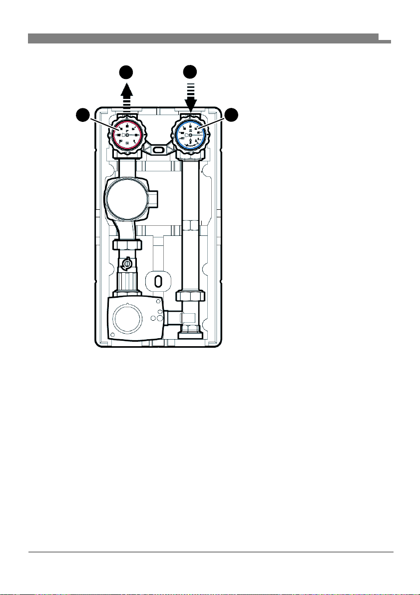
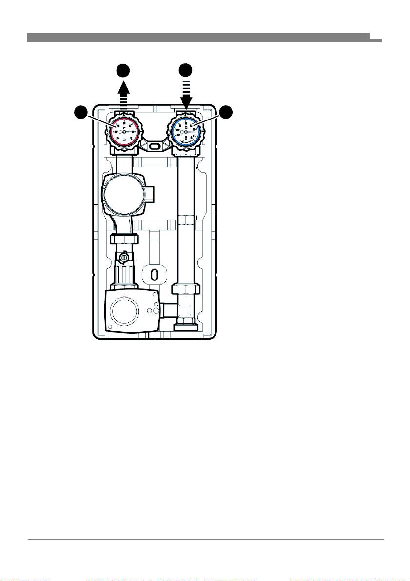
D
A
A
B
C
D
EN
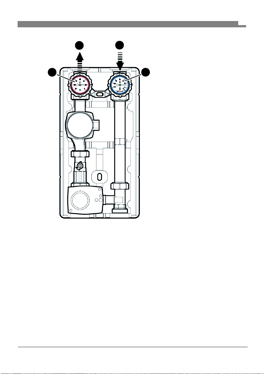
A. Flow
B. Return
C. Blue thermometer ball
valve
D. Red thermometer ball
valve
Fig. 6: Flow left
FA PG - 06/2019 - 008.15 442 99_02 - EN
15
Page 18
Mounting
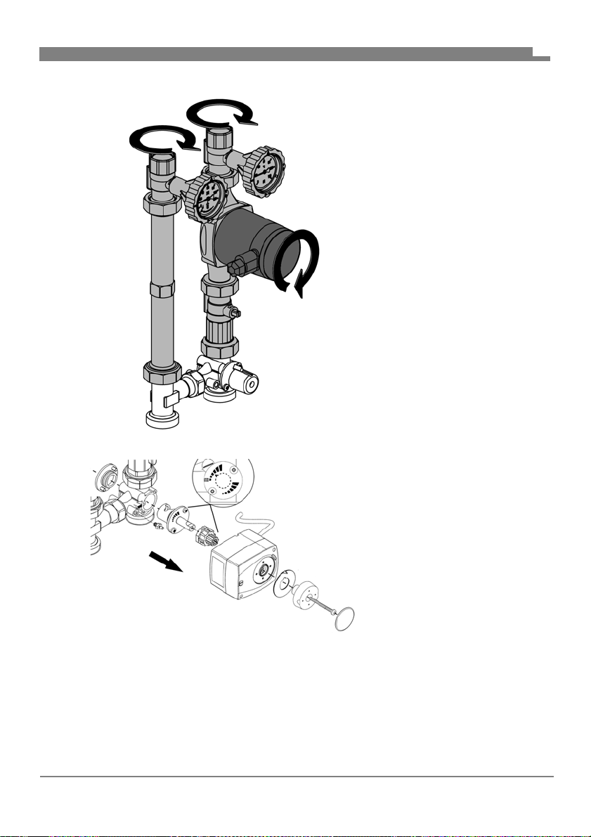
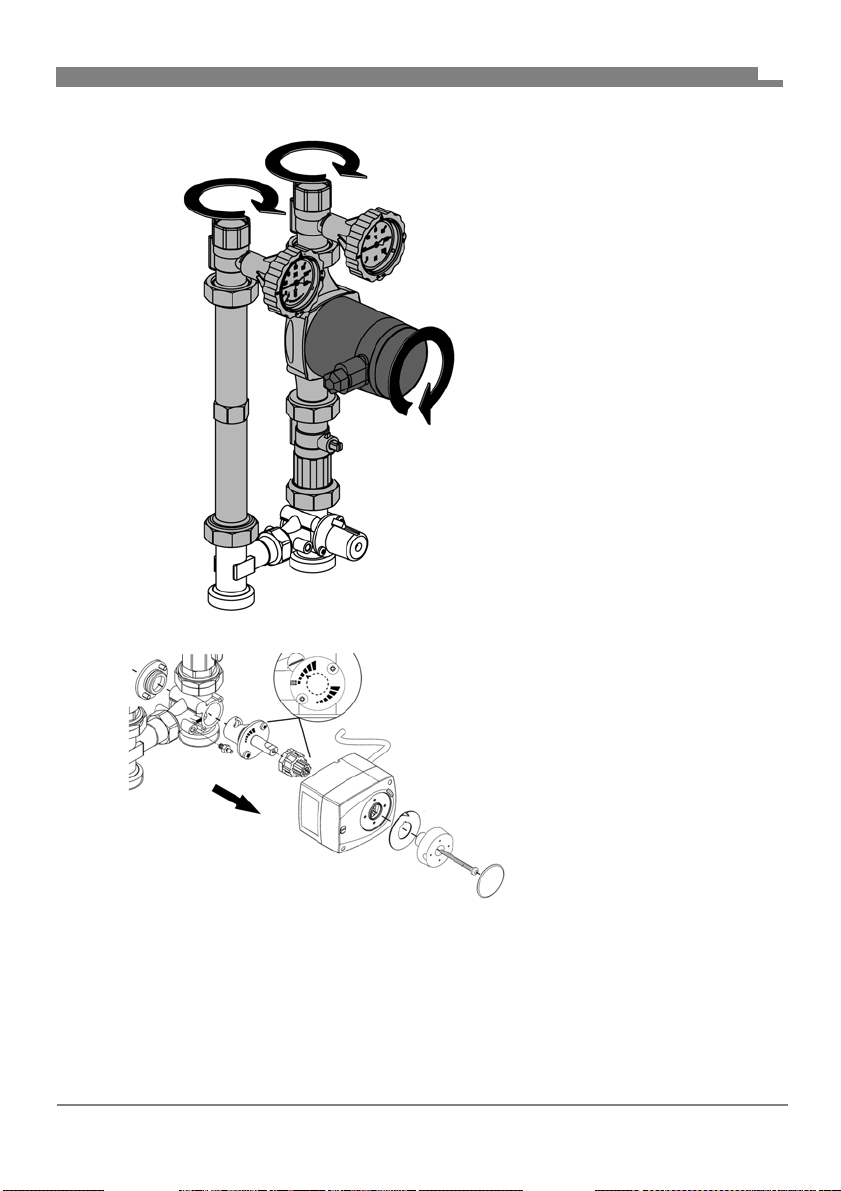
EN
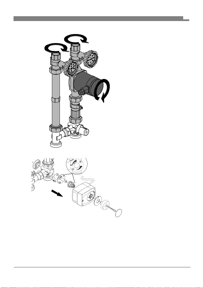
1. Interchange left and right
lines.
2. Turn the pump head.
3. Change the actuator.
- Flow right
4. Uninstall the actuator.
FA PG - 06/2019 - 008.15 442 99_02 - EN
16
Page 19
Mounting
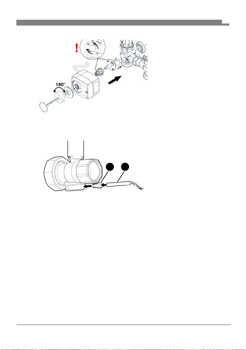
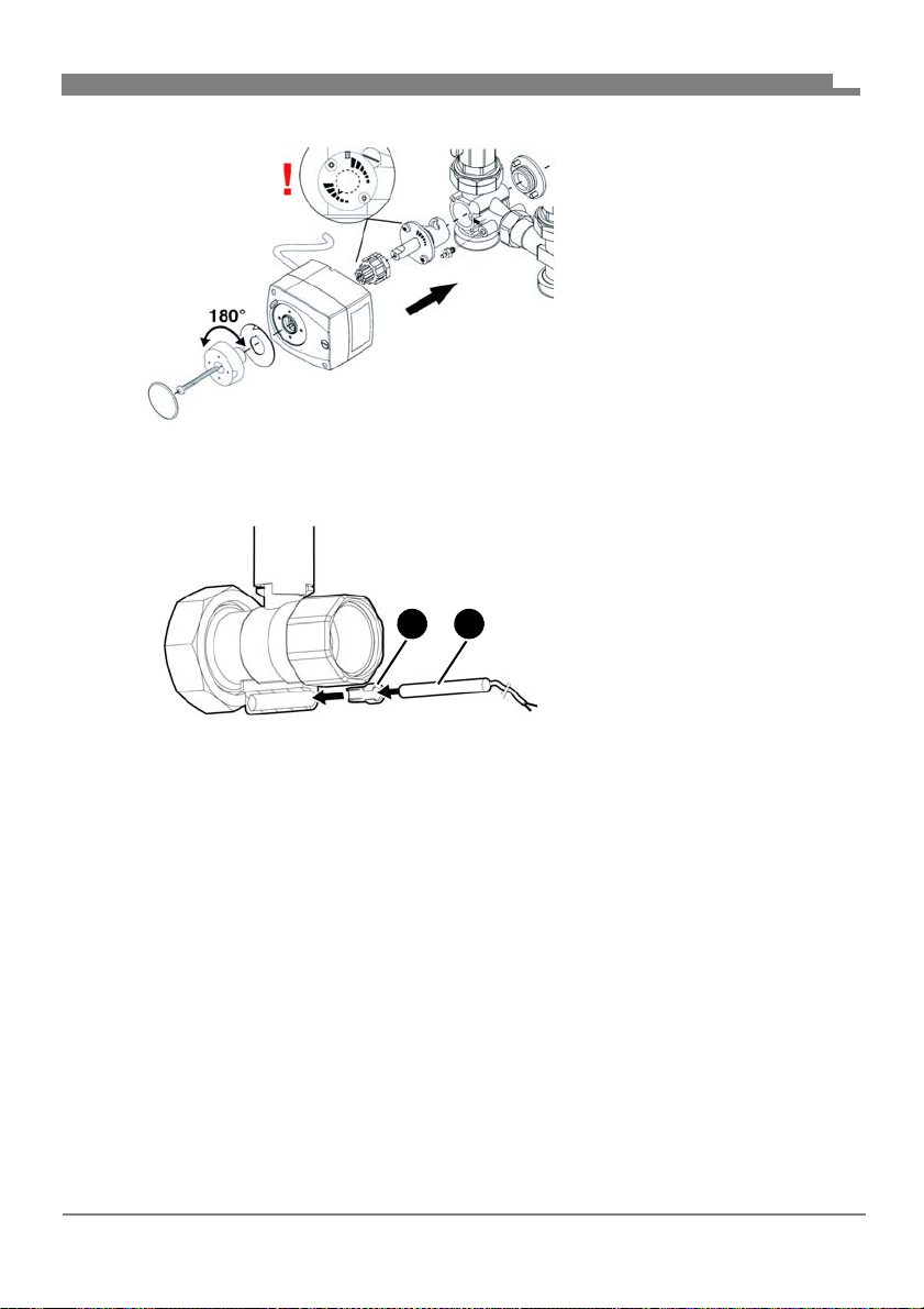
A B
5. Re-install the actuator.
- Flow left
6. Fit the upper insulation.
5.1.2 Mounting the temperature probe (optional)
Depending on the type of the
temperature probe (B), it may
be necessary to shorten the
ferrule (A).
EN
FA PG - 06/2019 - 008.15 442 99_02 - EN
17
Page 20

Mounting
5.2 Mounting the product
5.2.1 Mounting the product to a module manifold
NOTICE
MECHANICAL LOADS AND STRESS
• Verify that the product is not subjected to mechanical loads and stress when
connecting the product.
• If necessary, install a corrugated pipe compensator to compensate for
mechanical stress or tension.
Failure to follow these instructions can result in equipment damage.
1. Remove the insulation.
2. Screw the pump assembly to module manifold.
3. Screw the pipes of the heating circuit to the top connections (no
mechanical stress).
4. Fit the complete insulation.
5.2.2 Wall mounting
EN
NOTICE
MECHANICAL LOADS AND STRESS
• Verify that the product is not subjected to mechanical loads and stress when
mounting the product to the wall.
Failure to follow these instructions can result in equipment damage.
FA PG - 06/2019 - 008.15 442 99_02 - EN
18
Page 21
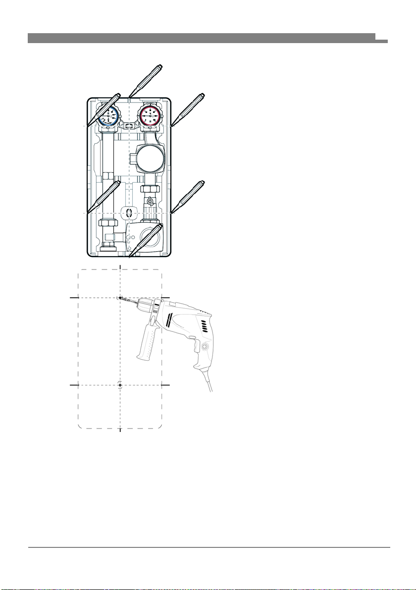
Mounting
EN
1. Remove the upper insulation.
2. Hold the product to the wall and
align it with a level.
3. Draw six marks.
4. Interconnect the opposing marks.
5. Drill holes (Ø 10 mm) at the position of the two centre marks.
6. Insert the enclosed dowels.
7. Screw the long hanger bolt into
the top hole.
8. Screw the short hanger bolt into
the bottom hole.
9. Fit the product with the bottom insulation and secure it with a washer and
a nut.
10.Connect the pipes of the heating circuit to the connections of the fittings
(no mechanical stress).
11.Fit the upper insulation.
FA PG - 06/2019 - 008.15 442 99_02 - EN
19
Page 22
Mounting
5.3 Electrical connection
DANGER
ELECTRIC SHOCK
• Verify that the degree of protection against electric shock (protection class,
double insulation) is not reduced by the type of electrical installation.
Failure to follow these instructions will result in death or serious injury.
DANGER
ELECTRIC SHOCK CAUSED BY LIVE PARTS
• Disconnect the mains voltage supply before performing the work and ensure
that it cannot be switched on.
• Verify that no hazards can be caused by electrically conductive objects or
media.
Failure to follow these instructions will result in death or serious injury.
1. Connect the circulation pump and the actuator in accordance with the
instructions of the manufacturer.
EN
FA PG - 06/2019 - 008.15 442 99_02 - EN
20
Page 23
Commissioning
6 Commissioning
6.1 Commissioning the product
Verify that the thermometer ball valves are in 0° setting.
1. Perform a pressure test.
2. Check all screwed connections for tightness.
3. Set to ball valves to 45° position for filling of the system.
4. Fill the system and apply pressure.
5. Set the ball valves to 0° position.
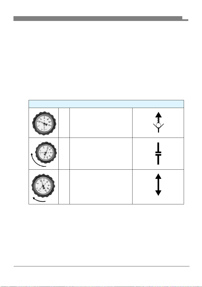
6.1.1 Thermometer ball valves
Thermometer ball valves
0° Normal operation:
Gravity brake active
90 ° Maintenance:
Ball valve closed
EN
45 ° Commissioning, filling, vent-
ing, flushing:
Both ends open (gravity
brake not active)
7 Operation
Proper operation is only possible if the thermometer ball valves and the ball
valves are open (0° setting, see chapter "Thermometer ball valves").
FA PG - 06/2019 - 008.15 442 99_02 - EN
21
Page 24
Maintenance
8 Maintenance
8.1 Maintenance intervals
When Activity
Monthly Perform a visual inspection of the heating system
and verify tightness.
If required Replace the circulation pump.
8.2 Maintenance activities
DANGER
ELECTRIC SHOCK CAUSED BY LIVE PARTS
• Disconnect the mains voltage supply before performing the work and ensure
that it cannot be switched on.
Failure to follow these instructions will result in death or serious injury.
8.2.1 Replacing a defective circulation pump
1. Close the red thermometer ball valve and the ball valve in the pump line
(90° setting).
2. Replace the circulation pump (see instructions of the manufacturer of
the pump).
3. Open the thermometer ball valve and the ball valve (0° setting).
EN
FA PG - 06/2019 - 008.15 442 99_02 - EN
22
Page 25

Troubleshooting
9 Troubleshooting
Any malfunctions that cannot be removed by means of the measures
described in this chapter may only be repaired by the manufacturer.
Also observe the corresponding instructions of the manufacturer in the case
of malfunctions of the circulation pump or the actuator.
Problem Possible reason Repair
Noise in the system Air in the system Vent the system
Circulation pump not
properly adjusted
Other malfunctions - Contact the AFRISO
Verify correct adjustment of the circulation
pump
service hotline
EN
FA PG - 06/2019 - 008.15 442 99_02 - EN
23
Page 26

Decommissioning, disposal
10 Decommissioning, disposal
Dispose of the product in compliance with all applicable directives, standards
and safety regulations.
Electronic components must not be disposed of together with the normal
household waste.
1. Disconnect the product from mains.
2. Dismount the product (see chapter "Mounting", reverse
sequence of steps).
3. Dispose of the product.
11 Returning the device
Get in touch with us before returning your product.
12 Warranty
See our terms and conditions at www.daikin.com or your purchase contract
for information on warranty.
EN
FA PG - 06/2019 - 008.15 442 99_02 - EN
24
Page 27

__________________________
__________________________
__________________________
__________________________
__________________________
__________________________
__________________________
__________________________
__________________________
__________________________
__________________________
__________________________
__________________________
__________________________
__________________________
__________________________
__________________________
__________________________
__________________________
__________________________
__________________________
__________________________
__________________________
__________________________
__________________________
__________________________
__________________________
__________________________
__________________________
__________________________
__________________________
__________________________
__________________________
__________________________
__________________________
__________________________
__________________________
__________________________
__________________________
__________________________
__________________________
__________________________
__________________________
__________________________
__________________________
__________________________
__________________________
__________________________
__________________________
__________________________
__________________________
__________________________
__________________________
__________________________
__________________________
__________________________
__________________________
__________________________
__________________________
__________________________
__________________________
__________________________
__________________________
__________________________
__________________________
__________________________
__________________________
__________________________
__________________________
__________________________
__________________________
Page 28

Page 29
156077 PGDK
156075 PGMK
Vor Gebrauch lesen!
Deutsch
Alle Sicherheitshinwei
se beachten!
Für künftige Verwendung aufbewahren!
Page 30

Über diese Betriebsanleitung
1 Über diese Betriebsanleitung
Diese Betriebsanleitung beschreibt die Pumpengruppe mit und ohne
Mischer (im folgenden auch „Produkt“).
Diese Betriebsanleitung ist Teil des Produkts.
• Sie dürfen das Produkt erst benutzen, wenn Sie die Betriebsanleitung
vollständig gelesen und verstanden haben.
• Stellen Sie sicher, dass die Betriebsanleitung für alle Arbeiten an und mit
dem Produkt jederzeit verfügbar ist.
• Geben Sie die Betriebsanleitung und alle zum Produkt gehörenden
Unterlagen an alle Benutzer des Produkts weiter.
• Wenn Sie der Meinung sind, dass die Betriebsanleitung Fehler, Widersprüche oder Unklarheiten enthält, wenden Sie sich vor Benutzung des
Produkts an den Hersteller.
Diese Betriebsanleitung ist urheberrechtlich geschützt und darf ausschließlich im rechtlich zulässigen Rahmen verwendet werden. Änderungen vorbehalten.
Für Schäden und Folgeschäden, die durch Nichtbeachtung dieser Betriebsanleitung sowie Nichtbeachten der am Einsatzort des Produkts geltenden
Vorschriften, Bestimmungen und Normen entstehen, übernimmt der Hersteller keinerlei Haftung oder Gewährleistung.
DE
FA PG - 06/2019 - 008.15 442 99_02 - DE
2
Page 31
Informationen zur Sicherheit
2 Informationen zur Sicherheit
2.1 Warnhinweise und Gefahrenklassen
In dieser Betriebsanleitung finden Sie Warnhinweise, die auf potenzielle
Gefahren und Risiken aufmerksam machen. Zusätzlich zu den Anweisungen
in dieser Betriebsanleitung müssen Sie alle am Einsatzort des Produktes
geltenden Bestimmungen, Normen und Sicherheitsvorschriften beachten.
Stellen Sie vor Verwendung des Produktes sicher, dass Ihnen alle Bestimmungen, Normen und Sicherheitsvorschriften bekannt sind und dass sie
befolgt werden.
Warnhinweise sind in dieser Betriebsanleitung mit Warnsymbolen und Signalwörtern gekennzeichnet. Abhängig von der Schwere einer Gefährdungssituation werden Warnhinweise in unterschiedliche Gefahrenklassen unterteilt.
GEFAHR
GEFAHR macht auf eine unmittelbar gefährliche Situation aufmerksam, die
bei Nichtbeachtung unweigerlich einen schweren oder tödlichen Unfall zur
Folge hat.
DE
WARNUNG
WARNUNG macht auf eine möglicherweise gefährliche Situation aufmerksam, die bei Nichtbeachtung einen schweren oder tödlichen Unfall oder
Sachschäden zur Folge haben kann.
HINWEIS
HINWEIS macht auf eine möglicherweise gefährliche Situation aufmerksam,
die bei Nichtbeachtung Sachschäden zur Folge haben kann.
FA PG - 06/2019 - 008.15 442 99_02 - DE
3
Page 32
Informationen zur Sicherheit
Zusätzlich werden in dieser Betriebsanleitung folgende Symbole verwendet:
Dies ist das allgemeine Warnsymbol. Es weist auf die
Gefahr von Verletzungen und Sachschäden hin. Befolgen
Sie alle im Zusammenhang mit diesem Warnsymbol
beschriebenen Hinweise, um Unfälle mit Todesfolge, Verletzungen und Sachschäden zu vermeiden.
Dieses Symbol warnt vor gefährlicher elektrischer Spannung. Wenn dieses Symbol in einem Warnhinweis gezeigt
wird, besteht die Gefahr eines elektrischen Schlags.
2.2 Bestimmungsgemäße Verwendung
Dieses Produkt eignet sich ausschließlich zum Umwälzen folgender Medien
in eigensicheren, geschlossenen thermischen Heizungsanlagen:
• Heizungswasser nach VDI 2035
• Wasser-Glykol-Gemische mit maximal 20 % Beimischung
Eine andere Verwendung ist nicht bestimmungsgemäß und verursacht
Gefahren.
Stellen Sie vor Verwendung des Produkts sicher, dass das Produkt für die
von Ihnen vorgesehene Verwendung geeignet ist. Berücksichtigen Sie dabei
mindestens folgendes:
• Alle am Einsatzort geltenden Bestimmungen, Normen und Sicherheitsvorschriften
• Alle für das Produkt spezifizierten Bedingungen und Daten
• Die Bedingungen der von Ihnen vorgesehenen Anwendung
Führen Sie darüber hinaus eine Risikobeurteilung in Bezug auf die konkrete,
von Ihnen vorgesehene Anwendung nach einem anerkannten Verfahren
durch und treffen Sie entsprechende dem Ergebnis alle erforderlichen
Sicherheitsmaßnahmen. Berücksichtigen Sie dabei auch die möglichen Folgen eines Einbaus oder einer Integration des Produkts in ein System oder in
eine Anlage.
Führen Sie bei der Verwendung des Produkts alle Arbeiten ausschließlich
unter den in der Betriebsanleitung und auf dem Typenschild spezifizierten
Bedingungen und innerhalb der spezifizierten technischen Daten und in
Übereinstimmung mit allen am Einsatzort geltenden Bestimmungen, Normen und Sicherheitsvorschriften durch.
DE
FA PG - 06/2019 - 008.15 442 99_02 - DE
4
Page 33

Informationen zur Sicherheit
2.3 Vorhersehbare Fehlanwendung
Das Produkt darf insbesondere in folgenden Fällen und für folgende Zwecke
nicht angewendet werden:
• Betrieb mit Trinkwasser
• Betrieb mit verklebenden, ätzenden oder entzündlichen Medien
• Betrieb in Anlagen mit Temperaturen über 110 °C
beispielsweise Solaranlagen)
2.4 Qualifikation des Personals
Arbeiten an und mit diesem Produkt dürfen nur von Fachkräften vorgenommen werden, die den Inhalt dieser Betriebsanleitung und alle zum Produkt
gehörenden Unterlagen kennen und verstehen.
Die Fachkräfte müssen aufgrund ihrer fachlichen Ausbildung, Kenntnisse
und Erfahrungen in der Lage sein, mögliche Gefährdungen vorherzusehen
und zu erkennen, die durch den Einsatz des Produkts entstehen können.
Den Fachkräften müssen alle geltenden Bestimmungen, Normen und
Sicherheitsvorschriften, die bei Arbeiten an und mit dem Produkt beachtet
werden müssen, bekannt sein.
2.5 Persönliche Schutzausrüstung
Verwenden Sie immer die erforderliche persönliche Schutzausrüstung.
Berücksichtigen Sie bei Arbeiten an und mit dem Produkt auch, dass am Einsatzort Gefährdungen auftreten können, die nicht direkt vom Produkt ausgehen.
DE
2.6 Veränderungen am Produkt
Führen Sie ausschließlich solche Arbeiten an und mit dem Produkt durch, die
in dieser Betriebsanleitung beschrieben sind. Nehmen Sie keine Veränderungen vor, die in dieser Betriebsanleitung nicht beschrieben sind.
FA PG - 06/2019 - 008.15 442 99_02 - DE
5
Page 34

Transport und Lagerung
3 Transport und Lagerung
Das Produkt kann durch unsachgemäßen Transport und Lagerung beschädigt werden.
HINWEIS
BESCHÄDIGUNG DES PRODUKTS
• Stellen Sie sicher, dass während des Transports und der Lagerung des Produkts die spezifizierten Umgebungsbedingungen eingehalten werden.
• Benutzen Sie für den Transport die Originalverpackung.
• Lagern Sie das Produkt nur in trockener, sauberer Umgebung.
• Stellen Sie sicher, dass das Produkt bei Transport und Lagerung stoßgeschützt ist.
Nichtbeachtung dieser Anweisungen kann zu Sachschäden führen.
DE
FA PG - 06/2019 - 008.15 442 99_02 - DE
6
Page 35

Produktbeschreibung
4 Produktbeschreibung
Das Produkt ist eine vormontierte, dichtheitsgeprüfte und wärmegedämmte
Pumpengruppe.
Die universelle Isolation erlaubt den Einbau nahezu jeder handelsüblichen
Umwälzpumpe (mit Anschluss G1
großes Nachbearbeiten.
Der zweite Kugelhahn im Rücklaufstrang erlaubt einen Pumpentausch ohne
Entleeren der Anlage.
Das modulare System ermöglicht zudem die Anordnung des Vorlaufs wahlweise links oder rechts. Optional können in allen Kugelhähnen Temperaturfühler Ø 6 mm montiert werden.
1
/
und einer Baulänge von 180 mm) ohne
2
DE
FA PG - 06/2019 - 008.15 442 99_02 - DE
7
Page 36
4.1 Übersicht
1
2
B
C
D
E
F
A
Produktbeschreibung
1. Rücklauf
2. Vorlauf
A. Kugelhahn, absperrbar,
B. Kugelhahn, absperrbar,
C. Umwälzpumpe (verschie-
D. Kugelhahn
E. 3-Wege-Mischer mit Stell-
F. Isolation
DE
mit Thermometer blau
und Schwerkraftbremse
mit Thermometer rot
dene Hersteller)
motor
Abbildung 1: PrimoTherm® Komponenten
FA PG - 06/2019 - 008.15 442 99_02 - DE
8
Page 37
Produktbeschreibung
4.2 Varianten
Die variable Isolation ist für den Einsatz mit Vorlauf links oder Vorlauf rechts
einsetzbar.
Abbildung 2: Vorlauf rechts (Abbildung links)
Abbildung 3: Vorlauf links (Abbildung mitte)
Abbildung 4: Ohne Stellmotor (Abbildung rechts)
DE
FA PG - 06/2019 - 008.15 442 99_02 - DE
9
Page 38
Produktbeschreibung
ca. 250 mm
ca. 175 mm
ca. 475 mm
ca. 152 mm
4.3 Abmessungen und Anschlüsse
DE
FA PG - 06/2019 - 008.15 442 99_02 - DE
10
Page 39
Produktbeschreibung
B
1
B
B
A
ca. 125 mm
ca. 60 mm
A. G1
B. G1½
DE
4.4 Zulassungsdokumente, Bescheinigungen, Erklärungen
Bei Ausführung mit Umwälzpumpe, siehe Anleitung des Pumpenherstellers.
FA PG - 06/2019 - 008.15 442 99_02 - DE
11
Page 40
Produktbeschreibung
4.5 Technische Daten
Parameter Wert
Allgemeine Daten
Abmessungen mit Isolation
(B x H x T)
Gewicht Ca. 5,5 kg mit Mischer
Werkstoff Armaturen Messing
Werkstoff Isolation Polypropylen EPP
Anlagendruck Max. 10 bar
Achsabstand 125 mm
Systemanschlüsse Kessel R1
Kvs-Wert 4,8 m
Temperatureinsatzbereich
Medium Max. 110 °C
Druckverlust
Vorlaufstrang Kvs = 6,9 m
Rücklaufstrang Kvs = 6,7 m
Gesamt Kvs = 4,8 m
250 x 475 x 152 mm
Ca. 7,2 kg ohne Mischer
(Maximaldruck der verwendeten
Umwälzpumpe beachten)
1
/
2
Heizkreis Rp1
3
/h
3
/h
3
/h
3
/h
DE
FA PG - 06/2019 - 008.15 442 99_02 - DE
12
Page 41

Montage
5 Montage
WARNUNG
VERBRENNUNGEN DURCH HEISSE FLÜSSIGKEIT
Wasser in Heizungsanlagen steht unter einem hohen Druck und kann Temperaturen bis über 100 °C erreichen.
• Stellen Sie sicher, dass das Heizwasser abgekühlt ist, bevor Sie die Anlage
öffnen und das Produkt montieren.
Nichtbeachtung dieser Anweisung kann zu Tod, schweren Verletzungen
oder Sachschäden führen.
5.1 Montage vorbereiten
Stellen Sie sicher, dass das Produkt so montiert ist, dass im eingebautem
Zustand keine äußeren Kräfte auf die Armaturen einwirken.
Stellen Sie sicher, dass das Produkt vor Schweiß- und Lötarbeiten an der
Anlage nicht überhitzt wird.
- Das Produkt erst nach diesen Arbeiten einbauen.
Stellen Sie sicher, dass der Nenndruck des Produkts dem Planwert der
Anlage entspricht.
Stellen Sie sicher, dass die Flüssigkeit in der Anlage mit dem Einsatzbe-
reich des Produkts verträglich ist.
Stellen Sie sicher, dass die Leitung des Produkts vor der Montage gut
durch gespült ist.
- Verunreinigungen wie Schweißperlen, Hanf oder Metallspäne machen
das Produkt undicht.
DE
FA PG - 06/2019 - 008.15 442 99_02 - DE
13
Page 42
Montage
B
A
C
B
D
5.1.1 Vorlauf/Rücklauf tauschen
Falls nicht anders angegeben, beziehen sich alle Angaben in dieser
Betriebsanleitung auf die Einbauweise „Vorlauf rechts“.
DE
A. Rücklauf
B. Vorlauf
C. Roter Thermometer-
Kugelhahn
D. Blauer Thermometer-
Kugelhahn
Abbildung 5: Vorlauf rechts (Auslieferungszustand)
FA PG - 06/2019 - 008.15 442 99_02 - DE
14
Page 43
Montage
D
A
A
B
C
D
DE
A. Vorlauf
B. Rücklauf
C. Blauer Thermometer-
Kugelhahn
D. Roter Thermometer-
Kugelhahn
Abbildung 6: Vorlauf links
FA PG - 06/2019 - 008.15 442 99_02 - DE
15
Page 44
Montage
DE
1. Tauschen Sie den linken
und den rechten Strang.
2. Drehen Sie den Pumpenkopf.
3. Wechseln Sie den Stellmotor.
- Vorlauf rechts
4. Bauen Sie den Stellmotor
aus.
FA PG - 06/2019 - 008.15 442 99_02 - DE
16
Page 45
Montage
A B
5. Bauen Sie den Stellmotor
6. Setzen Sie die obere Iso-
5.1.2 Temperaturfühler montieren (optional)
Je nach Typ des Temperaturfühlers (B) kann es nötig sein
die Klemmhülse (A) zu kürzen.
DE
ein.
- Vorlauf links
lation auf.
FA PG - 06/2019 - 008.15 442 99_02 - DE
17
Page 46

Montage
5.2 Produkt montieren
5.2.1 Produkt auf Modulverteiler montieren
HINWEIS
MECHANISCHE BELASTUNG UND VERSPANNUNG
• Stellen Sie beim Anschließen des Produkts sicher, dass das Produkt keinen
mechanischen Belastungen und Verspannungen ausgesetzt ist.
• Bauen Sie, wenn erforderlich, einen Wellrohrkompensator ein, um mechanische Belastungen und Verspannungen zu kompensieren.
Nichtbeachtung dieser Anweisungen kann zu Sachschäden führen.
1. Entfernen Sie die Isolation.
2. Schrauben Sie die Pumpengruppe auf den Modulverteiler.
3. Verschrauben Sie die Rohrleitungen des Heizkreises mit den oberen
Anschlüsse spannungsfrei.
4. Setzten Sie die komplette Isolation auf.
5.2.2 Wandmontage
DE
HINWEIS
MECHANISCHE BELASTUNG UND VERSPANNUNG
• Stellen Sie bei der Montage des Produkts an der Wand sicher, dass das Produkt keinen mechanischen Belastungen und Verspannungen ausgesetzt ist.
Nichtbeachtung dieser Anweisungen kann zu Sachschäden führen.
FA PG - 06/2019 - 008.15 442 99_02 - DE
18
Page 47
Montage
DE
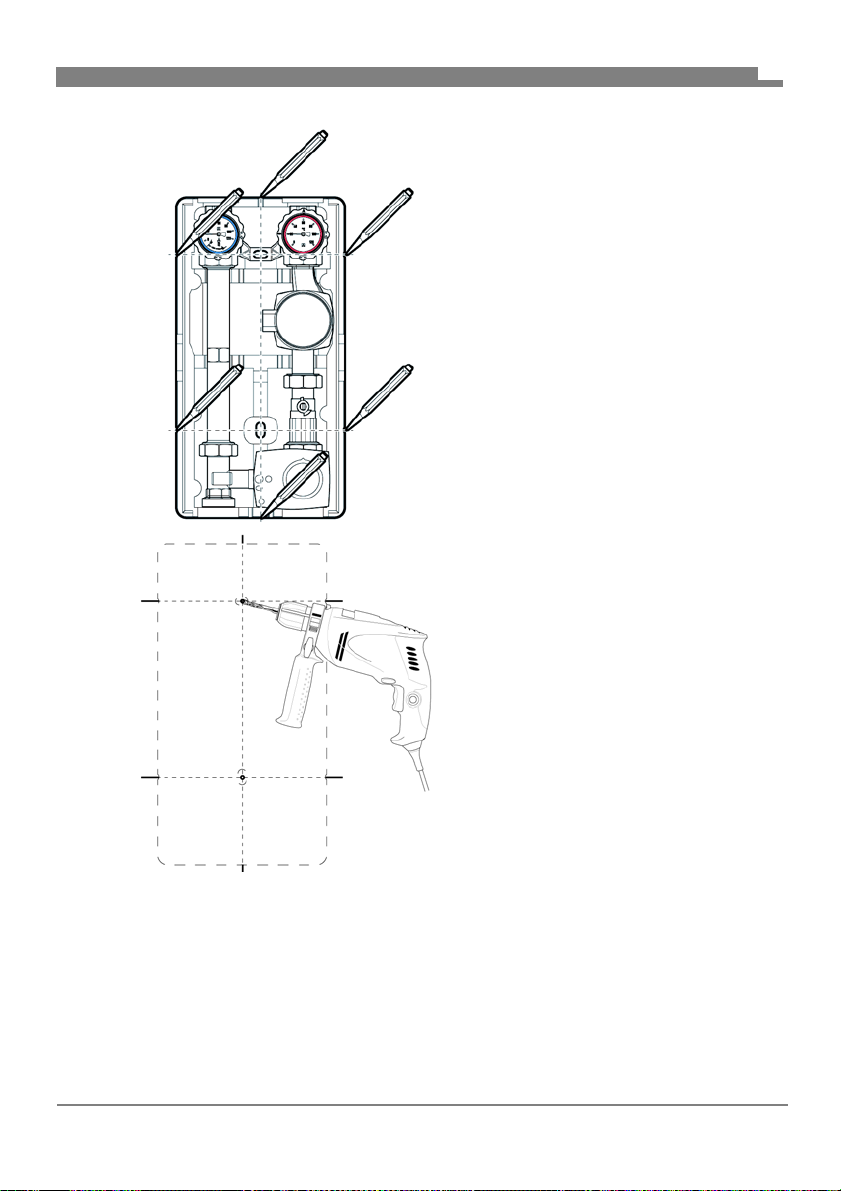
1. Entfernen Sie die obere Isolation.
2. Heben Sie das Produkt an die
Wand und richten es mit einer
Wasserwaage aus.
3. Zeichnen Sie sechs Markierungen an.
4. Verbinden Sie die gegenüberliegenden Markierungen miteinander.
5. Bohren Sie an der mittleren Markierungen jeweils ein Loch
(Ø 10 mm).
6. Führen Sie die beiliegenden
Dübel ein.
7. Drehen Sie die lange Stockschraube oben ein.
8. Drehen Sie die kurze Stockschraube unten ein.
9. Hängen Sie das Produkt mit der unteren Isolation ein und sichern Sie das
Produkt mit Unterlegscheibe und Mutter.
10.Verbinden und verschrauben Sie die Rohrleitungen des Heizkreises mit
den Anschlüssen der Armaturen spannungsfrei.
11.Setzten Sie die obere Isolation auf.
FA PG - 06/2019 - 008.15 442 99_02 - DE
19
Page 48
Montage
5.3 Elektrischer Anschluss
GEFAHR
ELEKTRISCHER SCHLAG
• Stellen Sie sicher, dass durch die Art der elektrischen Installation der Schutz
gegen elektrischen Schlag (Schutzklasse, Schutzisolierung) nicht vermindert wird.
Nichtbeachtung dieser Anweisungen führt zu Tod oder schweren Verletzungen.
GEFAHR
ELEKTRISCHER SCHLAG DURCH SPANNUNGSFÜHRENDE TEILE
• Unterbrechen Sie vor Beginn der Arbeiten die Netzspannung und sichern
Sie diese gegen Wiedereinschalten.
• Stellen Sie sicher, dass durch elektrisch leitfähige Gegenstände oder
Medien keine Gefährdungen ausgehen können.
Nichtbeachtung dieser Anweisungen führt zu Tod oder schweren Verletzungen.
DE
1. Schließen Sie die Umwälzpumpe und den Stellmotor nach der jeweiligen
Anleitung des Herstellers an.
FA PG - 06/2019 - 008.15 442 99_02 - DE
20
Page 49
Inbetriebnahme
6 Inbetriebnahme
6.1 Produkt in Betrieb nehmen
Stellen Sie sicher, dass die Thermometer-Kugelhähne in 0°-Stellung sind.
1. Führen Sie eine Druckprobe durch.
2. Prüfen Sie alle Verschraubungen auf Dichtheit.
3. Bringen Sie zum Befüllen der Anlage die Kugelhähne in 45°-Stellung.
4. Befüllen Sie die Anlage und beaufschlagen Sie die Anlage mit Druck.
5. Bringen Sie die Kugelhähne in 0°-Stellung.
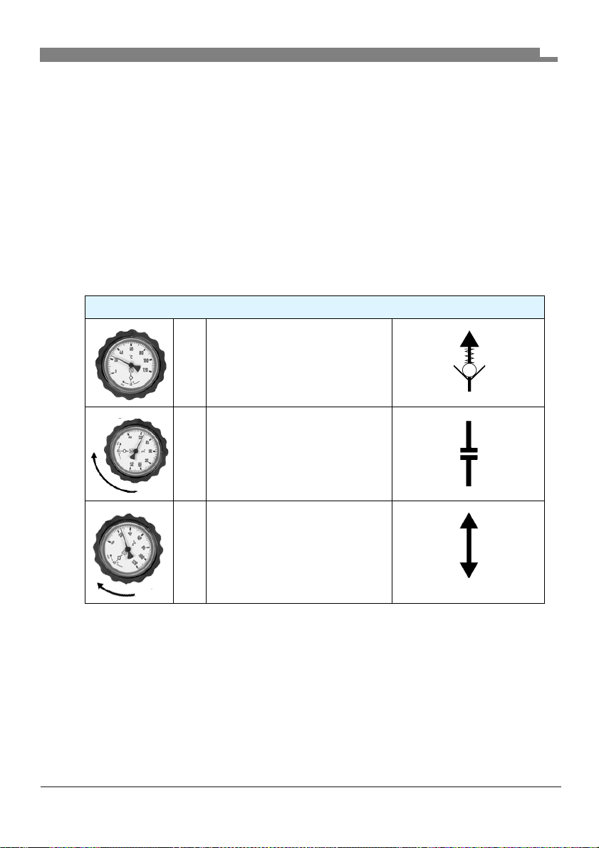
6.1.1 Thermometer-Kugelhähne
Thermometer-Kugelhähne
0° Normalbetrieb:
Schwerkraftbremse aktiviert
90 ° Wartung:
Kugelhahn geschlossen
DE
45 ° Inbetriebnahme, Befüllen,
Entlüften, Spülen:
Beide Seiten offen (die
Schwerkraftbremse ist deaktiviert)
7 Betrieb
Ein einwandfreier Betrieb ist nur bei offenen Thermometer-Kugelhähnen und
Kugelhähnen möglich (0°-Stellung, siehe Kapitel "Thermometer-Kugelhähne").
FA PG - 06/2019 - 008.15 442 99_02 - DE
21
Page 50
Wartung
8 Wartung
8.1 Wartungsintervall
Zeitpunkt Tätigkeit
1 x monatlich Prüfen Sie die Heizungsanlage visuell auf
Undichtigkeit.
Bei Bedarf Tauschen Sie die Umwälzpumpe aus.
8.2 Wartungstätigkeiten
GEFAHR
ELEKTRISCHER SCHLAG DURCH SPANNUNGSFÜHRENDE TEILE
• Unterbrechen Sie vor Beginn der Arbeiten die Netzspannung und sichern
Sie diese gegen Wiedereinschalten.
Nichtbeachtung dieser Anweisungen führt zu Tod oder schweren Verletzungen.
8.2.1 Defekte Umwälzpumpe austauschen
1. Schließen Sie den roten Thermometer-Kugelhahn und den Kugelhahn
im Pumpenstrang (90°-Stellung).
2. Tauschen Sie die Umwälzpumpe aus
(Siehe Anleitung des Pumpenherstellers).
3. Öffnen Sie den Thermometer-Kugelhahn und den Kugelhahn wieder
(0°-Stellung).
DE
FA PG - 06/2019 - 008.15 442 99_02 - DE
22
Page 51

Störungsbeseitigung
9 Störungsbeseitigung
Störungen, die nicht durch die im Kapitel beschriebenen Maßnahmen beseitigt werden können, dürfen nur durch den Hersteller behoben werden.
Bitte beachten Sie bei Störungen an der Umwälzpumpe oder des Stellmotors
zusätzlich die jeweilige Anleitung des Herstellers.
Problem Mögliche Ursache Fehlerbehebung
Anlage macht Geräusche
Sonstige Störungen - Bitte wenden Sie sich
Luft in der Anlage Entlüften Sie die Anlage
Umwälzpumpe ist falsch
eingestellt
Überprüfen Sie die Einstellung der Umwälzpumpe
an die AFRISO-Service
Hotline
DE
FA PG - 06/2019 - 008.15 442 99_02 - DE
23
Page 52

Außerbetriebnahme und Entsorgung
10 Außerbetriebnahme und Entsorgung
Entsorgen Sie das Produkt nach den geltenden Bestimmungen, Normen und
Sicherheitsvorschriften.
Elektronikteile dürfen nicht mit dem Hausmüll entsorgt werden.
1. Trennen Sie das Produkt von der Versorgungsspannung.
2. Demontieren Sie das Produkt (siehe Kapitel "Montage"
in umgekehrter Reihenfolge).
3. Entsorgen Sie das Produkt.
11 Rücksendung
Vor einer Rücksendung Ihres Produkts müssen Sie sich mit uns in Verbindung setzen.
12 Gewährleistung
Informationen zur Gewährleistung finden Sie in unseren Allgemeinen
Geschäftsbedingungen im Internet unter www.daikin.com oder in Ihrem
Kaufvertrag.
DE
FA PG - 06/2019 - 008.15 442 99_02 - DE
24
Page 53

__________________________
__________________________
__________________________
__________________________
__________________________
__________________________
__________________________
__________________________
__________________________
__________________________
__________________________
__________________________
__________________________
__________________________
__________________________
__________________________
__________________________
__________________________
__________________________
__________________________
__________________________
__________________________
__________________________
__________________________
__________________________
__________________________
__________________________
__________________________
__________________________
__________________________
__________________________
__________________________
__________________________
__________________________
__________________________
__________________________
__________________________
__________________________
__________________________
__________________________
__________________________
__________________________
__________________________
__________________________
__________________________
__________________________
__________________________
__________________________
__________________________
__________________________
__________________________
__________________________
__________________________
__________________________
__________________________
__________________________
__________________________
__________________________
__________________________
__________________________
__________________________
__________________________
__________________________
__________________________
__________________________
__________________________
__________________________
__________________________
__________________________
__________________________
__________________________
Page 54

Page 55
156077 PGDK
156075 PGMK
Lire la notice avant la mise en route!
Respecter les consignes de sécurité!
Conserver la notice technique pour une utilisation ultérieure!
Français
Page 56

La présente notice technique
1 La présente notice technique
Cette notice technique contient la description du groupe de pompe avec
mélangeur et sans mélangeur (dénommé ci-après "produit").
Cette notice technique fait partie du produit.
• Utilisez le produit seulement après que vous aurez lu et compris intégralement la notice technique.
• Assurez-vous que la notice technique est disponible en permanence pour
toutes les opérations relatives au produit.
• Transmettez la notice technique et toute la documentation relative au produit à tous les utilisateurs du produit.
• Si vous êtes d'avis que la notice technique contient des erreurs, des
contradictions ou des ambiguïtés, adressez-vous au fabricant avant d'utiliser le produit.
Cette notice technique est protégée au titre de la propriété intellectuelle ; elle
doit être utilisée exclusivement dans le cadre autorisé par la loi. Sous réserve
de modifications.
La responsabilité du fabricant ou la garantie ne pourra être engagée pour des
dommages ou dommages consécutifs résultant d'une inobservation des
directives, règlements et normes en vigueur sur le lieu d'installation du produit.
FR
FA PG - 06/2019 - 008.15 442 99_02 - FR
2
Page 57
Informations sur la sécurité
2 Informations sur la sécurité
2.1 Consignes de sécurité et classes de risques
Cette notice technique contient des consignes de sécurité destinées à attirer
l'attention sur les dangers et les risques. Outre les instructions contenues
dans cette notice technique, il faut vous assurer de l'observation de tous les
règlements, normes et consignes de sécurité en vigueur sur le lieu d'installation du produit. Avant d'utiliser le produit assurez-vous que tous les règlements, normes et consignes de sécurité sont connus et respectés.
Dans cette notice technique les consignes de sécurité sont identifiables à
l'aide de symboles de mise en garde et de mots d'avertissement. En fonction
de la gravité du risque les consignes de sécurité sont réparties dans différentes classes de risques.
DANGER
DANGER signale une situation directement dangereuse qui, si elle n'est pas
évitée, entraîne la mort ou des blessures graves.
AVERTISSEMENT
FR
AVERTISSEMENT signale une situation potentiellement dangereuse qui, si
elle n'est pas évitée, peut entraîner la mort ou des blessures graves ou un
dommage matériel.
AVIS
AVIS signale une situation potentiellement dangereuse qui, si elle n'est pas
évitée, peut entraîner un dommage matériel.
Les symboles suivants sont également utilisés dans cette notice technique :
Ceci est le pictogramme général de mise en garde. Il signale
un risque de blessu
toutes les consignes de sécurité afin d'éviter des accidents
mortels, des blessures ou des dommages matériels.
re et de dommage matériel. Respectez
FA PG - 06/2019 - 008.15 442 99_02 - FR
3
Page 58
Informations sur la sécurité
Ce pictogramme avertit d'une tension électrique dangereuse. Si ce pictogramme s'affiche dans une consigne de
sécurité, il y a un risque de choc électrique.
2.2 Utilisation conforme
Le produit est destiné exclusivement à la circulation des fluides suivants dans
des installations de chauffage thermiques fermées à sécurité intrinsèque :
• Eau de chauffage selon VDI 2035
• Mélange eau-glycol, admixtion max. 20 %
Toute autre utilisation n'est pas conforme et cause des risques.
Avant d'utiliser le produit, assurez-vous que le produit est adapté à l'usage
que vous prévoyez. À cet effet, tenez compte au moins de ce qui suit :
• Tous les règlements, normes et consignes de sécurité sur le lieu d'installation
• Toutes les conditions et données spécifiées pour le produit
• Toutes les conditions d'application que vous prévoyez
En outre effectuez une évaluation des risques portant sur l'application
concrète que vous prévoyez à l'aide d'un procédé reconnu et prenez toutes
les mesures de sécurité nécessaires correspondant au résultat. Prenez
aussi en compte les conséquences possibles du montage ou de l'intégration
du produit dans un système ou une installation.
Pendant l'utilisation du produit effectuez toutes les opérations exclusivement
dans les conditions spécifiées dans cette notice technique et sur la plaque
signalétique, conformément aux données techniques spécifiées et en accord
avec tous les règlements, normes et consignes de sécurité en vigueur sur le
lieu d'installation.
FR
FA PG - 06/2019 - 008.15 442 99_02 - FR
4
Page 59

Informations sur la sécurité
2.3 Utilisation non conforme prévisible
Le produit ne doit, en particulier, pas être utilisé dans les cas suivants :
• Utilisation avec eau potable
• Fonctionnement avec des fluides collants, corrosifs ou inflammables
• Utilisation avec températures supérieure à 110 °C
(par ex. installations solaires)
2.4 Qualification du personnel
Seul le personnel dûment qualifié est autorisé à travailler sur le produit et
avec celui-ci après qu'il aura connu et compris le contenu de cette notice
technique, ainsi que toute la documentation faisant partie du produit.
S'appuyant sur sa formation spécialisée, ses connaissances et ses expériences, le personnel qualifié doit être en mesure de prévoir et reconnaître
les dangers qui peuvent être causés par l'utilisation du produit.
Tous les règlements, normes et consignes de sécurité en vigueur sur le lieu
d'installation doivent être connus du personnel qualifié travaillant sur le produit et avec celui-ci.
2.5 Équipement de protection individuelle
Utilisez toujours l'équipement de protection individuel requis. En travaillant
sur le produit et avec celui-ci, tenez compte des dangers susceptibles de se
présenter sur le lieu d'installation lesquels n'émanent pas directement du
produit.
FR
2.6 Modification du produit
En travaillant sur le produit et avec celui-ci, effectuez exclusivement les opérations décrites dans cette notice technique. N'effectuez pas de modifications non décrites dans cette notice technique.
FA PG - 06/2019 - 008.15 442 99_02 - FR
5
Page 60

Transport et stockage
3 Transport et stockage
Un transport et un stockage inadéquats risquent de causer des dommages
au produit.
AVIS
DOMMAGE DU PRODUIT
• Assurez-vous que les conditions ambiantes spécifiées sont respectées pendant le transport et le stockage.
• Utilisez l'emballage d'origine pour le transport.
• Stockez le produit dans un lieu sec et propre.
• Assurez-vous que le produit est à l'abri des chocs pendant le transport et
stockage.
La non-observation de ces instructions peut causer des dommages matériels.
FR
le
FA PG - 06/2019 - 008.15 442 99_02 - FR
6
Page 61

Description du produit
4 Description du produit
Le produit est un groupe de pompe prémonté avec isolation thermique, test
d'étanchéité effectué.
L'isolation universelle permet l'installation de pratiquement n'importe quelle
pompe de circulation standard (avec un raccordement G1
de 180 mm) sans modification importante de l'isolation.
La deuxième vanne à sphère dans la tuyauterie de retour vous permet de
remplacer la pompe sans vidanger le système.
De plus, le système est modulaire de sorte que le départ peut être monté à
gauche ou à droite. Des sondes de température optionnelles Ø 6 mm
peuvent être montées sur toutes les vannes à sphère.
1
/
et une longueur
2
FR
FA PG - 06/2019 - 008.15 442 99_02 - FR
7
Page 62
4.1 Aperçu
1
2
B
C
D
E
F
A
Description du produit
1. Retour
2. Départ
A. Vanne à sphère, verrouil-
B. Vanne à sphère, verrouil-
C. Pompe de circulation
D. Vanne à sphère
E. Mélangeur à 3 vois avec
F. Isolation thermique
FR
lable, avec thermomètre
bleu et frein à commande
par gravité
lable, avec thermomètre
rouge
(divers fabricants)
servomoteur
Figure 1: Composants PrimoTherm®
FA PG - 06/2019 - 008.15 442 99_02 - FR
8
Page 63
Description du produit
4.2 Variantes
L'isolation variable peut être utilisée pour les applications avec le départ à
gauche ou à droite.
Figure 2: Départ à droite (figure de gauche)
Figure 3: Départ du gauche (figure au milieu)
Figure 4: Sans servomoteur (figure de droite)
FR
FA PG - 06/2019 - 008.15 442 99_02 - FR
9
Page 64
Description du produit
250 mm
175 mm
475 mm
152 mm
4.3 Dimensions et raccordements
FR
FA PG - 06/2019 - 008.15 442 99_02 - FR
10
Page 65
Description du produit
B
1
B
B
A
125 mm env.
60 mm
A. G1
B. G1½
FR
4.4 Agréments, certificats, déclarations
En cas de version avec pompe de circulation, voir notice technique du fabricant.
FA PG - 06/2019 - 008.15 442 99_02 - FR
11
Page 66
Description du produit
4.5 Caractéristiques techniques
Paramètre Valeur
Caractéristiques générales
Dimensions avec isolation
(L x H x P)
Poids 5,5 kg env. avec mélangeur
Matériau robinetterie Laiton
Matériau isolation Polypropylène EPP
Pression de l'installation Max. 10 bar
Distance entre les axes 125 mm
Raccordements système Chaudière R1
Coefficient de débit Kvs 4,8 m
Plage de température
Fluide Max. 110 °C
Perte de pression
Tuyauterie de départ Kvs = 6,9 m
Tuyauterie de retour Kvs = 6,7 m
Total Kvs = 4,8 m
250 x 475 x 152 mm
7,2 kg env. sans mélangeur
(observer la pression maximale de
la pompe de circulation utilisée)
1
/
2
Circuit de chauffage Rp1
3
/h
3
/h
3
/h
3
/h
FR
FA PG - 06/2019 - 008.15 442 99_02 - FR
12
Page 67

Montage
5 Montage
AVERTISSEMENT
BRÛLURES CAUSÉES PAR DU LIQUIDE CHAUD
L'eau dans les installations de chauffage est sous haute pression et peut
atteindre des températures dépassant 100 °C.
• Assurez-vous que l'eau de circuit de chauffage est suffisamment refroidie
avant d'ouvrir l'installation et de monter le produit
La non-observation de ces instructions peut entraîner la mort ou des blessures graves ou un dommage matériel.
5.1 Préparation du montage
Montez le produit de sorte qu'aucune force extérieure ne s'exerce sur les
composants montés.
Assurez-vous que le produit n'est pas soumis à une surchauffe causée
par des opérations de soudage et de brasage.
- Montez le produit seulement quand ces opérations sont terminées.
Assurez-vous que la pression nominale du produit correspond aux para-
mètres prévus pour l'installation.
Assurez-vous que le liquide dans l'installation est compatible avec le
domaine d'application du produit.
Assurez-vous que les conduites de produit sont rincées soigneusement
avant le montage.
- Les impuretés telles que perles de soudure, chanvre ou copeaux métalliques nuisent à l'étanchéité du produit.
FR
FA PG - 06/2019 - 008.15 442 99_02 - FR
13
Page 68
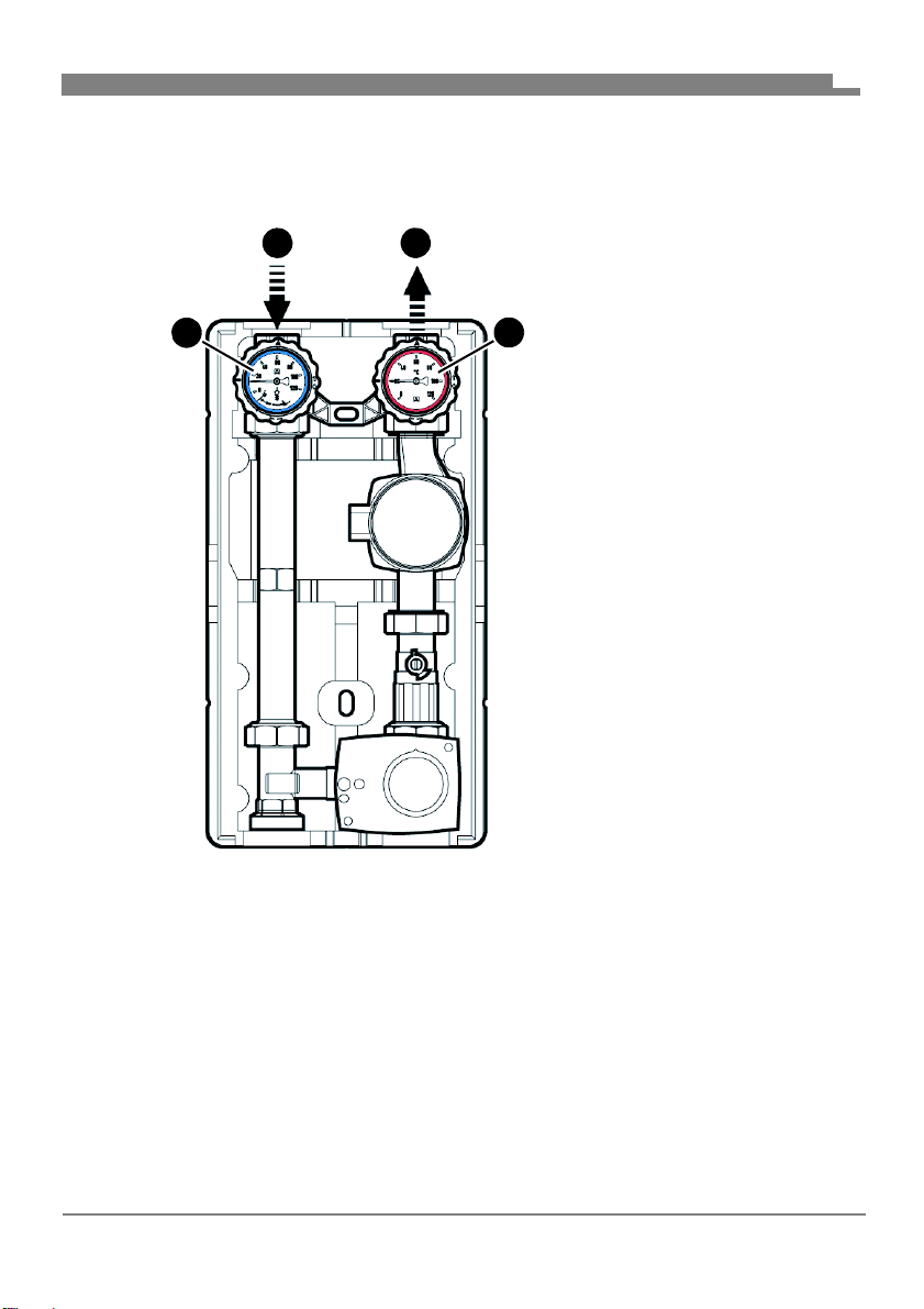
Montage
B
A
C
B
D
5.1.1 Permuter départ/retour
Sauf indication contraire, toutes les informations dans cette notice technique se rapportent au type d'installation "départ à droite."
FR
A. Retour
B. Départ
C. Vanne à sphère avec ther-
momètre rouge
D. Vanne à sphère avec ther-
momètre bleu
Figure 5: Départ à droite (état de livraison)
FA PG - 06/2019 - 008.15 442 99_02 - FR
14
Page 69
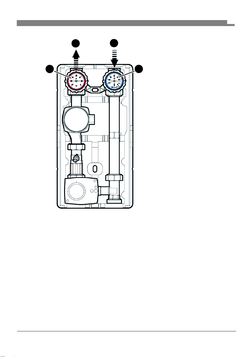
Montage
D
A
A
B
C
D
FR
A. Départ
B. Retour
C. Vanne à sphère avec ther-
momètre bleu
D. Vanne à sphère avec ther-
momètre rouge
Figure 6: Départ à gauche
FA PG - 06/2019 - 008.15 442 99_02 - FR
15
Page 70
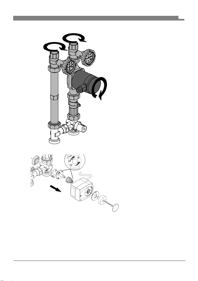
Montage
FR
1. Échangez les tuyauteries
gauche et droite.
2. Tournez la tête de la
pompe.
3. Permutez le servomoteur.
- Départ à droite
4. Démontez le servomoteur.
FA PG - 06/2019 - 008.15 442 99_02 - FR
16
Page 71
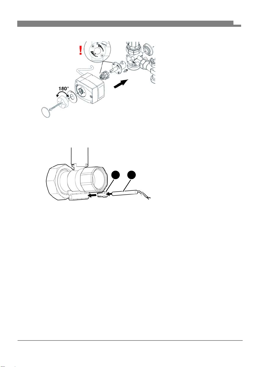
Montage
A B
5. Montez le servomoteur.
- Départ à gauche
6. Monter l'isolation supérieure.
5.1.2 Montage de sondes de température (en option)
Selon le type de sonde de
température (B), il peut être
nécessaire de raccourcir la
pièce (A).
FR
FA PG - 06/2019 - 008.15 442 99_02 - FR
17
Page 72

Montage
5.2 Montage du produit
5.2.1 Montage du produit sur un distributeur modulaire
AVIS
CHARGE MÉCANIQUE ET CONTRAINTE
• Assurez-vous que le produit n'est pas soumis à des charges mécaniques et
des contraintes lors du branchement du produit.
• Si nécessaire, installez un compensateur à tuyau ondulé pour compenser les
charges mécaniques et les contraintes.
La non-observation de ces instructions peut causer des dommages matériels.
1. Retirez l'isolation.
2. Vissez le groupe de pompe sur le distributeur modulaire.
3. Visser les tuyaux du circuit de chauffage aux raccordements supérieurs (sans contrainte mécanique).
4. Montez l'isolation complète.
5.2.2 Montage au mur
FR
AVIS
CHARGE MÉCANIQUE ET CONTRAINTE
• Lors du montage du produit au mur, assurez-vous que le produit n'est pas
soumis à des charges mécaniques et des contraintes.
La non-observation de ces instructions peut causer des dommages matériels.
FA PG - 06/2019 - 008.15 442 99_02 - FR
18
Page 73
Montage
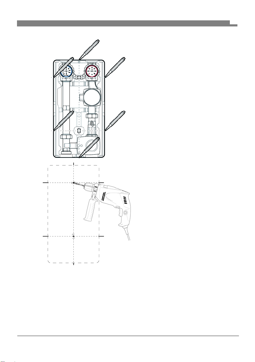
FR
1. Retirez l'isolation supérieure.
2. Placez le produit sur le mur et alignez-le avec une nivelle.
3. Marquez six points de repère.
4. Reliez entre eux les points de
repère opposés.
5. Percez des trous (Ø 10 mm) à la
position des points de repère du
milieu.
6. Introduisez les chevilles jointes.
7. Vissez le goujon long à double
filet dans le trou supérieur.
8. Vissez le goujon court à double
filet dans le trou inférieur.
9. Accrochez le produit avec l'isolation inférieure et fixez le produit avec une
rondelle et un écrou.
10.Raccordez et visser les conduites rigides du circuit de chauffage sur les
raccords de la robinetterie (sans contrainte mécanique).
11.Montez l'isolation supérieure.
FA PG - 06/2019 - 008.15 442 99_02 - FR
19
Page 74
Montage
5.3 Branchement électrique
DANGER
CHOC ÉLECTRIQUE
• Assurez-vous que le degré de protection contre les chocs électriques (classe
de protection, isolation double) ne soit pas réduit par le type de l'installation
électrique.
La non-observation de ces instructions entraîne la mort ou des blessures
graves.
DANGER
CHOC ÉLECTRIQUE PROVOQUÉ PAR LES PIÈCES SOUS TENSION
• Coupez la tension secteur avant d'effectuer les travaux et prenez toutes les
mesures nécessaires pour éviter la remise en marche.
• Assurez-vous que des objets conducteurs ou des fluides conducteurs ne
causent aucun risque.
La non-observation de ces instructions entraîne la mort ou des blessures
graves.
FR
1. Branchez la pompe de circulation et le servomoteur conformément aux
instructions du fabricant.
FA PG - 06/2019 - 008.15 442 99_02 - FR
20
Page 75
Mise en service
6 Mise en service
6.1 Mise en service
Assurez-vous que les vannes à sphères avec thermomètre sont en posi-
tion 0°.
1. Effectuez un test de pression.
2. Vérifiez l'étanchéité de tous les raccords à vis.
3. Mettez les vannes à sphère sur la position 45° pour remplir l'installation.
4. Remplissez l'installation et pressurisez l'installation.
5. Mettez les vannes à sphère sur la position 0°.
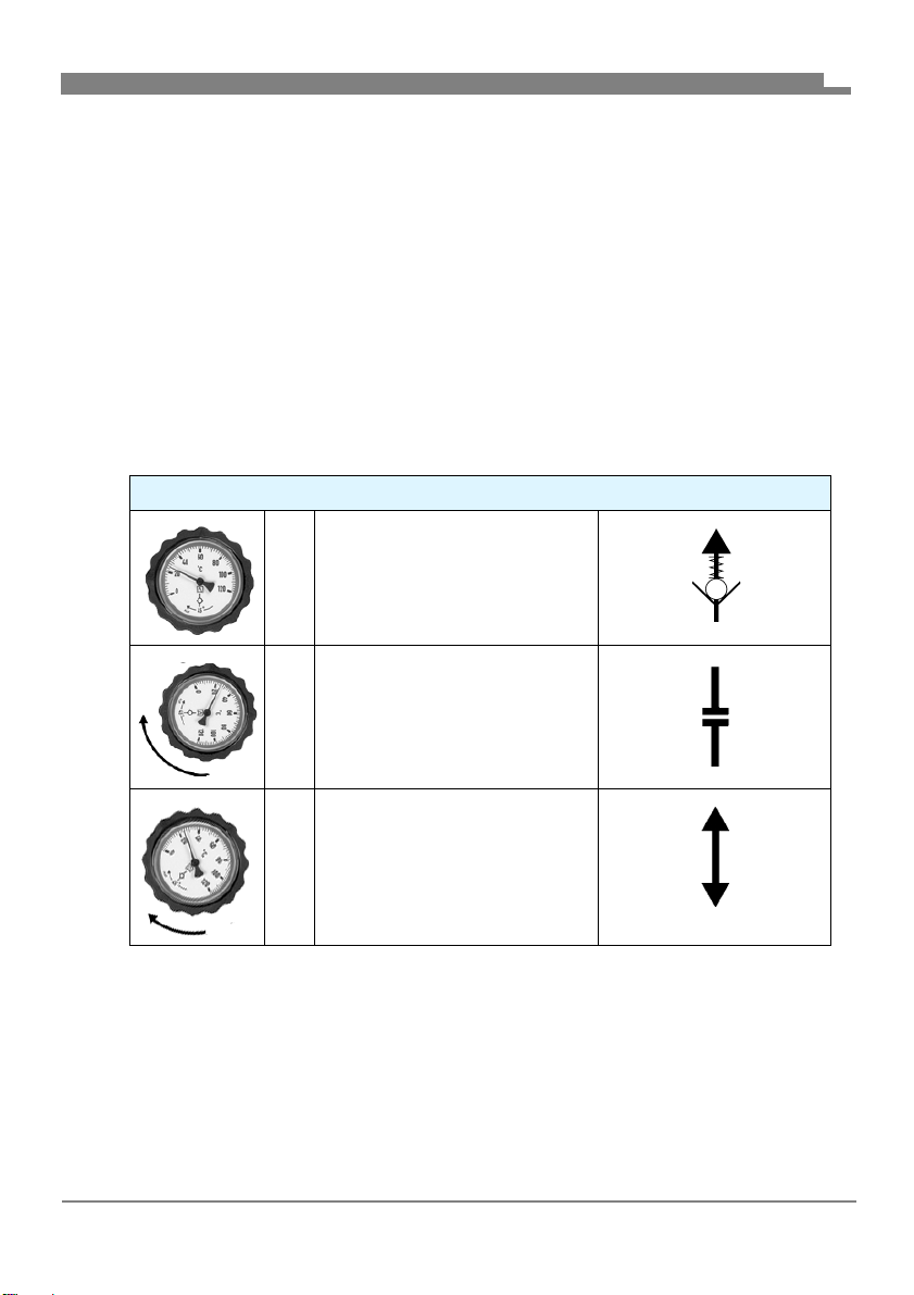
6.1.1 Vannes à sphère avec thermomètre
Vannes à sphère avec thermomètre
0° Fonctionnement normal :
Frein à commande par gravité activé
90 ° Entretien :
Vanne à sphère fermée
FR
45 ° Mise en service, remplis-
sage, purge d'air, rinçage :
Les deux côtés ouverts (le
frein à commande par gravité est désactivé)
7 Service
L'installation fonctionne `condition que les vannes à sphère avec thermomètre ainsi que les vannes à sphère soient ouvertes (position 0°, voir chapitre "Vannes à sphère avec thermomètre").
FA PG - 06/2019 - 008.15 442 99_02 - FR
21
Page 76
Maintenance
8 Maintenance
8.1 Intervalles de maintenance
Quand Opération
1 fois par mois Effectuez un contrôle visuel et vérifiez l'étanchéité
de l'installation.
Si nécessaire Remplacez la pompe de circulation.
8.2 Opérations de maintenance
DANGER
CHOC ÉLECTRIQUE PROVOQUÉ PAR LES PIÈCES SOUS TENSION
• Coupez la tension secteur avant d'effectuer les travaux et prenez toutes les
mesures nécessaires pour éviter la remise en marche.
La non-observation de ces instructions entraîne la mort ou des blessures
graves.
8.2.1 Remplacer la pompe de circulation défectueuse
1. Fermez la vanne à sphère avec thermomètre rouge et la vanne à
sphère de la tuyauterie de la pompe (position 90°).
2. Remplacez la pompe de circulation
(voir notice technique du fabricant).
3. Ouvrez à nouveau la vanne à sphère avec thermomètre et la vanne à
sphère (position 0°).
FR
FA PG - 06/2019 - 008.15 442 99_02 - FR
22
Page 77

Suppression des dérangements
9 Suppression des dérangements
Les dérangements ne figurant pas dans les mesures décrites dans ce chapitre doivent être éliminés uniquement par le fabricant.
Observez également les instructions correspondantes du fabricant en cas de
dérangements de la pompe de circulation ou du servomoteur.
Problème Cause possible Action corrective
Installation bruyante Présence d'air dans
l'installation
Pompe de circulation
mal réglée
Autre dérangement - Veuillez contacter
Purgez d'air l'installation
Vérifiez le réglage de la
pompe de circulation
l'AFRISO Service Hotline
FR
FA PG - 06/2019 - 008.15 442 99_02 - FR
23
Page 78

Mise hors service et élimination
10 Mise hors service et élimination
Pour éliminer le produit, conformez-vous aux règlements, normes et
consignes de sécurité en vigueur.
Les composants électroniques ne doivent pas être éliminés avec les ordures
ménagères.
1. Débranchez le produit de la tension d'alimentation.
2. Démontez le produit (voir chapitre "Montage", effectuez
les opérations en ordre inverse).
3. Éliminez le produit.
11 Retour
Avant de retourner le produit, il faut que vous preniez contact avec nous.
12 Garantie
Les informations sur la garantie figurent dans nos "Conditions générales
de vente" sur le site www.daikin.com ou dans votre contrat de vente.
FR
FA PG - 06/2019 - 008.15 442 99_02 - FR
24
Page 79

__________________________
__________________________
__________________________
__________________________
__________________________
__________________________
__________________________
__________________________
__________________________
__________________________
__________________________
__________________________
__________________________
__________________________
__________________________
__________________________
__________________________
__________________________
__________________________
__________________________
__________________________
__________________________
__________________________
__________________________
__________________________
__________________________
__________________________
__________________________
__________________________
__________________________
__________________________
__________________________
__________________________
__________________________
__________________________
__________________________
__________________________
__________________________
__________________________
__________________________
__________________________
__________________________
__________________________
__________________________
__________________________
__________________________
__________________________
__________________________
__________________________
__________________________
__________________________
__________________________
__________________________
__________________________
__________________________
__________________________
__________________________
__________________________
__________________________
__________________________
__________________________
__________________________
__________________________
__________________________
__________________________
__________________________
__________________________
__________________________
__________________________
__________________________
__________________________
Page 80

Page 81
156077 PGDK
156075 PGMK
Lezen voor gebruik!
Alle veiligheidsinstructies opvolgen!
Bewaren voor toekomstig gebruik!
Nederlands
Page 82

Over deze gebruiksaanwijzing
1 Over deze gebruiksaanwijzing
In deze gebruiksaanwijzing wordt de pompgroep met en zonder menger
beschreven (hieronder ook “product” genoemd).
Deze gebruiksaanwijzing is onderdeel van het product.
• U mag het product pas gebruiken als u de gebruiksaanwijzing helemaal
hebt gelezen en de inhoud ervan hebt begrepen.
• Zorg ervoor dat de gebruiksaanwijzing voor alle werkzaamheden aan en
met het product te allen tijde beschikbaar is.
• Geef de gebruiksaanwijzing en alle bij het product horende documenten
aan alle gebruikers van het product door.
• Als u van mening bent dat de gebruiksaanwijzing, fouten, tegenstrijdigheden of onduidelijkheden bevat, neem dan vóór het gebruik ervan contact
op met de fabrikant.
Deze gebruiksaanwijzing is door de auteurswet beschermd en mag uitsluitend binnen het wettelijk toegestane kader worden gebruikt. Wijzigingen
voorbehouden.
Voor schade en gevolgschade die door niet-naleving van deze gebruiksaanwijzing evenals het niet naleven van de op de plaats van het product geldende voorschriften, bepalingen en normen ontstaat, kan de fabrikant op
geen enkele wijze aansprakelijk worden gesteld resp. zal er geen enkele
vorm van garantie worden verleend.
NL
FA PG - 06/2019 - 008.15 442 99_02 - NL
2
Page 83
Informatie betreffende de veiligheid
2 Informatie betreffende de veiligheid
2.1 Waarschuwingen en gevarenklassen
In deze gebruiksaanwijzing vindt u waarschuwingen die op potentiële gevaren en risico's wijzen. Aanvullend aan de aanwijzingen in deze gebruiksaanwijzing dient u alle op locatie geldende bepalingen, normen en veiligheidsvoorschriften in acht te nemen. Zorg er vóór het gebruik van het product voor
dat u alle bepalingen, normen en veiligheidsvoorschriften kent en dat deze
worden nageleefd.
Waarschuwingen worden in deze gebruiksaanwijzing met symbolen en signaalwoorden aangeduid. Afhankelijk van de ernst van een gevaarlijke situatie
worden waarschuwingen in verschillende gevarenklassen opgedeeld.
GEVAAR
GEVAAR duidt op een direct gevaarlijke situatie die bij niet-naleving onvermijdelijk tot een zwaar of dodelijk ongeval leidt.
WAARSCHUWING
WAARSCHUWING duidt op een mogelijke gevaarlijke situatie die bij nietnaleving tot een zwaar of dodelijk ongeval of materiële schade kan leiden.
NL
AANWIJZING
AANWIJZING duidt op een mogelijk gevaarlijke situatie die bij niet-naleving
tot materiële schade kan leiden.
Daarnaast worden in deze gebruiksaanwijzing de volgende symbolen
gebruikt:
Dit is het algemene waarschuwingssymbool. Het duidt op
het gevaar voor letsels en
verband met dit symbool beschreven aanwijzingen in acht
om ongevallen met dodelijke afloop, letsels en materiële
schade te voorkomen.
materiële schade. Neem alle in
FA PG - 06/2019 - 008.15 442 99_02 - NL
3
Page 84
Informatie betreffende de veiligheid
Dit symbool waarschuwt voor gevaarlijke elektrische spanning. Als dit symbool in een waarschuwing te zien is, is er
sprake van gevaar voor een elektrische schok.
2.2 Reglementair gebruik
Dit product is uitsluitend geschikt voor het laten circuleren van de volgende
media in intrinsiek veilige, gesloten thermische verwarmingsinstallaties:
• verwarmingswater conform VDI 2035
• water-glycol-mengsels met maximaal 20% bijmenging
Een ander gebruik is niet conform de voorschriften en veroorzaakt risico's.
Controleer vóór het gebruik van het product of het product geschikt is voor
de door u voorziene toepassing. Houd hierbij in ieder geval rekening met het
volgende:
• alle op locatie geldende bepalingen, normen en veiligheidsvoorschriften
• alle voor het product gespecificeerde bepalingen en gegevens
• de bepalingen van de door u voorziene toepassing
Voer daarenboven een risicobeoordeling uit met betrekking tot de concrete,
door u voorziene toepassing volgens een erkende procedure en tref in overeenstemming met het resultaat alle vereiste veiligheidsmaatregelen. Houd
hierbij ook rekening met de mogelijke gevolgen van de inbouw of integratie
van het product in een systeem of installatie.
Voer bij het gebruik van het product alle werkzaamheden uitsluitend uit onder
de in de gebruiksaanwijzing en op het typeplaatje gespecificeerde voorwaarden en binnen de gespecificeerde gegevens en in overeenstemming met alle
op locatie geldende bepalingen, normen en veiligheidsvoorschriften.
NL
FA PG - 06/2019 - 008.15 442 99_02 - NL
4
Page 85

Informatie betreffende de veiligheid
2.3 Te verwachten verkeerd gebruik
Het product mag in het bijzonder in de volgende gevallen en voor de volgende doelen niet worden toegepast:
• gebruik met drinkwater
• gebruik met kleverige, bijtende of licht ontvlambare media
• gebruik in installaties met temperaturen boven 110 °C
(bijv. zonne-installaties)
2.4 Kwalificatie van het personeel
Werkzaamheden aan en met dit product mogen uitsluitend door geschoolde
krachten worden uitgevoerd die de inhoud van deze gebruiksaanwijzing en
alle bij het product horende documenten kennen en begrijpen.
De geschoolde krachten moeten op grond van hun vakkundige opleiding,
kennis en ervaringen in staat zijn om mogelijke gevaren te voorzien en te herkennen die door de toepassing van het product kunnen ontstaan.
De geschoolde krachten moeten op de hoogte zijn van alle geldende bepalingen, normen en veiligheidsvoorschriften die bij werkzaamheden aan en
met het product in acht moeten worden genomen.
2.5 Persoonlijke beschermende uitrusting
Gebruik altijd de vereiste persoonlijke beschermende uitrusting. Houd er bij
werkzaamheden aan en met het product ook rekening mee dat op locatie
gevaren kunnen voorkomen die niet direct van het product uitgaan.
NL
2.6 Wijzigingen aan het product
Voer uitsluitend werkzaamheden aan en met het product uit die in deze
gebruiksaanwijzing staan beschreven. Breng geen wijzigingen aan die in
deze gebruiksaanwijzing niet beschreven staan.
FA PG - 06/2019 - 008.15 442 99_02 - NL
5
Page 86

Transport en opslag
3 Transport en opslag
Het product kan door verkeerd transport en onjuiste opslag worden beschadigd.
AANWIJZING
BESCHADIGING VAN HET PRODUCT
• Zorg ervoor dat tijdens het transport en de opslag van het product de gespecificeerde omgevingscondities worden nageleefd.
• Gebruik voor het transport de originele verpakking.
• Sla het product alleen op in een droge en schone omgeving.
• Zorg ervoor dat het transport en de opslag van het product schokvrij plaatsvindt.
Niet-naleving van deze aanwijzingen kan tot materiële schade leiden.
NL
FA PG - 06/2019 - 008.15 442 99_02 - NL
6
Page 87

Productbeschrijving
4 Productbeschrijving
Het product is een voorgemonteerde, op lekdichtheid gecontroleerde en
warmte-geïsoleerde pompgroep.
De universele isolatie maakt de inbouw mogelijk van nagenoeg elke standaard in de handel verkrijgbare circulatiepomp (met aansluiting G1
bouwlengte van 180 mm) zonder veel nabewerking.
Door de tweede kogelafsluiter in de terugstroomleiding kan de pomp worden
vervangen zonder dat de installatie moet worden leeggemaakt.
Door het modulaire systeem kan bovendien de voorloop naar keuze links of
rechts worden aangebracht. Optioneel kunnen in alle kogelafsluiters temperatuursensoren Ø 6 mm worden gemonteerd.
1
/
en een
2
NL
FA PG - 06/2019 - 008.15 442 99_02 - NL
7
Page 88
4.1 Overzicht
1
2
B
C
D
E
F
A
Productbeschrijving
1. Terugloop
2. Voorloop
A. Kogelafsluiter, afsluitbaar,
B. Kogelafsluiter, afsluitbaar,
C. Circulatiepomp (verschil-
D. Kogelafsluiter
E. 3-weg-menger met servo-
F. Isolatie
NL
met thermometer blauw
en zwaartekrachtrem
met thermometer rood
lende fabrikanten)
motor
Afbeelding 1: PrimoTherm® componenten
FA PG - 06/2019 - 008.15 442 99_02 - NL
8
Page 89
Productbeschrijving
4.2 Uitvoeringen
De variabele isolatie kan worden gebruikt om de voorloop links of rechts aan
te brengen.
Afbeelding 2: Voorloop rechts (afbeelding links)
Afbeelding 3: Voorloop links (afbeelding midden)
Afbeelding 4: Zonder servomotor (afbeelding rechts)
NL
FA PG - 06/2019 - 008.15 442 99_02 - NL
9
Page 90
Productbeschrijving
ca. 250 mm
ca. 175 mm
ca. 475 mm
ca. 152 mm
4.3 Afmetingen en aansluitingen
NL
FA PG - 06/2019 - 008.15 442 99_02 - NL
10
Page 91
Productbeschrijving
B
1
B
B
A
ca. 125 mm
ca. 60 mm
A. G1
B. G1½
NL
4.4 Vergunningsdocumenten, attesten, verklaringen
Bij uitvoering met circulatiepomp, zie handleiding van de fabrikant van de
pomp.
FA PG - 06/2019 - 008.15 442 99_02 - NL
11
Page 92
Productbeschrijving
4.5 Technische gegevens
Parameter Waarde
Algemene gegevens
Afmetingen met isolatie
(B x H x D)
Gewicht Ca. 5,5 kg met menger
Materiaal appendages Messing
Materiaal isolatie Polypropyleen EPP
Installatiedruk Max. 10 bar
Asafstand 125 mm
Systeemaansluitingen Ketel R1
Kvs-waarde 4,8 m
Temperatuurbereik
Medium Max. 110 °C
Drukverlies
Voorloopleiding Kvs = 6,9 m
Terugstroomleiding Kvs = 6,7 m
Totaal Kvs = 4,8 m
250 x 475 x 152 mm
Ca. 7,2 kg zonder menger
(neem de maximale druk van de
gebruikte circulatie pomp in acht)
1
/
2
Verwarmingskring Rp1
3
/h
3
/h
3
/h
3
/h
NL
FA PG - 06/2019 - 008.15 442 99_02 - NL
12
Page 93

Montage
5 Montage
WAARSCHUWING
BRANDWONDEN DOOR HETE VLOEISTOF
Water in verwarmingsinstallaties staat onder een hoge druk en kan temperaturen tot meer dan 100 °C bereiken.
• Vergewis u ervan dat het verwarmingswater is afgekoeld voordat u de installatie opent en het product monteert.
Niet-naleving van deze aanwijzing kan tot de dood, zware letsels of materiële schade leiden.
5.1 Montage voorbereiden
Zorg ervoor dat het product zo wordt gemonteerd dat in de ingebouwde
toestand geen externe krachten op de appendages inwerken.
Zorg ervoor dat het product door las- en soldeerwerkzaamheden aan de
installatie niet wordt oververhit.
- Bouw het product pas in na deze werkzaamheden.
Zorg ervoor dat de nominale druk van het product aan de geplande
waarde van de installatie voldoet.
Zorg ervoor dat de vloeistof in de installatie verenigbaar is met het toepas-
singsgebied van het product.
Zorg ervoor dat de leiding van het product vóór de montage goed is door-
gespoeld.
- Verontreinigingen zoals laskorrels, hennep of metalen spaanders
maken het product ondicht.
NL
FA PG - 06/2019 - 008.15 442 99_02 - NL
13
Page 94
Montage
B
A
C
B
D
5.1.1 Voorloop/terugloop wisselen
Indien niet anders vermeld hebben alle gegevens in deze gebruiksaanwijzing betrekking op de inbouwwijze “voorloop rechts”.
NL
A. Terugloop
B. Voorloop
C. Rode thermometer-afslui-
ter
D. Blauwe thermometer-
afsluiter
Afbeelding 5: Voorloop rechts (oorspronkelijke toestand)
FA PG - 06/2019 - 008.15 442 99_02 - NL
14
Page 95
Montage
D
A
A
B
C
D
NL
A. Voorloop
B. Terugloop
C. Blauwe thermometer-
afsluiter
D. Rode thermometer-afslui-
ter
Afbeelding 6: Voorloop links
FA PG - 06/2019 - 008.15 442 99_02 - NL
15
Page 96
Montage
NL
1. Wissel de linker en de
rechter leiding.
2. Draai de pompkop.
3. Wissel de servomotor.
- Voorloop rechts
4. Bouw de servomotor uit.
FA PG - 06/2019 - 008.15 442 99_02 - NL
16
Page 97

Montage
A B
5. Bouw de servomotor in.
- Voorloop links
6. Breng de bovenste isolatie aan.
5.1.2 Temperatuursensor monteren (optioneel)
Al naargelang het type temperatuursensor (B) kan het
nodig zijn dat de klemhuls (A)
moet worden ingekort.
NL
FA PG - 06/2019 - 008.15 442 99_02 - NL
17
Page 98

Montage
5.2 Product monteren
5.2.1 Product op moduleverdeler monteren
AANWIJZING
MECHANISCHE BELASTING EN SPANNINGEN
• Vergewis u bij het aansluiten van het product ervan dat het product niet wordt
blootgesteld aan mechanische belastingen en spanningen.
• Bouw, indien nodig, een ribbelbuiscompensator in om mechanische belastingen en spanningen te compenseren.
Niet-naleving van deze aanwijzingen kan tot materiële schade leiden.
1. Verwijder de isolatie.
2. Schroef de pompgroep op de moduleverdeler.
3. Schroef de buisleidingen van de verwarmingskringloop spanningsvrij
vast aan de bovenste aansluitingen.
4. Breng de complete isolatie aan.
5.2.2 Wandmontage
NL
AANWIJZING
MECHANISCHE BELASTING EN SPANNINGEN
• Vergewis u bij het monteren van het product aan de wand ervan dat het product niet wordt blootgesteld aan mechanische belastingen en spanningen.
Niet-naleving van deze aanwijzingen kan tot materiële schade leiden.
FA PG - 06/2019 - 008.15 442 99_02 - NL
18
Page 99
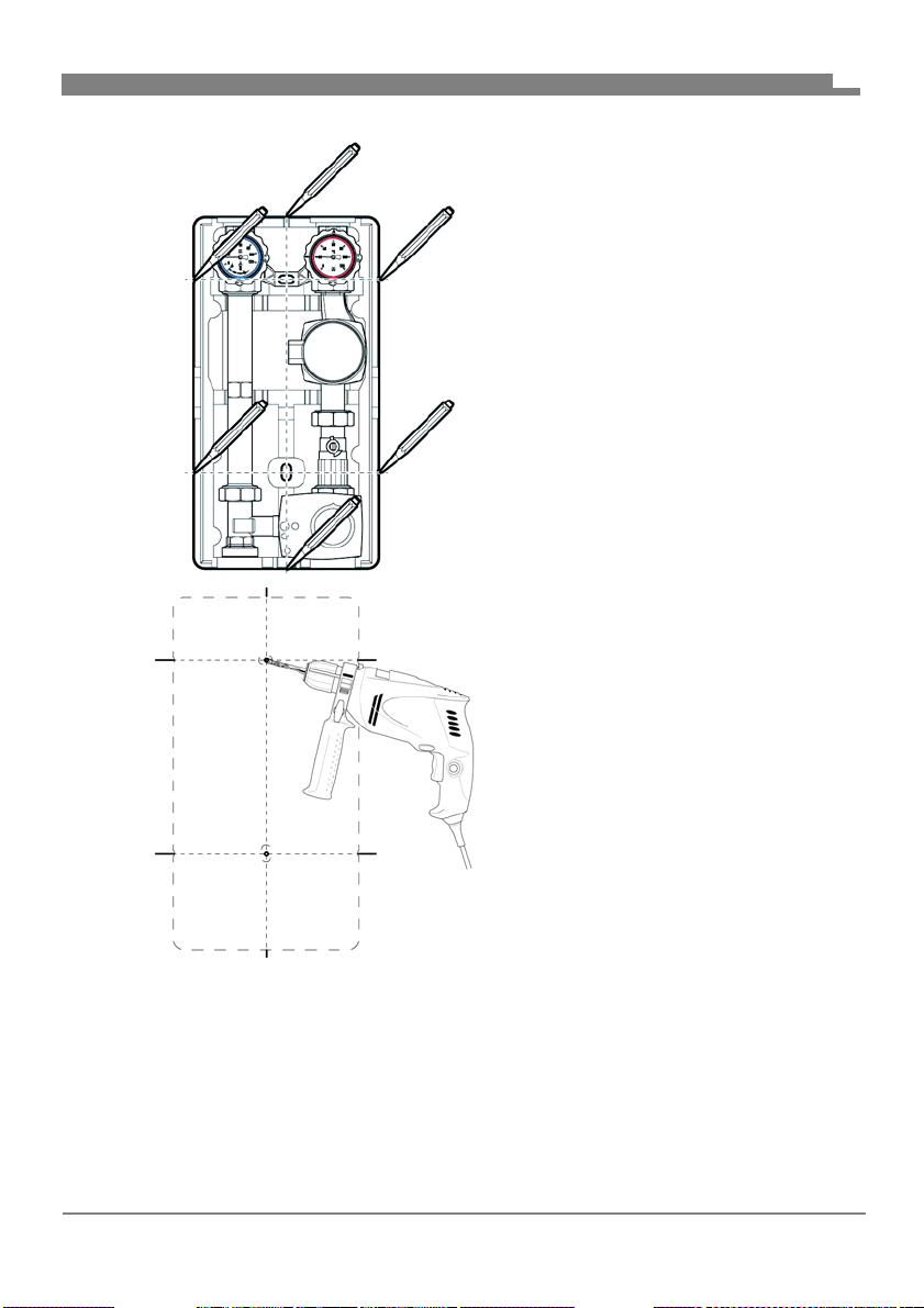
Montage
NL
1. Verwijder de bovenste isolatie.
2. Houd het product tegen de wand
en breng in de juiste stand met
een waterpas.
3. Maak op zes punten markeringen.
4. Verbind de tegenover elkaar liggende punten met elkaar.
5. Boor steeds bij de middelste markeringen een gat.
(Ø 10 mm).
6. Breng de bijgevoegde pluggen
aan.
7. Draai boven de lange stokschroef
in.
8. Draai beneden de korte stokschroef in.
9. Hang het product met de onderste isolatie in en zet het product vast met
onderlegplaatje en moer.
10.Verbind de buisleidingen van de verwarmingskring met de aansluitingen
van de appendages en schroef ze spanningsvrij vast.
11.Breng de bovenste isolatie aan.
FA PG - 06/2019 - 008.15 442 99_02 - NL
19
Page 100
Montage
5.3 Elektrische aansluiting
GEVAAR
ELEKTRISCHE SCHOK
• Zorg ervoor dat door het soort elektrische installatie de bescherming tegen
elektrische schok (beschermingsklasse, beschermende isolatie) niet wordt
verminderd.
Niet-naleving van deze aanwijzingen leidt tot de dood of zware letsels.
GEVAAR
ELEKTRISCHE SCHOK DOOR ONDER SPANNING STAANDE DELEN
• Onderbreek vóór het begin van de werkzaamheden de netspanning en
beveilig deze tegen herinschakelen.
• Zorg ervoor dat van elektrisch geleidende voorwerpen of media geen gevaren kunnen uitgaan.
Niet-naleving van deze aanwijzingen leidt tot de dood of zware letsels.
1. Sluit de circulatiepomp en de servomotor aan volgens de betreffende
handleiding van de fabrikant.
NL
FA PG - 06/2019 - 008.15 442 99_02 - NL
20
 Loading...