

Page 1
EDUS 39 - 600 - F7_a
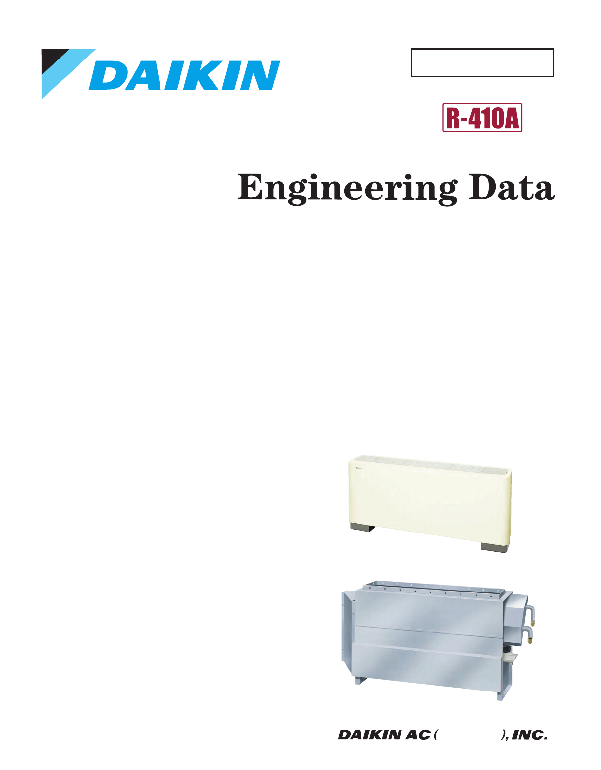
FXLQ-M / FXNQ-M
Floor Standing Type /
Concealed Floor Standing Type
AMERICAS
Page 2

EDUS39-600-F7_a
FXLQ-M / FXNQ-M
Floor Standing Type /
Concealed Floor Standing Type
1. Features.................................................................................................. 2
2. Specifications ........................................................................................ 3
2.1 FXLQ ....................................................................................................... 3
2.2 FXNQ ...................................................................................................... 4
3. Dimensions ........................................................................................... 5
3.1 FXLQ ...................................................................................................... 5
3.2 FXNQ ..................................................................................................... 7
4. Piping Diagrams..................................................................................... 9
5. Wiring Diagrams ....................................................................................10
6. Electric Characteristics ..........................................................................11
7. Capacity Tables ....................................................................................12
7.1 Cooling Capacity ....................................................................................12
7.2 Heating Capacity ....................................................................................13
8. Sound Levels ........................................................................................14
9. Installation............................................................................................. 15
10.Accessories ........................................................................................... 27
FXLQ-M/FXNQ-M 1
Page 3
Features EDUS39-600-F7_a
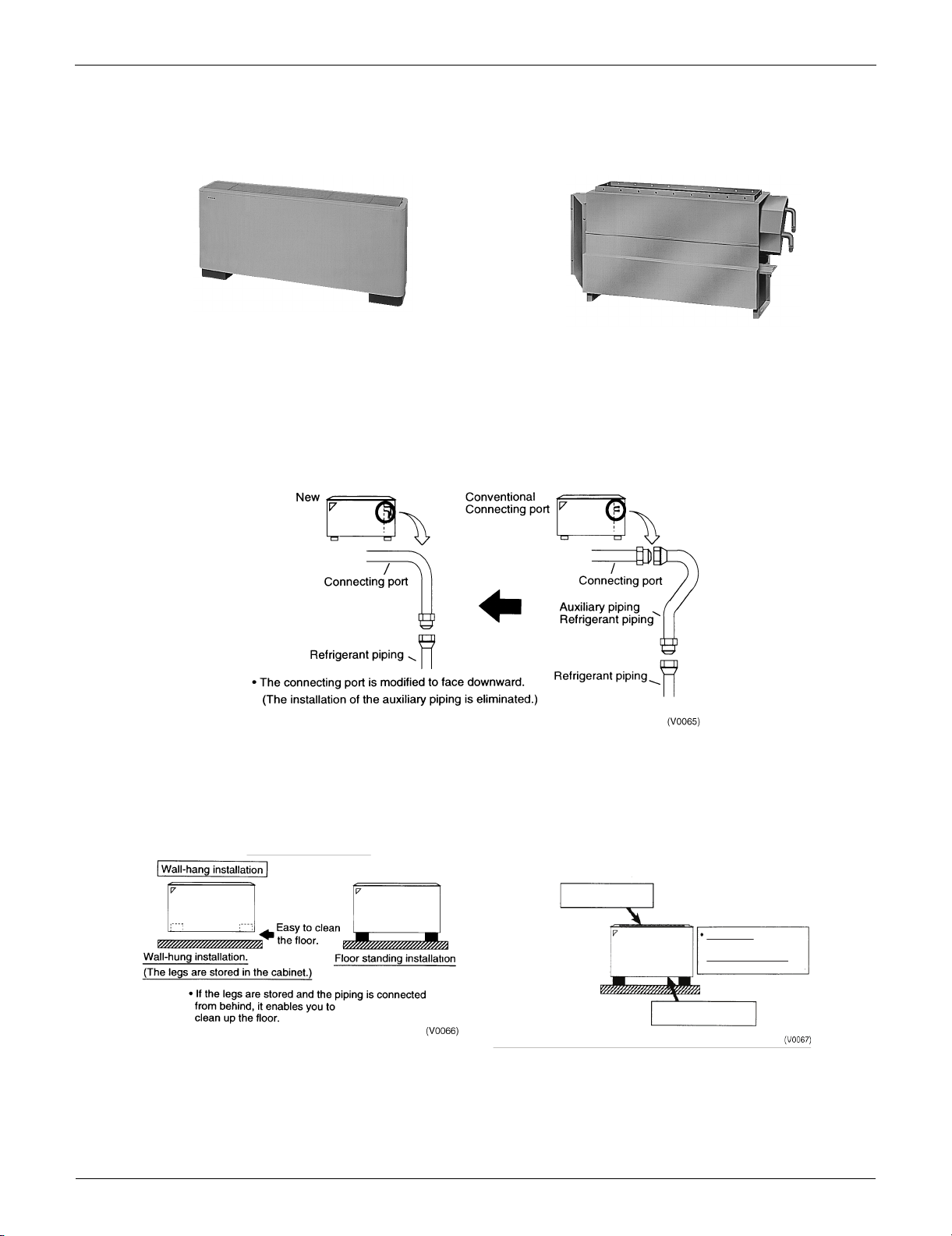
Long life filter is provided
as standard accessory.
New Model:
Clean every 6 months.
Conventional Model:
Clean every 2 weeks.
Easy-to-clean
plastic grill.
Grill is easy to clean.
1. Features
Efficient for perimeter zone airconditioning.
FXLQ-M
1. New roundshape is attractive in an office environment.
Inconspicuous discharge grille and bottom frame color.
Slim top plate for streamlined elegance.
2. Improvement ease of installation
The piping connection work is easy to access.
Can be built into counter
FXNQ-M
2 FXLQ-M / FXNQ-M
3. Easy maintenance
Wall units allow more space plus access to floor for cleaning. (Exposed type)
Easier maintenance of discharge grille.
The interval of filter cleaning is prolonged.
EASY MAINTENANCE
Page 4
EDUS39-600-F7_a Specifications
2. Specifications
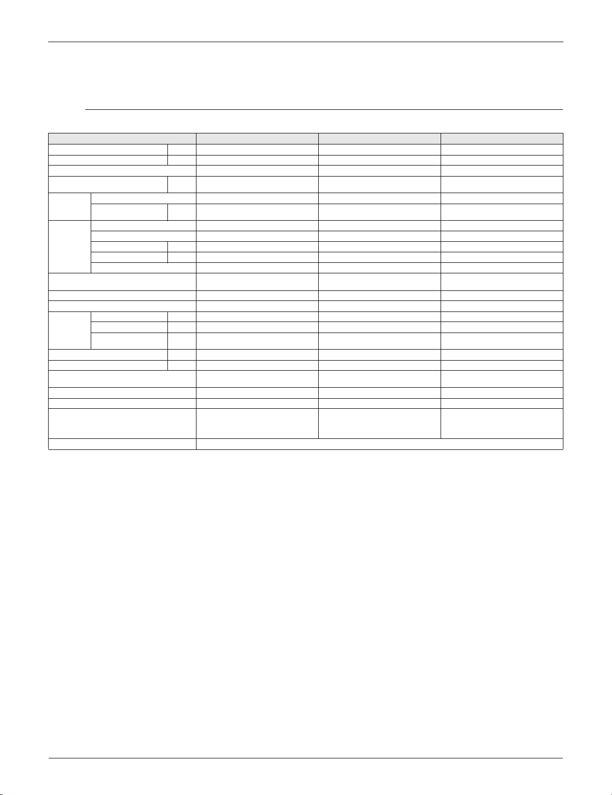
2.1 FXLQ
Floor Standing Type
Model FXLQ12MVJU FXLQ18MVJU FXLQ24MVJU
Cooling Capacity
Heating Capacity
Casing Color Ivory White (5Y7.5/1) Ivory White (5Y7.5/1) Ivory White (5Y7.5/1)
Dimensions: (H×W×D)
Coil (Cross
Fin Coil)
Fan
Temperature Control
Sound Absorbing Thermal Insulation Material Glass Fiber/ Urethane Foam Glass Fiber/ Urethane Foam Glass Fiber/ Urethane Foam
Air Filter Resin Net (with Mold Resistant) Resin Net (with Mold Resistant) Resin Net (with Mold Resistant)
Piping
Connections
Machine Weight (Mass) Lbs 66 80 80
Sound Level (H/L)
Safety Devices
Refrigerant Control Electronic Expansion Valve Electronic Expansion Valve Electronic Expansion Valve
Connectable Outdoor Unit R-410A Series R-410A Series R-410A Series
Standard Accessories
Drawing No. C:3D045640
Notes:
1. Nominal cooling capacities are based on the following conditions:
Return air temperature: 80°FDB, 67°FWB
Outdoor temperature: 95°FDB
Equivalent ref. piping length: 25 ft / 7.5 m (Horizontal)
2. Nominal heating capacities are based on the following conditions:
Return air temperature: 70°FDB.
Outdoor temperature: 47°FDB, 43°FWB
Equivalent ref. piping length: 25 ft / 7.5 m (Horizontal)
3. Capacities are net, including a deduction for cooling (an addition for heating) for indoor fan motor heat.
4. Anechoic chamber conversion value, measured under JISB8616 conditions. During actual operation,
these values are normally somewhat higher as a result of installation conditions.
5. Refer to page 11 for Power Input.
1
2
Rows × Stages × FPI 3 ×14 × 17 3 ×14 ×1 7 3 ×1 4× 17
Face Area
Model 2D14B13 2D14B20 2D14B20
Type Sirocco Fan Sirocco Fan Sirocco Fan
Motor Output kW 0.025 0.035 0.035
Air Flow Rate (H/L) cfm 280/210 490/380 560/420
Drive Direct Drive Direct Drive Direct Drive
Liquid Pipes in / mm φ1/4 / 6.4 mm (Flare Connection) φ1/4 / 6.4 mm (Flare Connection) φ3/8 / 9.5 mm (Flare Connection)
Gas Pipes in / mm φ1/2 / 12.7 mm (Flare Connection) φ1/2 / 12.7 mm (Flare Connection) φ5/8 / 15.8 mm (Flare Connection)
Drain Pipe in (mm)
4
Btu/h 12,000 18,000 24,000
Btu/h 13,500 20,000 27,000
in
(mm)
ft²
(mm²)
dBA364041
23–5/8 × 44–7/8 × 8–3/4”
(600 x 1139.8 x 222.3 mm)
2.15 ft. (655.3 mm) 3.04 ft. (926.6 mm) 3.04 ft. (926.6 mm)
Microprocessor Thermostat for
Cooling and Heating
φ27/32” (21 mm) O.D
(Vinyl Chloride)
Thermal Protector for Fan Motor
Operation Manual, Installation
Manual, Insulation for Fitting, Drain
Hose, Clamps, Screws, Washers, Level
Adjustment Screw.
Fuse,
23–5/8 × 55–7/8 × 8–3/4”
(600 x 1419.2 x 222.3 mm)
Microprocessor Thermostat for Cooling
Operation Manual, Installation Manual,
Insulation for Fitting, Drain Hose,
Clamps, Screws, Washers, Level
Adjustment Screw.
and Heating
φ27/32” (21 mm) O.D
(Vinyl Chloride)
Thermal Protector for Fan Motor
Fuse,
23–5/8 × 55–7/8 × 8–3/4”
(600 x 1419.2 x 222.3 mm)
Microprocessor Thermostat for Cooling
Operation Manual, Installation Manual,
Insulation for Fitting, Drain Hose,
Clamps, Screws, Washers, Level
Adjustment Screw.
and Heating
φ27/32” (21 mm) O.D
(Vinyl Chloride)
Thermal Protector for Fan Motor
Fuse,
FXLQ-M / FXNQ-M 3
Page 5
Specifications EDUS39-600-F7_a
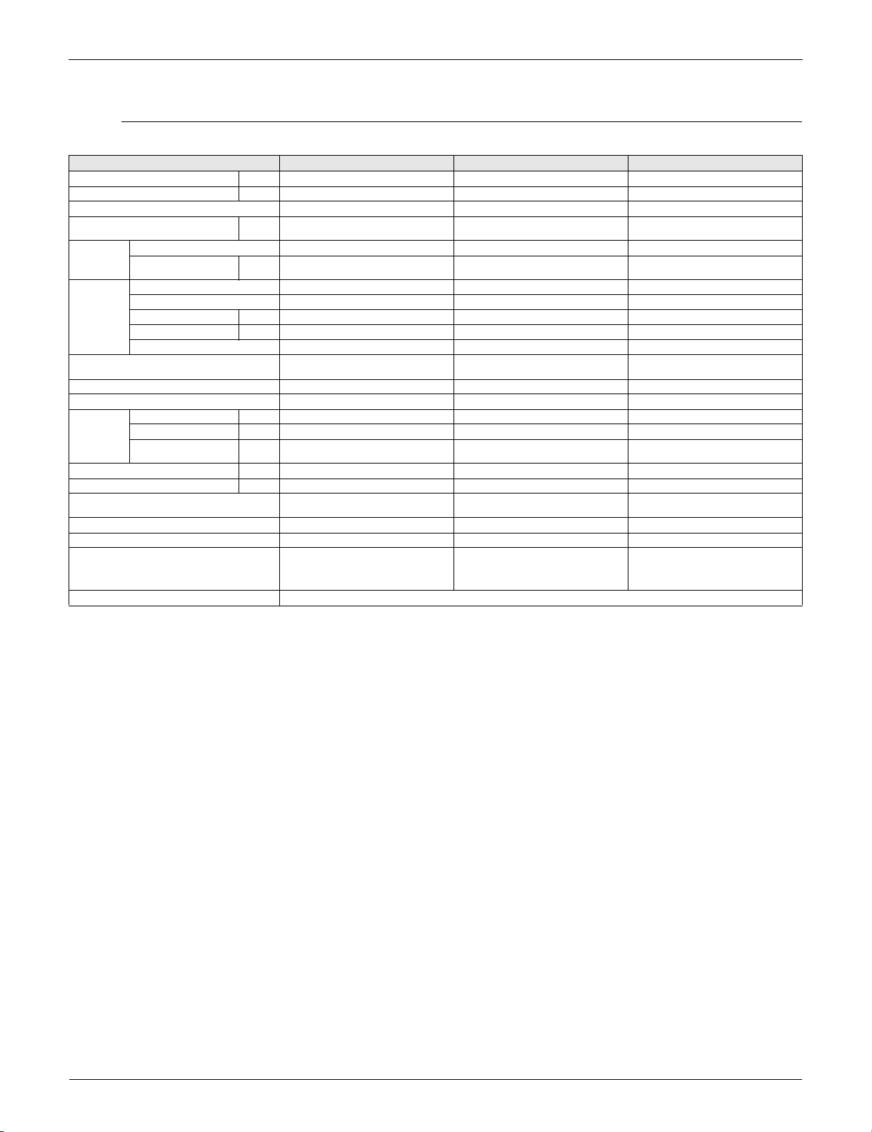
2.2 FXNQ
Concealed Floor Standing Type
Model FXNQ12MVJU FXNQ18MVJU FXNQ24MVJU
Cooling Capacity
Heating Capacity
Casing Color Galvanized Steel Plate Galvanized Steel Plate Galvanized Steel Plate
Dimensions: (H×W×D) in (mm)
Coil (Cross
Fin Coil)
Fan
Temperature Control
Sound Absorbing Thermal Insulation Material Glass Fiber/ Urethane Foam Glass Fiber/ Urethane Foam Glass Fiber/ Urethane Foam
Air Filter Resin Net (with Mold Resistant) Resin Net (with Mold Resistant) Resin Net (with Mold Resistant)
Piping
Connections
Machine Weight (Mass) Lbs 51 60 60
Sound Level (H/L)
Safety Devices
Refrigerant Control Electronic Expansion Valve Electronic Expansion Valve Electronic Expansion Valve
Connectable Outdoor Unit R-410A Series R-410A Series R-410A Series
Standard Accessories
Drawing No. 3D045640
Notes:
1. Nominal cooling capacities are based on the following conditions:
Return air temperature: 80°FDB, 67°FWB
Outdoor temperature: 95°FDB
Equivalent ref. piping length: 25 ft / 7.5 m (Horizontal)
2. Nominal heating capacities are based on the following conditions:
Return air temperature: 70°FDB.
Outdoor temperature: 47°FDB, 43°FWB
Equivalent ref. piping length: 25 ft / 7.5 m (Horizontal)
3. Capacities are net, including a deduction for cooling (an addition for heating) for indoor fan motor heat.
4. Anechoic chamber conversion value, measured under JISB8616 conditions. During actual operation,
these values are normally somewhat higher as a result of installation conditions.
5. Refer to page 11 for Power Input.
1
2
Rows × Stages × FPI 3 ×14 ×17 3 × 14 × 17 3 × 14 × 17
Face Area
Model 2D14B13 2D14B20 2D14B20
Type Sirocco Fan Sirocco Fan Sirocco Fan
Motor Output kW 0.025 0.035 0.035
Air Flow Rate (H/L) cfm 280/210 490/380 560/420
Drive Direct Drive Direct Drive Direct Drive
Liquid Pipes in / mm φ1/4 / 6.4 mm (Flare Connection) φ1/4 / 6.4 mm (Flare Connection) φ3/8 / 9.5 mm (Flare Connection)
Gas Pipes in / mm φ1/2 / 12.7 mm (Flare Connection) φ1/2 / 12.7 mm (Flare Connection) φ5/8 / 15.8 mm (Flare Connection)
Drain Pipe in / mm
4
Btu/h 12,000 18,000 24,000
Btu/h 13,500 20,000 27,000
24 × 42–1/8 × 8–5/8”
(609.6 x 1070 x 219mm)
ft²
(mm²)
dBA364041
Operation Manual, Installation
Manual, Insulation for Fitting, Drain
Hose, Clamps, Screws, Washers, Level
Adjustment Screw.
2.15 ft. (655.3 mm) 3.04 ft. (926.6 mm) 3.04 ft. (926.6 mm)
Microprocessor Thermostat for
Cooling and Heating
φ27/32 (685.8 / 812.8 mm) O.D
(Vinyl Chloride)
Thermal Protector for Fan Motor
Fuse,
Operation Manual, Installation Manual,
Insulation for Fitting, Drain Hose,
Clamps, Screws, Washers, Level
Adjustment Screw.
24×53–1/8×8–5/8”
(609.6 x 1349.4 x 219mm)
Microprocessor Thermostat for Cooling
and Heating
φ27/32 (685.8 / 812.8 mm) O.D
(Vinyl Chloride)
Thermal Protector for Fan Motor
Fuse,
24×53–1/8×8–5/8”
(609.6 x 1349.4 x 219mm)
Microprocessor Thermostat for Cooling
Operation Manual, Installation Manual,
Insulation for Fitting, Drain Hose,
Clamps, Screws, Washers, Level
Adjustment Screw.
and Heating
φ27/32 (685.8 / 812.8 mm) O.D
(Vinyl Chloride)
Thermal Protector for Fan Motor
Fuse,
4 FXLQ-M / FXNQ-M
Page 6
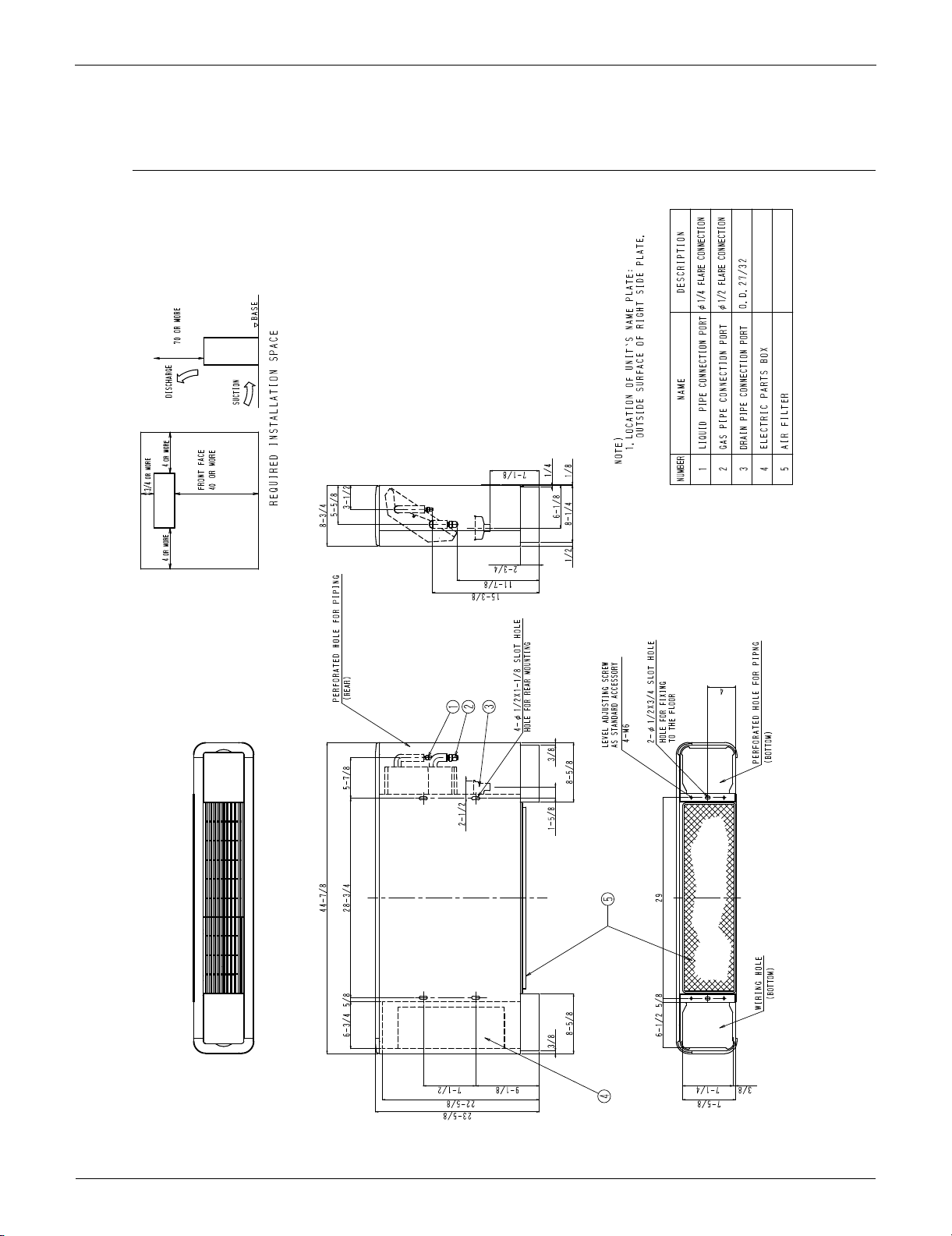
EDUS39-600-F7_a Dimensions
3D045642
3. Dimensions
3.1 FXLQ
FXLQ12MVJU
FXLQ-M / FXNQ-M 5
Page 7
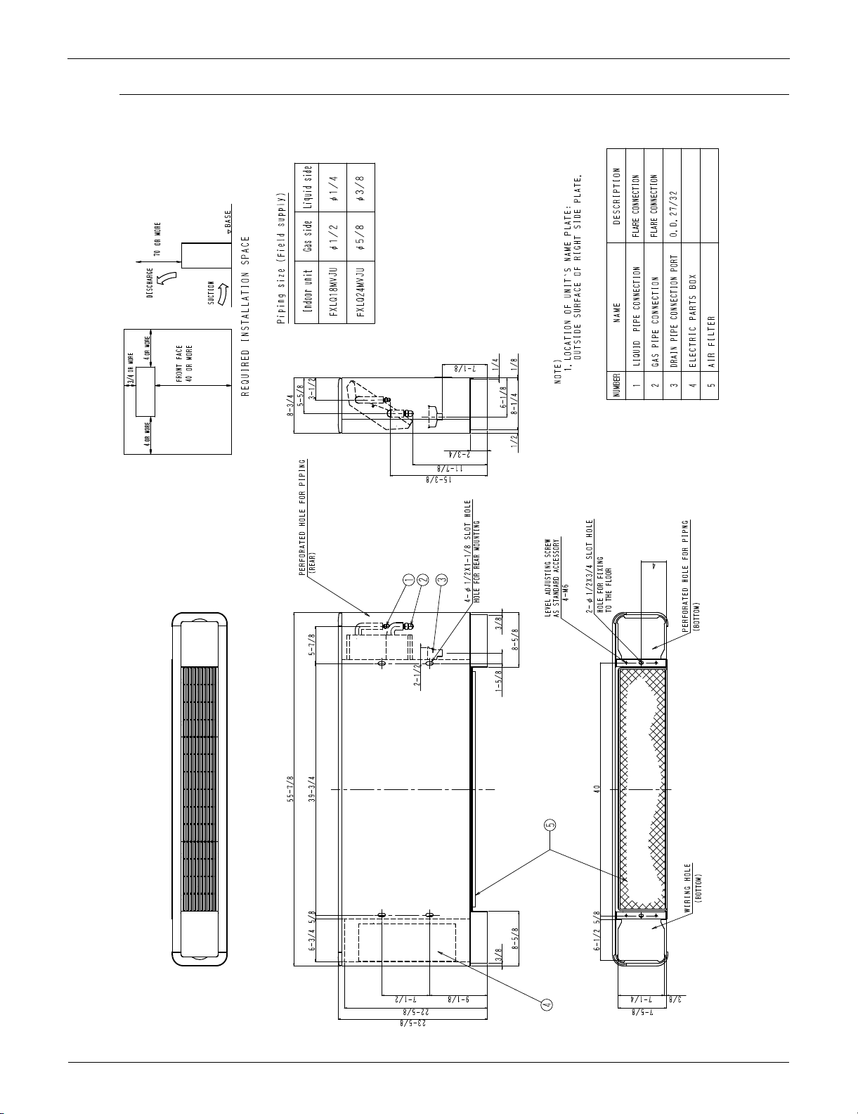
Dimensions EDUS39-600-F7_a
3D045643
FXLQ18MVJU
FXLQ24MVJU
6 FXLQ-M / FXNQ-M
Page 8
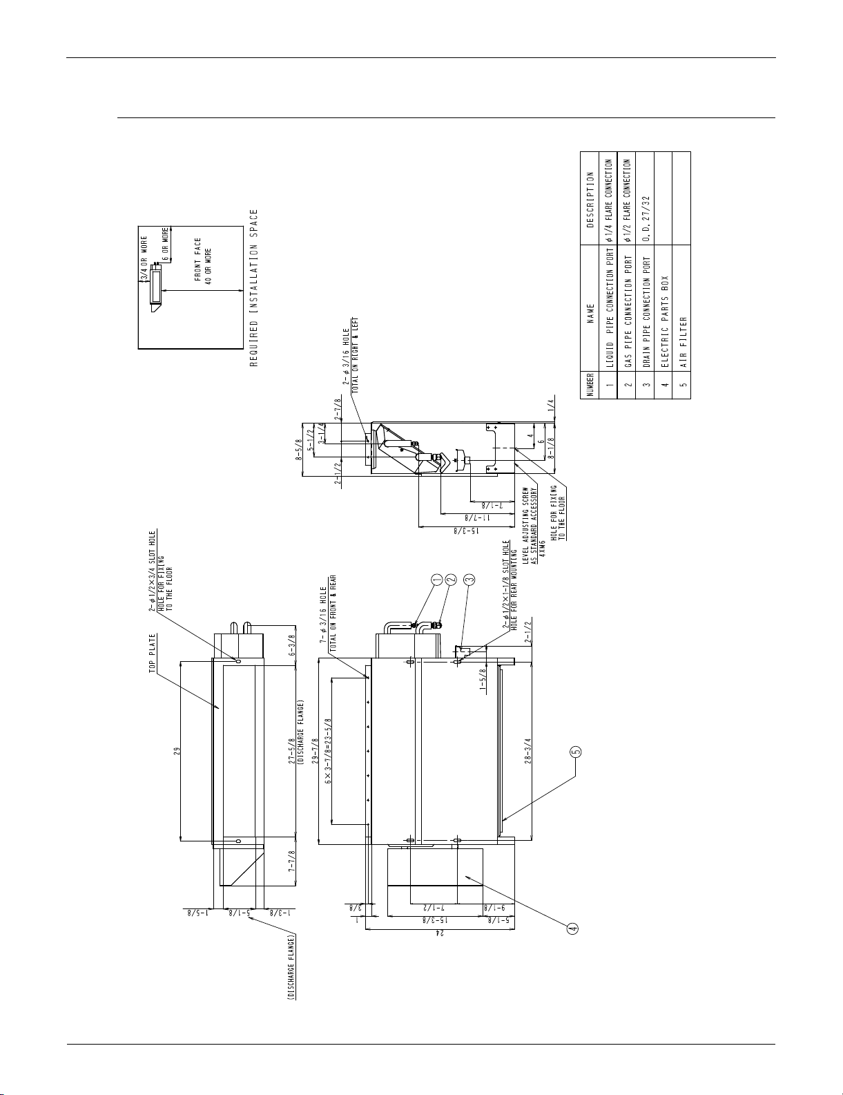
EDUS39-600-F7_a Dimensions
3D045650
3.2 FXNQ
FXNQ12MVJU
FXLQ-M / FXNQ-M 7
Page 9
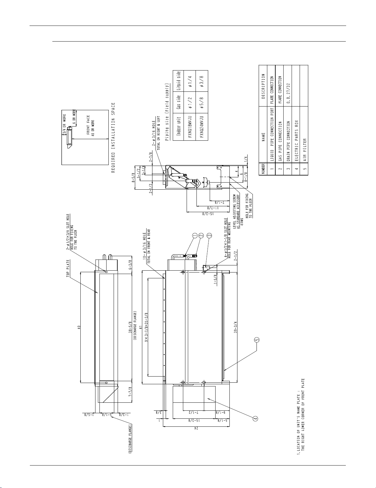
Dimensions EDUS39-600-F7_a
3D045651
FXNQ18MVJU
FXNQ24MVJU
8 FXLQ-M / FXNQ-M
Page 10
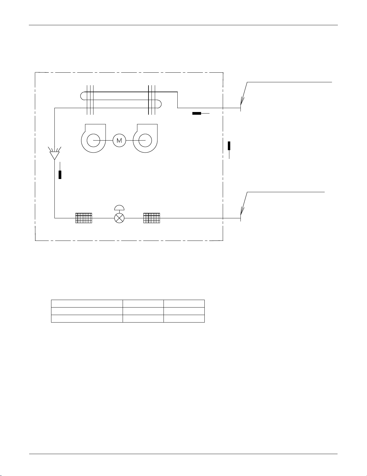
EDUS39-600-F7_a Piping Diagrams
C:4D034245C
Heat exchanger
Gas piping connection port
Liquid piping connection port
Fan
R3T
R1T
Electronic
expansion valve
Filter Filter
R2T
4. Piping Diagrams
R1T : Thermistor for suction air temperature
R2T : Thermistor for liquid line temperature
R3T : Thermistor for gas line temperature
Capacity GAS Liquid
12/18M φ1/2 φ1/4
24M φ5/8 φ3/8
FXLQ-M / FXNQ-M 9
Page 11
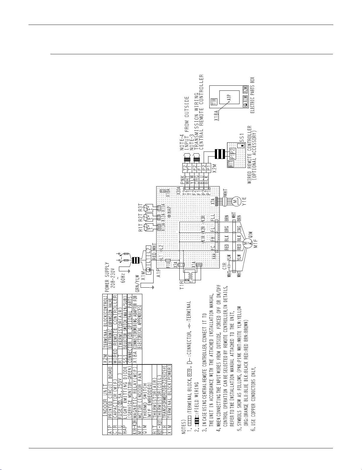
Wiring Diagrams EDUS39-600-F7_a
3D045644A
5. Wiring Diagrams
FXLQ12M/18M/24MVJU
FXNQ12M/18M/24MVJU
10 FXLQ-M / FXNQ-M
Page 12
EDUS39-600-F7_a Electric Characteristics
4D047090
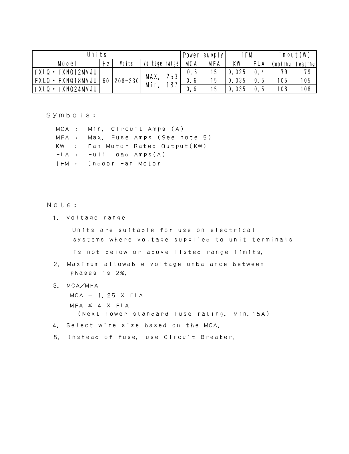
6. Electric Characteristics
FXLQ-M / FXNQ-M 11
Page 13
Capacity Tables EDUS39-600-F7_a
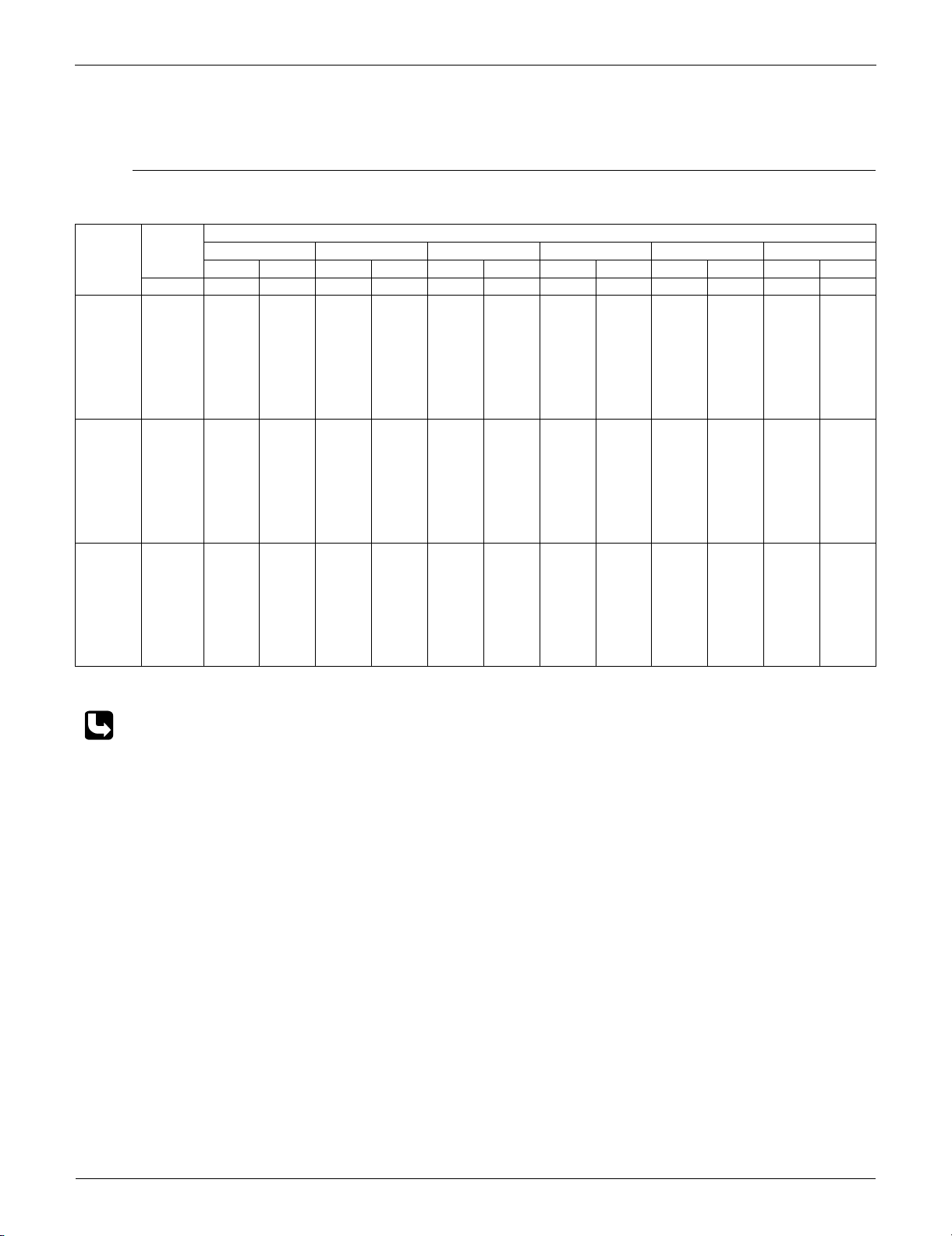
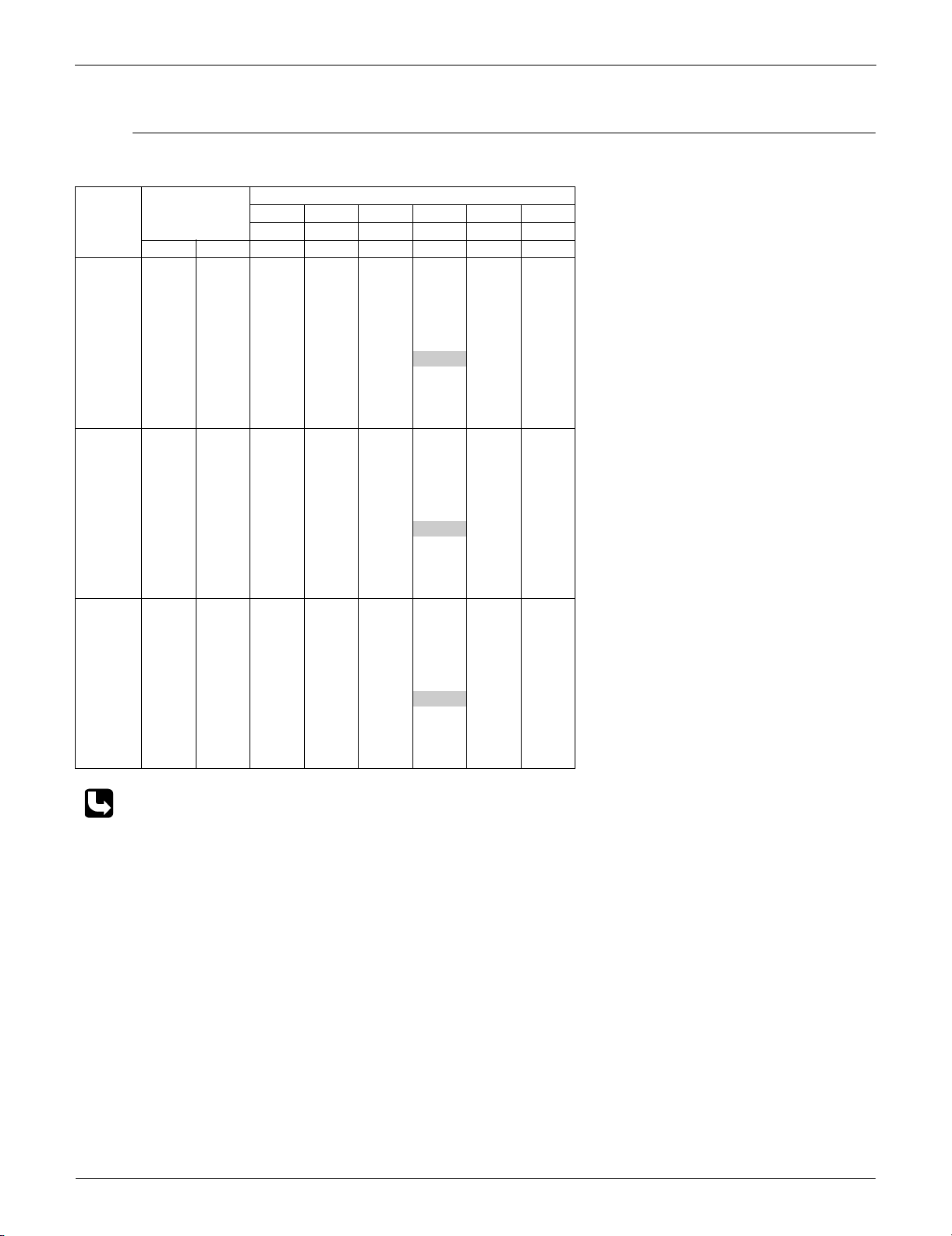
7. Capacity Tables
7.1 Cooling Capacity
FXLQ-M / FXNQ-M
Cooling capacity
Outdoor
Unit size
12
18
24
TC : Total capacity ; kW
SHC : Sensible heat capacity ; kW
air temp.
°FDB MBh MBh MBh MBh MBh MBh MBh MBh MBh MBh MBh MBh
TC SHC TC SHC TC SHC TC SHC TC SHC TC SHC
75 9.5 7.5 10.7 7.9 12.0 8.3 13.3 8.4 14.0 8.4 14.3 7.9
79 9.5 7.5 10.7 7.9 12.0 8.3 13.3 8.4 13.8 8.4 14.0 7.8
83 9.5 7.5 10.7 7.9 12.0 8.3 13.3 8.4 13.6 8.3 13.8 7.7
87 9.5 7.5 10.7 7.9 12.0 8.3 13.2 8.4 13.3 8.1 13.6 7.7
91 9.5 7.5 10.7 7.9 12.0 8.3 13.0 8.4 13.1 8.1 13.4 7.6
95 9.5 7.5 10.7 7.9 12.0 8.3 12.7 8.4 12.9 8.0 13.1 7.6
99 9.5 7.5 10.7 7.9 12.0 8.3 12.5 8.4 12.7 7.9 12.9 7.6
103 9.5 7.5 10.7 7.9 12.0 8.3 12.3 8.3 12.4 7.8 12.7 7.6
75 14.2 10.7 16.1 11.5 18.0 12.2 19.9 12.7 21.0 12.8 21.4 12.2
79 14.2 10.7 16.1 11.5 18.0 12.2 19.9 12.7 20.7 12.7 21.1 12.0
83 14.2 10.7 16.1 11.5 18.0 12.2 19.9 12.7 20.4 12.6 20.7 11.9
87 14.2 10.7 16.1 11.5 18.0 12.2 19.8 12.7 20.0 12.4 20.4 11.7
91 14.2 10.7 16.1 11.5 18.0 12.2 19.4 12.6 19.7 12.3 20.1 11.6
95 14.2 10.7 16.1 11.5 18.0 12.2 19.1 12.6 19.3 12.1 19.7 11.4
99 14.2 10.7 16.1 11.5 18.0 12.2 18.8 12.6 19.0 12.0 19.4 11.2
103 14.2 10.7 16.1 11.5 18.0 12.2 18.4 12.4 18.7 11.9 19.0 11.0
75 18.9 14.1 21.5 15.1 24.0 15.9 26.5 16.6 28.0 16.6 28.5 16.0
79 18.9 14.1 21.5 15.1 24.0 15.9 26.5 16.6 27.6 16.6 28.1 15.7
83 18.9 14.1 21.5 15.1 24.0 15.9 26.5 16.6 27.1 16.4 27.6 15.5
87 18.9 14.1 21.5 15.1 24.0 15.9 26.4 16.6 26.7 16.2 27.2 15.2
91 18.9 14.1 21.5 15.1 24.0 15.9 25.9 16.6 26.2 16.0 26.7 15.0
95 18.9 14.1 21.5 15.1 24.0 15.9 25.5 16.5 25.8 15.8 26.3 14.7
99 18.9 14.1 21.5 15.1 24.0 15.9 25.0 16.5 25.3 15.6 25.8 14.5
103 18.9 14.1 21.5 15.1 24.0 15.9 24.6 16.3 24.9 15.4 25.4 14.2
61 64 67 70 72 75
Indoor Air Temp. °FWB
Refer to Outdoor Unit Capacity Tables : for the actual performance data of each indoor and outdoor unit combination.
12 FXLQ-M / FXNQ-M
Page 14
EDUS39-600-F7_a Capacity Tables
7.2 Heating Capacity
FXLQ-M / FXNQ-M
Heating Capacity
Indoor Air Temp. °FDB
Indoor unit
12
18
24
Outdoor Air Temp.
°FDB °FWB MBh MBh MBh MBh MBh MBh
22.0 20.0 11.7 11.7 11.6 11.6 11.6 11.6
26.0 24.0 12.2 12.2 12.2 12.2 12.2 12.1
30.0 28.0 12.8 12.8 12.7 12.7 12.7 12.3
35.0 32.0 13.3 13.3 13.3 13.3 13.0 12.3
39.0 36.0 13.9 13.9 13.9 13.5 13.0 12.3
44.0 40.0 14.5 14.4 14.0 13.5 13.0 12.3
47.0 43.0 14.9 14.7 14.0
51.0 47.0 15.4 14.7 14.0 13.5 13.0 12.3
54.0 50.0 15.5 14.7 14.0 13.5 13.0 12.3
57.0 53.0 15.5 14.7 14.0 13.5 13.0 12.3
60.0 56.0 15.5 14.7 14.0 13.5 13.0 12.3
22.0 20.0 17.5 17.5 17.4 17.4 17.4 17.4
26.0 24.0 18.3 18.3 18.3 18.3 18.2 18.2
30.0 28.0 19.2 19.1 19.1 19.1 19.1 18.4
35.0 32.0 20.0 20.0 19.9 19.9 19.5 18.4
39.0 36.0 20.8 20.8 20.8 20.0 19.5 18.4
44.0 40.0 21.7 21.6 21.0 20.0 19.5 18.4
47.0 43.0 22.3 22.1 21.0
51.0 47.0 23.1 22.1 21.0 20.0 19.5 18.4
54.0 50.0 23.2 22.1 21.0 20.0 19.5 18.4
57.0 53.0 23.2 22.1 21.0 20.0 19.5 18.4
60.0 56.0 23.2 22.1 21.0 20.0 19.5 18.4
22.0 20.0 23.3 23.3 23.3 23.2 23.2 23.2
26.0 24.0 24.5 24.4 24.4 24.3 24.3 24.3
30.0 28.0 25.6 25.5 25.5 25.5 25.4 24.5
35.0 32.0 26.7 26.6 26.6 26.6 26.0 24.5
39.0 36.0 27.8 27.7 27.7 27.0 26.0 24.5
44.0 40.0 28.9 28.9 28.0 27.0 26.0 24.5
47.0 43.0 29.7 29.5 28.0
51.0 47.0 30.8 29.5 28.0 27.0 26.0 24.5
54.0 50.0 31.0 29.5 28.0 27.0 26.0 24.5
57.0 53.0 31.0 29.5 28.0 27.0 26.0 24.5
60.0 56.0 31.0 29.5 28.0 27.0 26.0 24.5
62 65 68 70 72 75
TC TC TC TC TC TC
13.5 13.0 12.3
20.0 19.5 18.4
27.0 26.0 24.5
Refer to Outdoor Unit Capacity Tables : for the actual performance data of each indoor and outdoor unit combination.
FXLQ-M / FXNQ-M 13
Page 15
Sound Levels EDUS39-600-F7_a
4D052501
4D052502
4D052503
4D052504
4D052505
4D052506
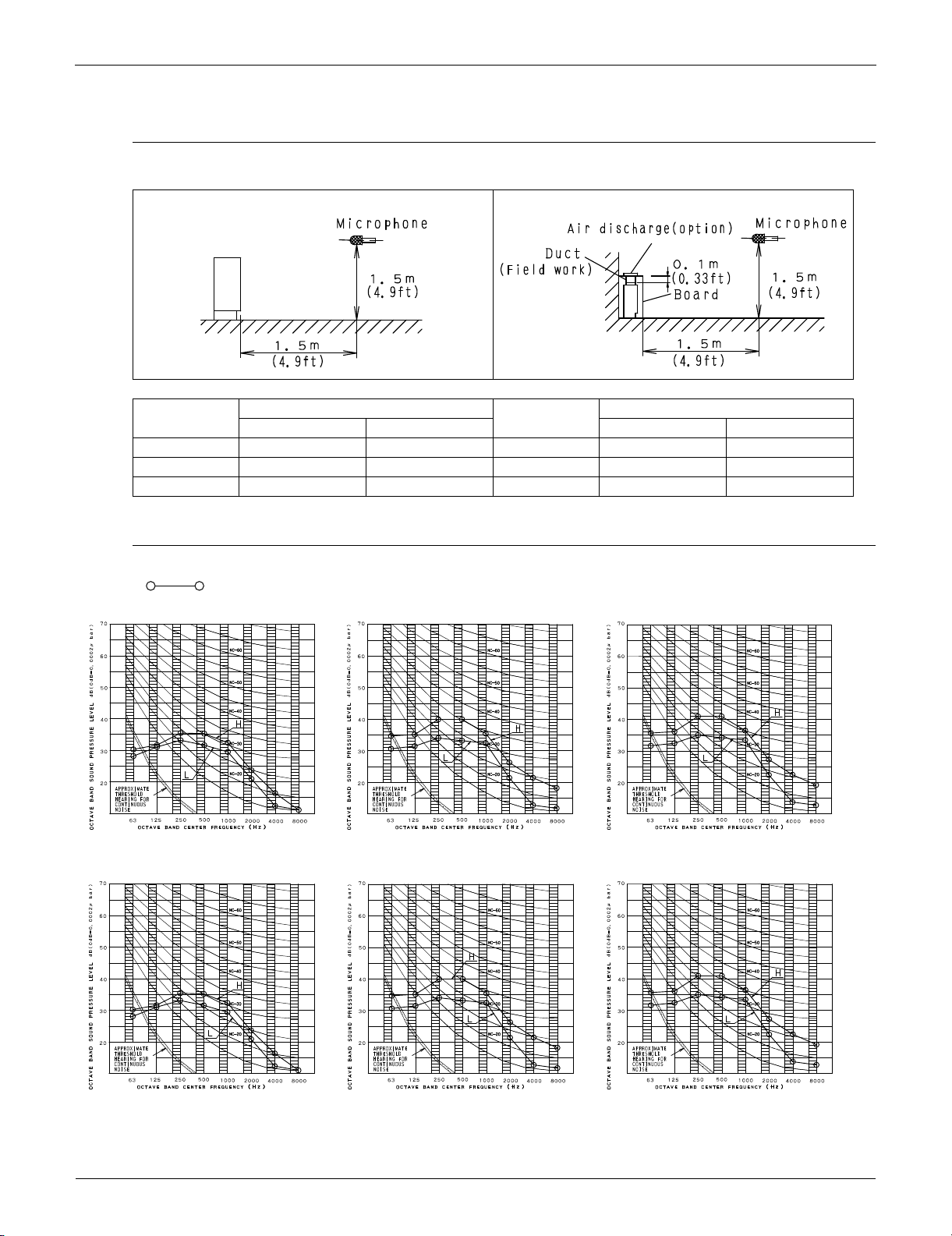
8. Sound Levels
Overall
Floor Standing Type Concealed Floor Standing Type
dBA
Model 208~230V, 60Hz Model 208~230V, 60Hz
HL HL
FXLQ12MVJU 36 33 FXNQ12MVJU 36 33
FXLQ18MVJU 40 35 FXNQ18MVJU 40 35
FXLQ24MVJU 41 36 FXNQ24MVJU 41 36
Note: Operation noise differs with operation and ambient conditions.
Octave Band Level
208V~230V
FXLQ12MVJU FXLQ18MVJU FXLQ24MVJU
FXNQ12MVJU FXNQ18MVJU FXNQ24MVJU
14 FXLQ-M / FXNQ-M
Page 16
EDUS39-600-F7_a Installation
FXLQ12MVJU
MODEL
4D045645
FXLQ18 24MVJU
22–1/2
28
FXNQ12MVJU
4D045652
FXNQ18 24MVJU
18–1/4
19–7/8
MODEL
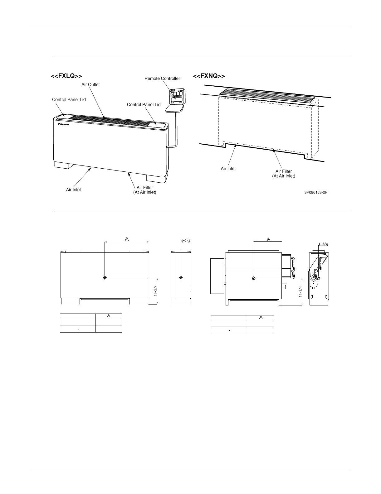
9. Installation
Installation Example
Center of Gravity
FXLQ FXNQ
FXLQ-M / FXNQ-M 15
Page 17
Installation EDUS39-600-F7
WARNING
1. SAFETY CONSIDERATIONS
Read these “SAFETY CONSIDERATIONS” carefully before
installing air conditioning equipment, and be sure to install it
correctly. After completing the installation, make sure that the
unit operates properly during the start-up operation.
Instruct the customer how to operate and maintain the unit.
Inform customers that they should store this Installation Man-
ual with the Operation Manual for future reference.
Always use a licensed installer or contractor to install this
product. Improper installation can result in water or refrigerant
leakage, electrical shock, fire, or explosion.
Meanings of DANGER, WARNING, CAUTION, and NOTE
symbols:
DANGER .............. Indicates an imminently hazardous
situation which, if not avoided,
results in death or serious injury.
WARNING ............ Indicates a potentially hazardous sit-
uation which, if not avoided, could
result in death or serious injury.
CAUTION ............. Indicates a potentially hazardous sit-
uation which, if not avoided, may
result in minor or moderate injury. It
may also be used to alert against
unsafe practices
NOTE .................... Indicates situations that may result
in equipment or propertydamage
accidents only.
• Do not ground units to water pipes or telephone
wires because incomplete grounding could cause a
severe shock hazard resulting in severe injury or
death. Do not ground ss to lightning rods because
lightning strikes can cause a severe shock hazard
resulting in severe injury or death. Do not install unit
in an area where flammable materials are present
due to risk of explosion resulting in serious injury or
death.
• Do not ground units to gas pipes because a gas leak
can result in an explosion causing serious injury or
death.
• Refrigerant gas is heavier than air and displaces oxygen. A massive leak can lead to oxygen depletion,
especially in basements, and an asphyxiation hazard
could occur leading to serious injury or death.
• If the refrigerant gas leaks during installation, ventilate the area immediately.
Refrigerant gas may produce toxic gas if it comes in contact
with fire such as from a fan, heater, stove, or cooking
device. Exposure to this gas could result in severe injury or
death.
• After completing the installation work, check that the
refrigerant gas does not leak.
Refrigerant gas can produce toxic gas if it comes in contact
with fire such as from a fan, heater, stove, or cooking
device. Exposure to this gas can cause in severe injury or
death.
• Children playing with plastic bags face the danger of
death by suffocation. Tear apart and throw away
plastic packaging so that children will not play with
them.
• Safely dispose of the packing materials. Packing
materials, such as nails and other metal or wooden parts,
may cause stabs or other injuries.
• Ask your dealer or an authorized personnel to carry out
installation work. Do not try to install the unit by yourself.
Improper installation may result in water leakage, electric
shocks, or fire.
• Perform installation work in accordance with this
installation manual.
Improper installation may result in water leakage, electric
shocks, or fire.
• Be sure to use only the specified accessories and
parts for installation work.
Failure to use the specified parts may result in water leakage, electric shocks, fire, or the unit falling.
• Install the air conditioner on a foundation strong
enough to withstand the weight of the unit.
A foundation of insufficient strength may result in the equipment falling and causing injuries.
• Carry out the specified installation work after taking
account of strong winds, typhoons, or earthquakes.
Improper installation work may result in the equipment falling and causing accidents.
• Make sure that a separate power supply circuit is
provided for this unit and that all electrical work is
carried out by an authorized personnel according to
local laws, regulations, and this installation manual.
An insufficient power supply capacity or improper electrical
construction may lead to electric shocks, or fire.
• Make sure that all wiring is secured, the specified
wires are used, and no external forces act on the terminal connections or wires.
Improper connections or installation may result in fire.
• When wiring the power supply and connecting the
remote controller wiring and transmission wiring,
position the wires so that the electric parts box lid
can be securely fastened.
Improper positioning of the electric parts box lid may result
in electric shocks, fire, or the terminals overheating.
• Before touching electrical parts, turn off the unit.
• Do not touch the switch with wet fingers.
Touching a switch with wet fingers can cause electric
shock.
• Be sure to install an earth leakage breaker.
Failure to install a ground leakage breaker may result in
electric shocks, or fire.
• Do not install the air conditioner where the following
conditions exist:
(a) Mineral oil mist or an oil spray or vapor is produced, for
example in a kitchen.
Plastic parts may deteriorate and fall off or water may
leak.
(b) Corrosive gas, such as sulfurous acid gas, is produced.
Corroding copper pipes or soldered parts can cause
refrigerant leaks.
(c) Machinery is emitting electromagnetic waves.
Electromagnetic waves may disturb the operation of the
control system and result in a malfunction of the equipment.(d) Where flammable gases may leak, where
there are carbon fiber or ignitable dust suspensions in
16 FXLQ-M / FXNQ-M
Page 18
EDUS39-600-F7_a Installation
CAUTION
NOTE
WARNING
the air, or where volatile liquids such as thinner or gasoline are handled.
Operating the unit in such conditions may result in fire.
• Heat exchanger fins are sharp enough to cause cuts.
To avoid injury wear gloves or cover the fins when you are
working around them.
• Refrigerant pipes may be very hot or very cold during or immediately after operation.
• While following the instructions in this installation
manual, insulate piping in order to prevent condensation.
Improper piping insulation may result in water leakage and
property damage.
• Be very careful about product transportation.
Some products use PP bands for packaging. Do not use
any PP bands for a means of transportation. It is dangerous.
• Safely dispose of the packing materials.
Packing materials, such as nails and other metal or wooden
parts, may cause stabs or other injuries.
Tear apart and throw away plastic packaging bags so that
children do not play with them. If children play with a plastic
bag which was not torn apart, they face the risk of suffocation.
• Do not turn off the power immediately after stopping
operation.
Always wait at least five minutes before turning off the
power. Otherwise, water leakage or other problems may
occur.
• Make sure to provide for adequate measures in order
to prevent that the outdoor unit be used as a shelter by
small animals.
Small animals making contact with electrical parts can
cause malfunctions, smoke, or fire. Please instruct the customer to keep the area around the unit clean.
• Install the indoor and outdoor units, power supply wiring
and connecting wires at least 3.5 ft. away from televisions or radios in order to prevent image interference or
noise.
Depending on the radio waves, a distance of 3.5 ft. may not
be enough to eliminate the noise.
• Remote controller (wireless kit) transmitting distance
is shorter than expected in rooms with electronic fluorescent lamps
• Radio interference may result if installed too close to
other electrical devices. Dismantling of the unit, and
treatment of the refrigerant, oil, and other parts,
should be done in accordance with the relevant local
and national regulations.
using an incorrect refrigerant prevents normal operation of the unit.
• The accessories needed for installation must be retained in
your custody until the installation work is completed. Do not
discard them!
• Decide upon a line of transport.
• Leave the unit inside its packaging while moving until
reaching the installation site. If unpacking is unavoidable,
use a sling of soft material or protective plates together with
a rope when lifting, to avoid damage or scratches to the
unit.
• For the installation of an outdoor unit, refer to the installation manual attached to the outdoor unit.
• Do not install or operate the unit in rooms where the following conditions might exist:
• Laden with mineral oil, or filled with oil vapor or
spray such as in kitchens. Plastic parts may deteriorate which could eventually cause the unit to fall
out of place, or could lead to leaks.
• Corrosive gas such as sulfurous gas exists. Copper
tubing and brazed spots may corrode which could
lead to refrigerant leaks.
• Machines generating electromagnetic waves that
can cause the Control System to malfunction.
• Where the air contains high levels of salt such as
near the ocean, and where voltage fluctuates greatly
such as in factories.
Also in vehicles or vessels.
•
This unit, both indoor and outdoor, is suitable for installation in
a commercial and light industrial environment.
If installed as a household appliance it could cause electromagnetic interference.
• Entrust installation to the place of purchase or an authorized serviceman. Improper installation could lead to leaks
and, in worse cases, electric shock of fire.Use of unspecified parts could lead to the unit falling, leaks and, in worse
cases, electric shock or fire.
2. BEFORE INSTALLATION
• Be sure to read this manual before installing the indoor
unit
• When moving the unit while removing it from the packing case, be sure to lift it by the four hanger brackets.
Avoid putting any pressure on other parts especially
the refrigerant piping. Be sure to check the type of R410A refrigerant to be used before installing the unit as
FXLQ-M / FXNQ-M 17
Page 19
EDUS39-600-F7_a Installation
WARNING
NOTE
#
$
%
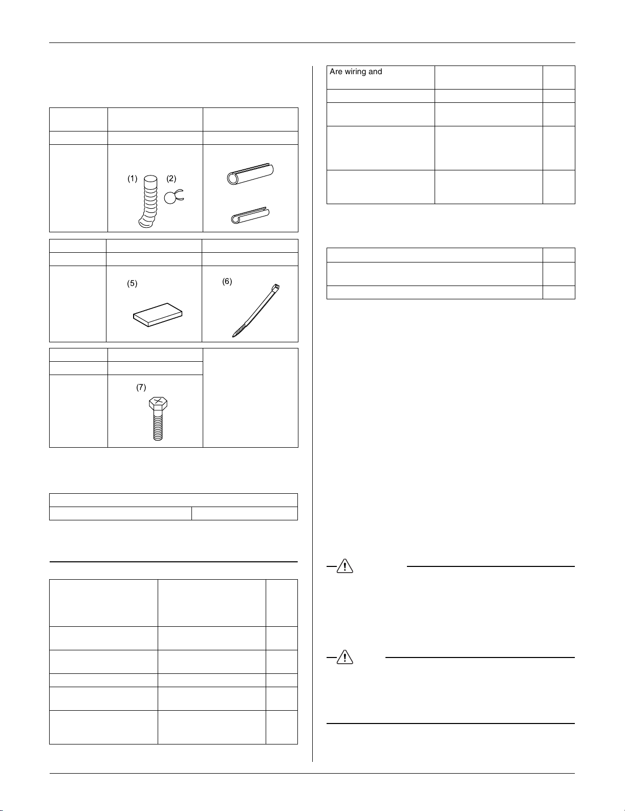
2-1 ACCESSORIES
Check to ensure the following accessories are included
with your unit.
Name Drain hose
Quantity 1 set 1 each
Hose × 1
Metal clamp × 1
Shape
Name Sealing pad Clamp
Quantity 1 pc. 8 pcs.
Shape
Name Leveling screw
Quantity 4 pcs.
Insulation for
fitting
(3)For gas pipe
(4)For liquid pipe
Are wiring and piping correct?
Is the unit safely grounded? Danger of electric leakage.
Is wiring size according to
specifications?
Is something blocking the
air outlet or inlet of either
the indoor or
outdoor units?
Are refrigerant piping length
and additional refrigerant
charge noted down?
Unit may malfunction or the
components burn out.
Unit may malfunction or the
components burn out.
insufficient cooling
Refrigerant charge in the
system is not clear.
b. Items to be checked at time of delivery
Also review the SAFETY CONSIDERATIONS on the previ-
ous page.
Items to be checked:
Did you explain about operations while showing the operation manual to your customer?
Did you hand the operation manual over to your customer?
Check
2-3 NOTE TO THE INSTALLER
Be sure to instruct customers how to properly operate the
unit, especially cleaning filters, operating different functions, and adjusting the temperature.) Have them carry out
operations themselves while looking at the manual.
[Other]
• Operation manual
Shape
• Installation manual
2-2 OPTIONAL ACCESSORIES
Tab l e 1
Remote controller
Wired type BRC1D71
FOR THE FOLLOWING ITEMS, TAKE SPECIAL
CARE DURING CONSTRUCTION AND CHECK
AFTER INSTALLATION IS FINISHED.
a. Items to be checked after completion of work
If not properly done,
Items to be checked:
Are the indoor and
outdoor units fixed firmly?
Is the gas leak test
finished?
Is the unit fully insulated? Dripping condensate water
Does drainage flow
smoothly?
Does the power supply voltage correspond to that
shown on the name plate?
the following can
occur:
Units may drop, vibrate or
make noise.
insufficient cooling
Dripping condensate water
Unit may malfunction or the
components burn out.
Check
3. SELECTING INSTALLATION SITE
• Select an installation site that meets with your cus-
tomer’s approval and where the following conditions
are satisfied: Floor is strong enough to bear the indoor
unit weight.
• Floor is not significantly inclined.
• Nothing blocks the air passage.
• Condensate can be properly drained.
• Sufficient clearance for installation and maintenance
can be ensured.
• Optimum air distribution can be ensured.
• No risk of flammable gas leakage.
• Piping between indoor and outdoor units is possible
within the allowable limit. (Refer to the installation manual of the outdoor unit.)
• If the supporting structural members are not strong enough
to take the unit’s weight, the unit could fall out of place and
cause serious injury.
• Do not install unit in an area where flammable materials are
present due to the risk of explosion resulting in serious
injury or death.
• Install the indoor and outdoor units, power supply wiring
and connecting wires at least 3.5 ft. away from televisions
or radios in order to prevent image interference or noise.
(Depending on the radio waves, a distance of 3.5 ft. may
not be enough to eliminate the noise.)
FXLQ-M / FXNQ-M 18
Page 20
Installation EDUS39-600-F7
Base
FXLQ
Window
4 or
more
(FXLQ)
6 or
more
(FXNQ)
4 or
more
(FXLQ)
3/4 or
more
40 or
more
70 or
more
Air flow direction
Air inlet
direction
Front side
(length : in.)
FXNQ
Maintenance
area
3 1/8 or
more
A or more
B or more
24 5/8
FXNQ12MVJU
FXNQ18 · 24MVJU
A (in.)
28
39
B (in.)
46
57
(IMPORTANT) Leave sufficient clearance for air inlet
and maintenance.
Model
(length :in.)
A
9 3/16 7 9/16
12 type
18 · 24 type
28 3/4
39 3/4
Model A (in.)
1
4
4
5
3
2
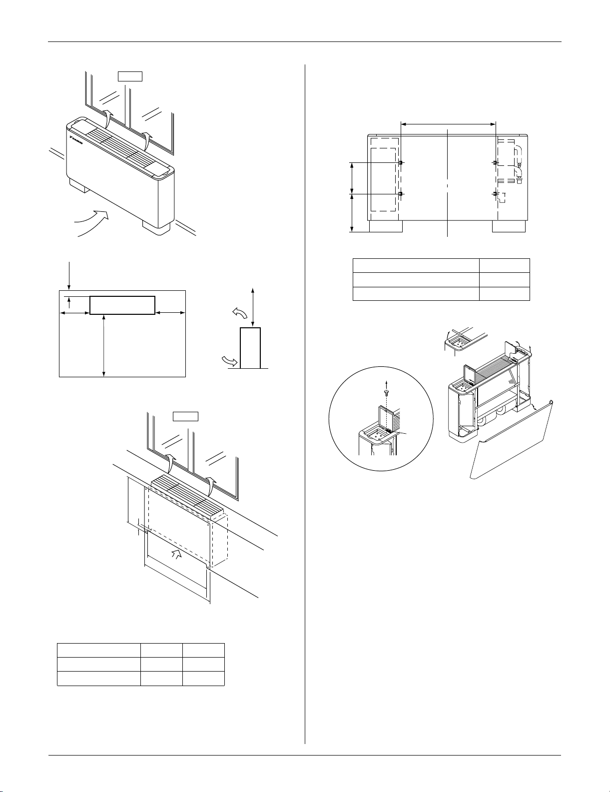
4. PREPARATIONS BEFORE INSTALLATION
(1) Positioning of holes for fastening to the wall
(2) How to open / close the front panel (FXLQ)
19 FXLQ-M / FXNQ-M
1. Open the lid of control panel (both left and right).
2. Remove screws (both left and right)
that lock the knobs in position.
3. Push the knobs (both left and right) to the rear.
4. Lift the front of the top plate.
5. Lower the front panel towards the front of the unit.
• To close, perform the procedure in opposite order by pulling
toward the front of the unit until the knob snaps in place.
Page 21
EDUS39-600-F7_a Installation
NOTE
NOTE
NOTE
Leveling screws (7)
(accessory)
Lift legs.
FXLQ
Lift legs.
FXNQ
Installation
screw
Lower case
of remote
controller
Lid of control
panel
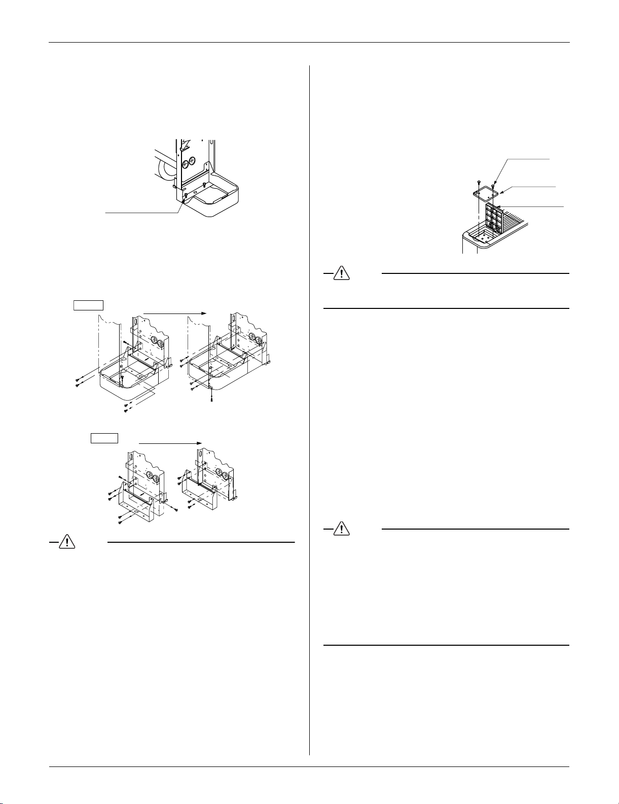
5. INDOOR UNIT INSTALLATION
As for the parts to be used for installation work, be sure to use
the provided accessories and specific Daikin parts.
(1) Level the indoor unit with the leveling screws (7). If
the floor is too uneven to level the unit, place the unit
on a flat surface and level it.
(2) If the unit is in danger of falling over, either fasten to
the wall using the holes provided, or fasten to the
floor with an optional floor fastener.
(3) The legs can be retracted if the indoor unit is to be
hung on a wall. To do so, lift the legs as shown in the
following figure.
(4) Perform the following procedure to mount the
optional remote controller on the unit if desired.
(FXLQ type only)
(5) Open the left side of control panel and mount the
lower case of the remote controller.
•
See the installation manual
attached to the remote controller for instructions on fastening
screws and wiring the remote
controller.
• Setting the unit at an angle opposite to the drain piping
might cause leaks.
6. REFRIGERANT PIPING WORK
For refrigerant piping of outdoor units, see the installation manual attached to the outdoor unit.
Execute heat insulation work completely on both sides of
the gas piping and the liquid piping. Otherwise, a water
leakage can result.
When using a heat pump, the temperature of the gas piping
can reach up to approximately 250°F, so use sufficiently resistant insulation.
In cases where the temperature and humidity of the
refrigerant piping sections might exceed 86°F or RH80%,
reinforce the refrigerant insulation by 13/16” or thicker.
Condensate may form on the surface of the insulating
material.
Before refrigerant piping work, check which type of refrigerant is used. Proper operation is not possible if the types
of refrigerant are not the same.
• Use the installation mount for installation. Check whether
the wall is strong enough to bear the weight of the unit or
not. If there is a risk, reinforce the wall before installing the
unit.
• The unit requires a minimum 2.5 inch clearance on the
underside for air intake. Ensure the unit is level when
installed so that drainage flows smoothly. If tilted or on an
incline, water can leak.
• Operating sound may be louder if installed on a more solid
wall.
FXLQ-M / FXNQ-M 20
• Use a pipe cutter and flare suitable for the type of refrigerant.
• To prevent dust, moisture or other foreign matter from
infiltrating the tube, either pinch the end or cover it with
tape.
• Do not allow anything other than the designated refrigerant to get mixed into the refrigerant circuit, such as
air, etc.
• If any refrigerant gas leaks while working on the unit,
immediately ventilate the room.
When connecting refrigerant piping:
• Ensure that theoutdoor unit is charged with refrigerant.
• Use copper alloy seamless pipes.
• To prevent flare nut cracking and gas leaks, be sure to use
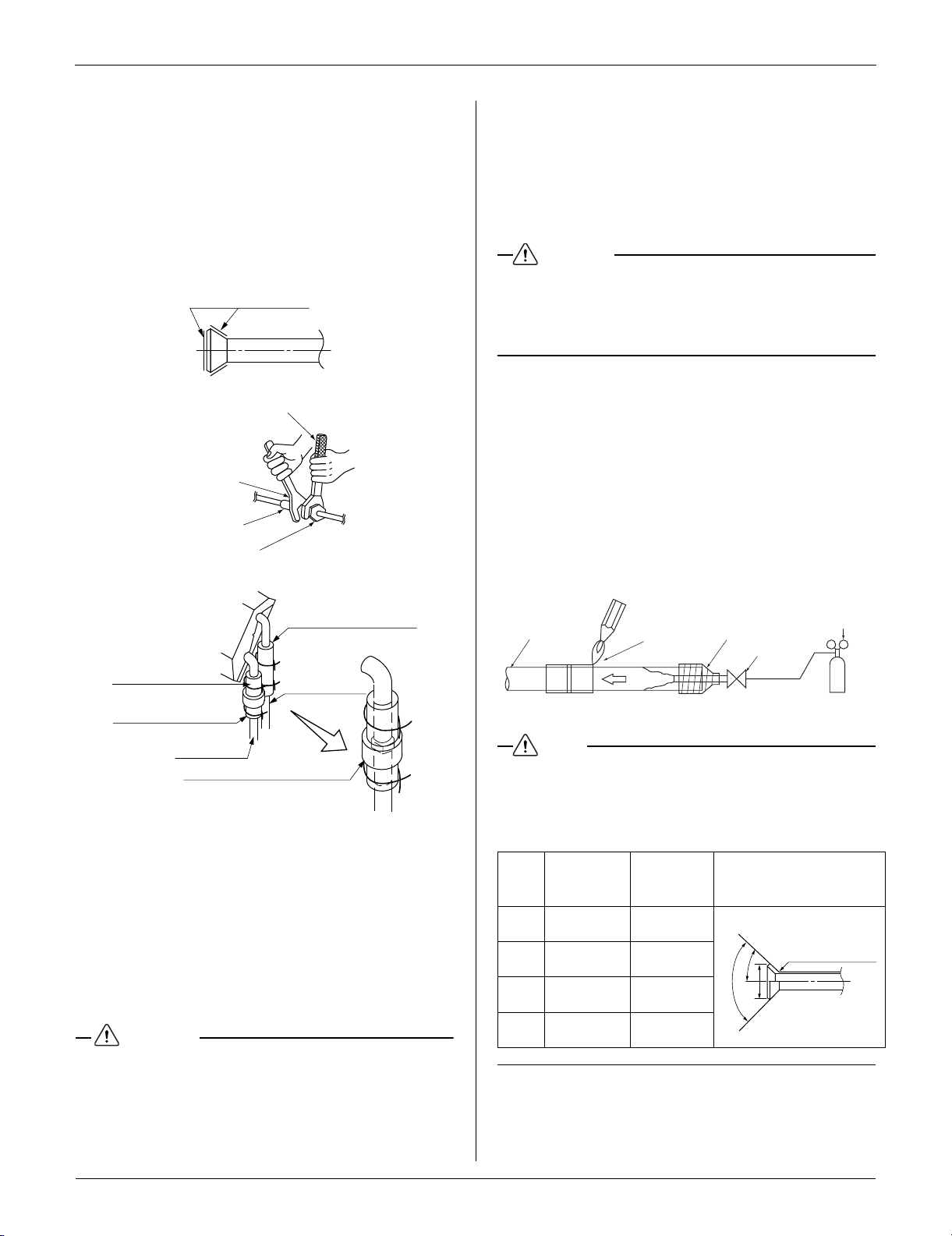
both a spanner and torque wrench together, as shown in
the drawing, when connecting or disconnecting pipes to /
from the unit.
• Refer to Table 2 for the dimensions of flare.
Page 22
Installation EDUS39-600-F7
CAUTION
DANGER
NOTE
Ester oil or ether oil.
Torque wrench
Spanner
Piping union
Flare nut
Insulation for fitting
(accessory) (4)
(For liquid pipe)
Clamp (6)
(accessory)
Insulation for fitting
(accessory) (3)
(For gas pipe)
Sealing pad (accessory) (5)
(Wrapped over union)
Gas pipe
Liquid pipe
Fig. 1
Refrigerant
piping
Part to be
brazed
Taping
Pressurereducing
valve
hands valve
Nitrogen
Nitrogen
45˚± 2˚
90˚± 2˚
R 0.016 ~ 0.031
A
• When connecting the flare nut, coat the flare section (both
inside and outside) with ester oil or ether oil, rotate three or
four times first, then screw in.
• Refer to the Table 2 for tightening torque.
• After inspecting pipe joints for gas leakage, be sure to insulate with the accessory joint insulation for fitting (3) (4) while
referring to the figure below. Fasten both ends with clamps
(6).
Wrap only the gas line side with the sealing pad (5). Bend
the pad over the insulation for fitting (union) from above.
• CAUTION TO BE TAKEN WHEN BRAZING REFRIGERANT PIPING
Do not use flux when brazing refrigerant piping. Therefore,
use the phosphor copper brazing filter metal (BCuP) which
does not require flux.
Flux has an extremely negative effect on refrigerant piping
systems. For instance, if chlorine based flux is used, it will
cause pipe corrosion. If the flux contains fluorine, it will
damage the refrigerant oil.
• Use of oxygen may cause an explosion resulting in serious
injury or death. Only use nitrogen gas.
• Refrigerant gas may produce toxic gas if it comes in contact
with fire such as from a fan heater, stove or cooking device.
Exposure to this gas could cause severe injury or death.
• Before brazing local refrigerant piping, nitrogen gas shall
be blown through the piping to expel air from the piping.
If brazing is done without nitrogen gas blowing, a large
amount of oxide film develops inside the piping, and could
cause system malfunction.
• When brazing the refrigerant piping, only begin brazing
after having carried out nitrogen substitution or while
inserting nitrogen into the refrigerant piping. Once this is
done, connect the indoor unit with a flared or a flanged connection.
• Nitrogen should be set to 2.9 psi with a pressure-reducing
valve if brazing while inserting nitrogen into the piping.
Use Table 3 as a reference if a torque wrench is not available.
Once work is complete, make sure there is no gas leaking. As
the flare nut is tightened with the wrench, the torque suddenly
increases. From that position, tighten the nut to the angle
shown on Table 3 .
• Make absolutely sure to execute heat insulation works on
the pipe-connecting section after checking gas leakage by
thoroughly studying the following figure and using the
attached heat insulating materials for fitting (3) and (4).
(Fasten both ends with the clamps (6) (accessory).) (Refer
to Fig. 1)
• Be sure to insulate any field piping all the way to the piping
connection inside the unit. Any exposed piping may cause
condensate or burns if touched.
21 FXLQ-M / FXNQ-M
Use the flare nuts attached with the unit. Not recommended but if no torque wrench is available, refer
to table 2 for tightening torque:
Tab l e 2
Pipe
size
φ 1/4” 10.5 – 12.7 0.343 – 0.358
φ 3/8” 24.1 – 29.4 0.504 – 0.520
φ 1/2” 36.5 – 44.5 0.638 – 0.654
φ 5/8” 45.6 – 55.6 0.760 – 0.776
Tightening
torque
(ft-lbf)
Flare
dimensions
A (in.)
Flare shape (in.)
Page 23
EDUS39-600-F7_a Installation
CAUTION
DANGER
3/4 drain pipe
2 or more
Drip pan
Metal clamp
(accessory) (2)
Drain hose
(accessory) (1)
Cut to suitable length
(length : in.)
Piping process
inside unit
Tilt
Slope downwards at a gradient
of at least 1/100
Not recommendable but in case of emergency
You must use a torque wrench but if one is not available,
you may follow the installation method mentioned below.
After the work is finished, make sure to check that
there is no gas leak.
When you keep on tightening the flare nut with a spanner,
• Drain piping connections
Do not connect the drain piping directly to sewage pipes
that smell of ammonia. The ammonia in the sewage might
enter the indoor unit through the drain pipes and corrode
the heat exchanger.
• Keep in mind that water collecting on the drain pipe causes
blockage.
there is a point where the tightening torque suddenly
increases. From that position, further tighten the flare nut at
the angle shown below:
Tab l e 3
Pipe size
φ 1/4” 60 to 90 degrees Approx. 5 7/8
φ 3/8” 60 to 90 degrees Approx. 7 7/8
φ 1/2” 30 to 60 degrees Approx. 9 13/16
φ 5/8” 30 to 60 degrees Approx. 11 13/16
Further tightening
angle
Recommended arm length
(in.)
of tool
8. ELECTRIC WIRING WORK
8-1 GENERAL INSTRUCTIONS
• All field supplied parts and materials, electric works must
conform to local codes.
• Use copper wire only.
• Follow the WIRING DIAGRAM attached to the unit to wire
the outdoor unit, indoor units and the remote controllers.
For details on hooking up the remote controller, refer to the
INSTALLATION MANUAL OF REMOTE CONTROLELR.
• All wiring must be performed by an authorized electrician.
• This system consists of multiple indoor units. Mark each
indoor unit as unit A, unit B, and so forth, and be sure the
7. DRAIN PIPING WORK
Install the drain pipe as shown below and take measures
against condensate. Improperly installed piping can
leak on furniture and belongings.
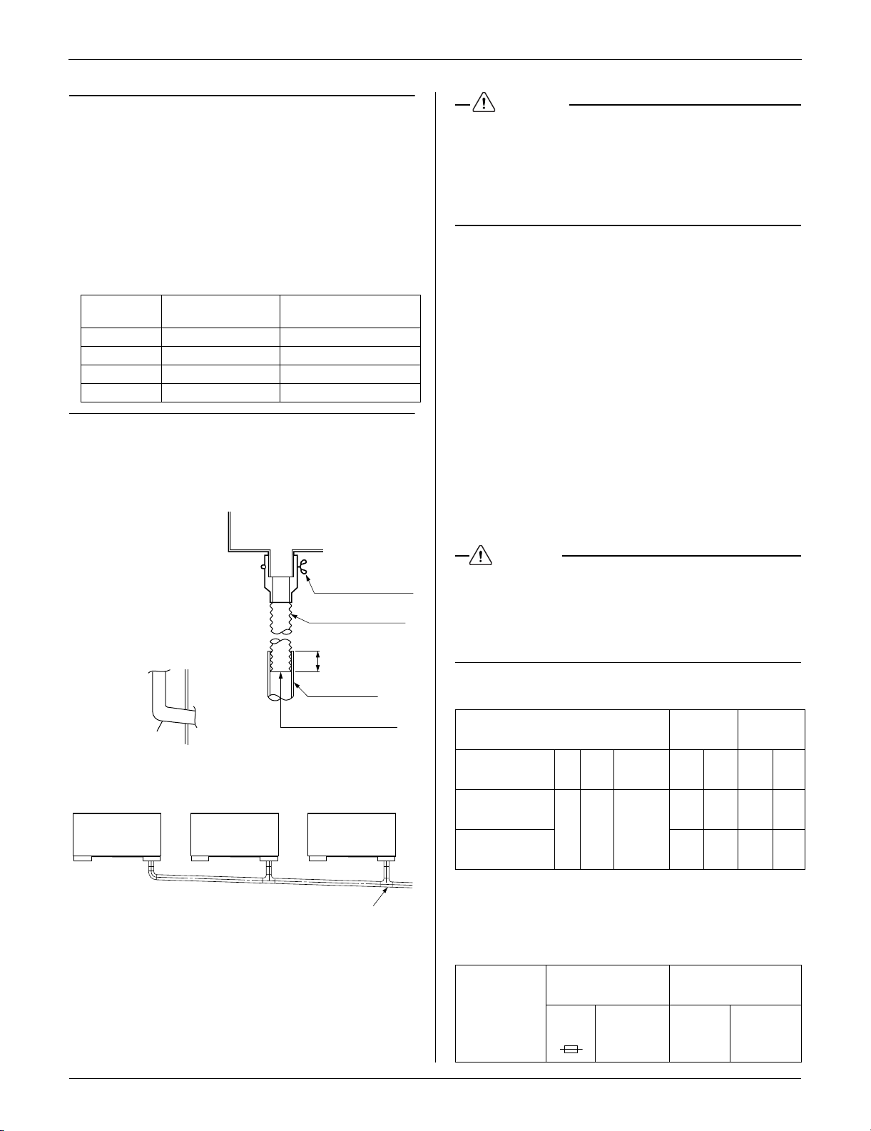
(1) Install the drain pip-
ing:
terminal block wiring to the outdoor unit and BS unit is properly matched. If controls wiring and piping between the
outdoor and indoor units are mismatched, a communications malfunction is likely. A circuit breaker capable of shut-
ting down the power supply to the entire system must be
installed.
• Be sure to ground the air conditioner.
Connect the drain
hose (1) using the
attached hose and
parts, as shown in the
drawing to the right.
• Do not ground units to water pipes, telephone wires, or
lightning rods because incomplete grounding and lighting
strikes can cause a severe shock hazard resulting in
severe injury or death., Do not ground units to gas pipes
because a gas leak can result in an explosion leading to
severe injury or death.
8-2 ELECTRICAL CHARACTERISTICS
Power
supply
MCA MFA W FLA
0.5 15 25 0.4
0.6 15 35 0.5
Fan motor
• If converging multiple drain pipes, install according to the
procedure shown below.
Units
208-
230
Voltage
range
Max. 253
Min. 187
Model Hz Volts
FXLQ12MVJU,
FXNQ12MVJU
60
FXLQ18 · 24MVJU,
FXNQ18 · 24MVJU
MCA: Min. Circuit Amps (A); MFA: Max. Fuse Amps (A)
W: Fan Motor Rated Output (W); FLA: Full Load Amps (A)
8-3 SPECIFICATIONS FOR FIELD SUPPLIED
Select converging drain pipes with gauges suitable for the
operating capacity of the unit.
(2) After piping work is finished, check that drainage flows
smoothly.
• Add approximately 1 liter of water slowly from the air
outlet and check drainage flow.
(3) Be sure to insulate all indoor pipes
FXLQ-M / FXNQ-M 22
FUSES AND WIRE
Power supply wiring
Model
Field
fuses
Remote controller wiring
Transmission wiring
Size Wire Size
Page 24
Installation EDUS39-600-F7
NOTE
NOTE
CAUTION
NOTE
USE COPPLE CONDUCTION
POWER SUPPLY
Electric parts box
Power supply wiring,
ground wiring
(Field wiring)
Remote controller wiring
(Field wiring)
Transmission wiring
(Field wiring)
REMOTE
CNTRL
FORCED
OFF
TRANSMISSION
WIRING
F1
P1
P2
F2
T1
T2
L1
L2
Clamp
fastener
Clamp (6)
(accessory)
Cut off excess
after tightening
Conduit
Lock nut
Pass through hole
of remote
controller
fastening plate.
Remote
controller wiring
FXLQ12 · 18 ·
24 MVJU
FXNQ12 · 18 ·
24 MVJU
15A
Size must
comply with
local codes.
Sheathed
wire
(2 wire)
AWG
18-16
1. Allowable length of transmission wiring between indoor /
outdoor units and between the indoor unit and the remote
controller is as follows.
(1) Outdoor unit – Indoor unit:
Max. 3280 ft. (Total wiring length: 6560 ft.)
(2) Indoor unit – Remote controller:
Max. 1640 ft.
2. Insulated thickness: 1/16” or more.
9. WIRING EXAMPLE AND HOW TO SET
THE REMOTE CONTROLLER
9-1 HOW TO CONNECT WIRINGS
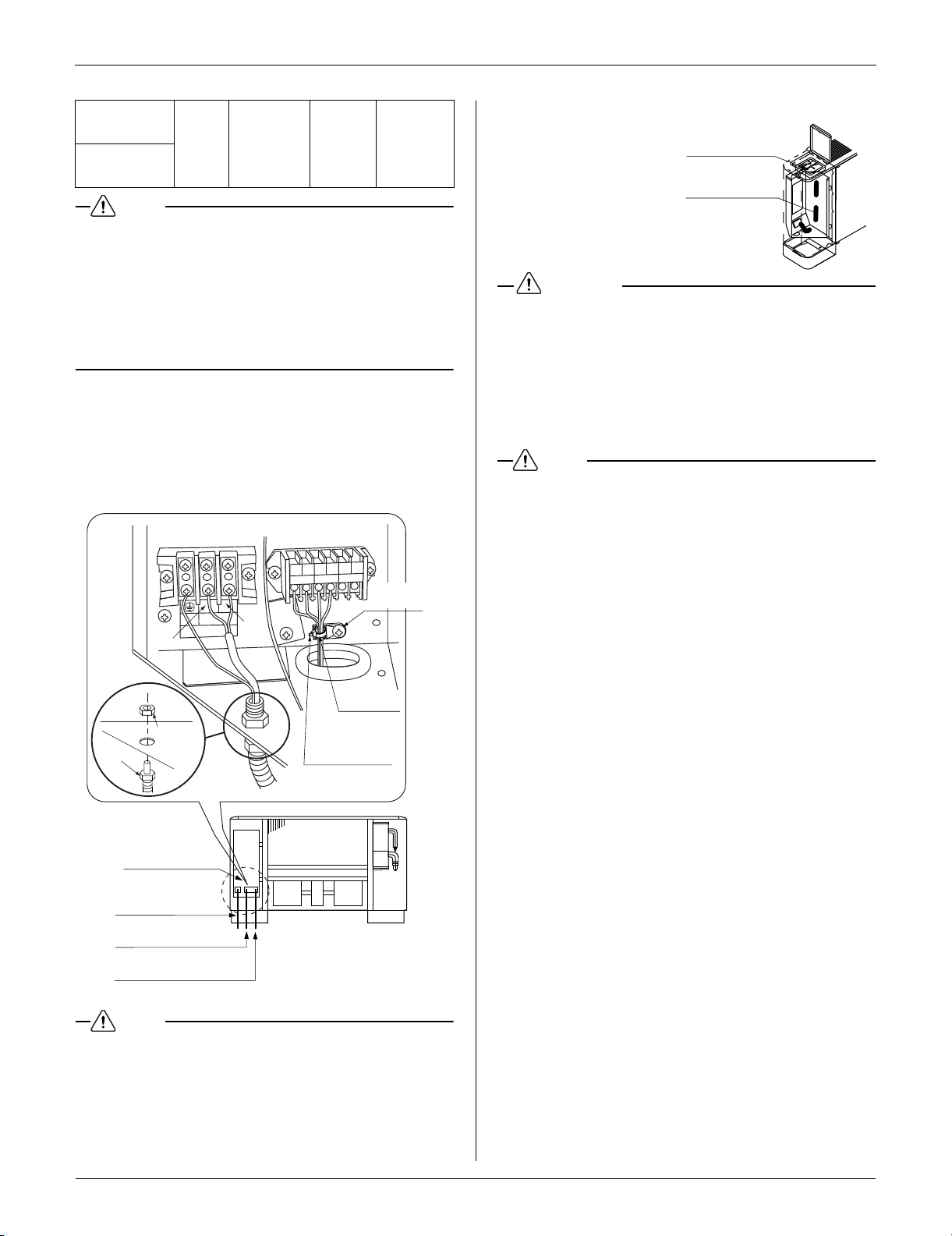
• Remove the electric parts box lid and connect the wirings.
• If mounting a remote
controller on the unit,
wire as shown in the
figure on the right.
• Never connect power supply wiring to the terminal block for
remote controller wiring as this could damage the entire
system.
• Use only specified wire and connect wires to the terminal
tightly. Be careful wires do not place external stress on terminals. Keep wires in neat order so as to not obstruct other
equipment. Make sure that the electric box lid fits tightly.
Incomplete connections could result in overheating and, in
worse case, result in electric shock or fire.
• To avoid a short circuit in the electric parts box, be sure to
apply sealing material or putty (not included) to the wiring
hole to prevent the infiltration of water as well as insects or
other small creatures. Otherwise a short-circuit may occur
inside the electric parts box.
• When clamping the wirings, be sure no tension is applied to
the wire connections by using the included clamps. Also,
when wiring, make sure the electric parts box lid fits snugly
by arranging the wirings neatly and attaching the electric
parts box lid firmly. When attaching the electric parts box
lid, make sure no wirings get caught in the edges. Pass the
wirings through the hole to prevent damage.
• For wiring to the electric parts box, see the WIRING DIA-
GRAM label on the back of the electric parts box lid.
• Do not confuse remote controller wiring and transmission
wiring when connecting to the terminal block.
• Fasten the wiring with accessory clamp (6).
23 FXLQ-M / FXNQ-M
Page 25
EDUS39-600-F7_a Installation
Electric wire
Round crimp-style terminal
Attach insulation sleeve
Power supply wiring
Transmission wiring
Switch
Fuse
Power supply
Main
switch
Remote controller
Indoor unit
BS unit
(Only for
Heat
recovery
system)
L1 L2
IN/D OUT/D
F
1 F2 F1 F2
Control box
P1P
2
P1P
2
F1F2T1T
2
P1P
2
P1P
2
F1F2T1T
2
P1P
2
P1P
2
F1F2T1T2L1L
2
L1L
2
L1L
2
L1L
2
P1P
2
P1P
2
F1F2T1T
2
L1 L2 L1 L2 L1 L2
Outdoor unit
No. 1
System
Indoor
unit A
Indoor
unit B
Indoor
unit C
Most
downstream
indoor unit
Power supply
208-230V
60Hz
Power supply
208-230V
60Hz
Power supply
208-230V
60Hz
Power supply
208-230V
60Hz
IN/D OUT/D
F
1 F2 F1 F2
Control box
P1P
2
P1P
2
F1F2T1T
2
P1P2F1F2T1T
2
P1P2F1F2T1T
2
P1P2F1F2T1T
2
P1P
2
P1P
2
Outdoor unit
No. 2
System
Indoor unit A
Indoor unit B
Indoor unit C
Most
downstream
indoor unit
For use with 2
remote controllers
Note: It is not necessary to designate
indoor unit address when using
group control.
The address is automatically
set when power is activated.
Fig. 2
L1 L2
Power supply
208-230V
60Hz
L1L
2
L1L
2
L1L
2
L1L
2
Make sure the remote controller wiring, the wiring between the
units, and other electric wiring do not pass through the same
locations outside of the unit, separating them by at least 5”, to
prevent the possibility of electric noise (external static) causing faulty operation or breakage.. PRECAUTIONS
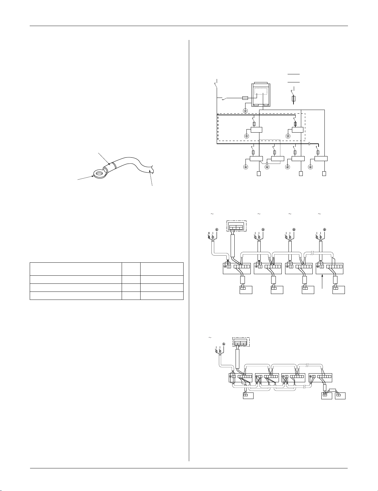
1. Use round crimp-style terminals for connecting wires to
the power supply terminal block.
If unavailable, observe the following points when wiring.
• Do not connect wires of different gauges to the same
power supply terminal. Looseness in the connection
may cause overheating.
• Use the specified electric wire. Connect the wire
securely to the terminal. Lock the wire down without
applying excessive force to the terminal. (Tightening
torque: 0.97ft.lbf ±10 %)
2. Tightening torque for the terminal screws.
• Use the correct screwdriver for tightening the terminal
screws. If the blade of screwdriver is too small, the head
of the screw might be damaged, and the screw will not
be properly tightened.
• If the terminal screws are tightened too hard, they might
be damaged.
• Refer to the table below for the tightening torque of the
terminal screws.
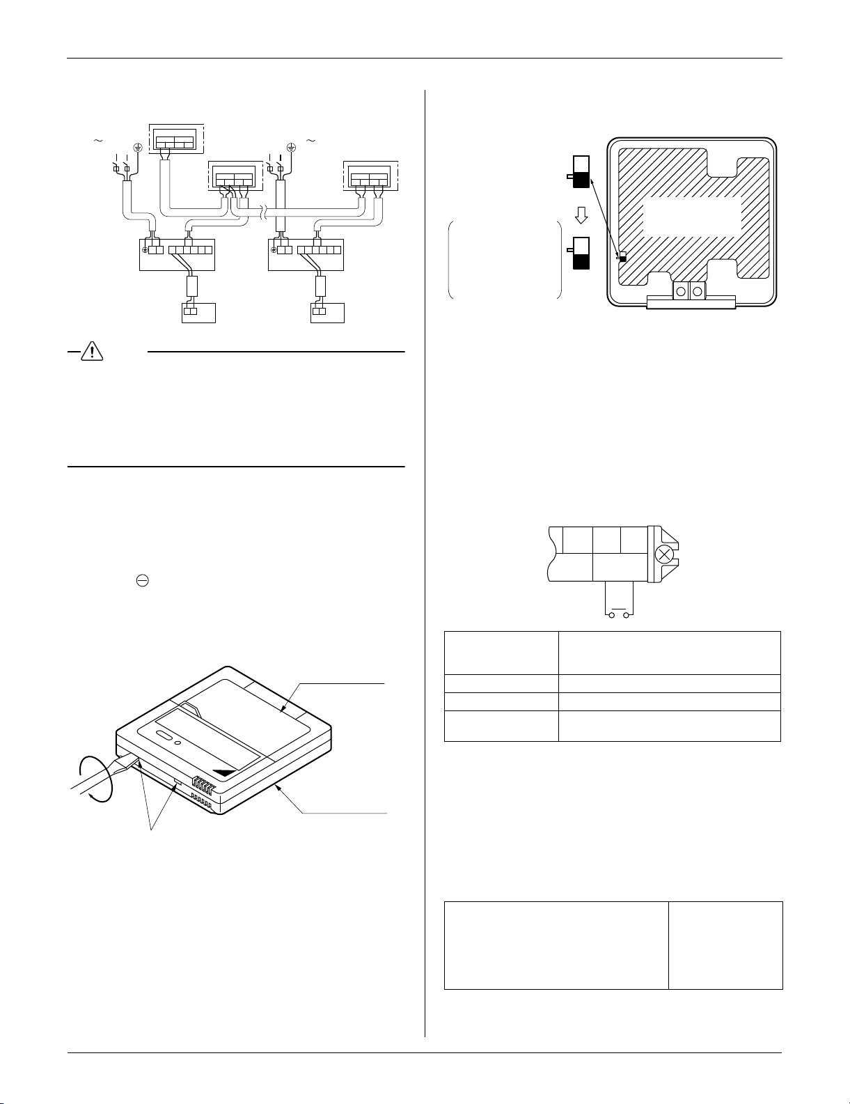
9-2 WIRING EXAMPLE
• Fit the power supply wiring of each unit with a switch and
fuse as shown in the drawing.
COMPLETE SYSTEM EXAMPLE (3 SYSTEMS)
1. When using 1 remote controller for 1 indoor unit.
(Normal operation)
Terminal block for remote controller (6P) M3.5 0.58 – 0.72
Power supply terminal block (2P) M4 0.87 – 1.06
Ground terminal M4 1.06 – 1.43
3. Do not connect wires of different gauge to the same
grounding terminal. Looseness in the connection may
deteriorate protection.
4. Outside of the unit, keep transmission wiring at least 5”
away from power supply wiring. The equipment may malfunction if subjected to electric (external) noise.
5. For remote controller wiring, refer to the INSTALLATION
MANUAL OF REMOTE CONTROLLER.
FXLQ-M / FXNQ-M 24
Terminal Size
Tightening torque
(ft-lbf)
2. For group control or use with 2 remote controllers
Page 26
Installation EDUS39-600-F7
NOTE
IN/D OUT/D
F
1F2F1F2
IN/DOUT/D
F
1F2F1F2
L1L
2
P1P
2
P1P2F1F2T1T
2
BS unit
No. 3
System
Outdoor unit
Indoor unit A
Most
downstream
indoor unit
Control box
Control box
IN/DOUT/D
F
1F2F1F2
BS unit
Control box
L1L
2
P1P
2
P1P2F1F2T1T
2
Power supply
208-230V
60Hz
Power supply
208-230V
60Hz
L1 L2 L1 L2
Upper part of
remote controller
Lower part of
remote controller
Insert the screwdriver here and gently work
off the upper part of remote controller.
S
M
S
S
M
Only one remote
controller needs to
be changed if
factory settings
have remained
untouched.
Remote controller
PC board
(Factory setting)
F2 T1 T2
FORCED
OFF
Input A
3. When including BS unit
1. A single switch can be used to supply power to units on
the same system. However, branch switches and branch
circuit breakers must be selected carefully.
2. Do not ground the equipment on gas pipes, water pipes,
lightning rods or telephone ground wires. Improper
grounding could result in electric shock.
9-3 CONTROLLING 1 INDOOR UNIT BY 2
REMOTE CONTROLLERS
• When using 2 remote controllers, one must be set to
“MAIN” MAIN and the other to SUB.
MAIN/SUB CHANGEOVER
(1) Insert a screwdriver into the recess between the upper
and lower part of remote controller, and working from the
2 positions, pry off the upper part.
The remote controller PC board is attached to the upper
part of remote controller.
(2) Turn the MAIN/SUB changeover switch on one of the two
two remote controllers PC board to [S]. Leave the switch
of the other remote controller set to [M].
Wiring Method (See ‘‘8. ELECTRIC WIRING WORK’’)
(3) Remove the electric parts box lid
(4) Add remote control 2 (slave) to the terminal block for
remote controller (P
, P2) in the electric parts box.
1
There is no polarity. (Refer to Fig. 2 and 8-3.)
9-4 COMPUTERIZED CONTROL (FORCED OFF
AND ON/OFF OPERATION)
(1) Wire specifications and how to perform wiring
• Connect input from outside to terminals T1 and T2 of
the terminal block for remote controller.
Wire specification 2-conductor, stranded, non-shielded copper
Gauge AWG18
Length Max. 328 ft.
External terminal
(2) Actuation
• The following table explains FORCED OFF and ON/
OFF OPERATIONS in response to Input A. The T1-T2
terminals are standard on all Daikin indoor units and
allow for remote starting and stopping of equipment.
Individual indoor units can be field prgrammed at the
remote controller to change the T1-T2 sequence of
operation of the equipment based upon the application..
FORCED OFF (Manual Restart)
Mode No. 12
First Code No. 1
Second Code No. 01
DEFAULT SETTING
cable / PVC or vinyl jacket
Contact that can ensure the minimum
applicable load of 15 V DC, 10 mA.
ON/OFF OPERATION
Mode No. 12
First Code No. 1
Second Code No.
02
25 FXLQ-M / FXNQ-M
Page 27
Installation EDUS39-600-F7_a
SETTING
Mode No.
SECOND
CORD NO.
FIRST
CORD NO.
FIELD SET MODE
Input A OFF (Open Circuit)
An open circuit between terminals T1 and
T2 allows the unit to run normally.
Input A ON (Closed Circuit)
Closing the normally open circuit between
terminals T1 and T2 stops operation of the
unit. When T1-T2 is opened, the unit must
be restarted with the remote controller.
.
Input A OFF (Open
Circuit)
An open circuit
between terminals
T1 and T2 prevents
unit operation.
Input A ON (Closed
Circuit)
A closed circuit
between terminals
T1 and T2 allows
normal operation of
the unit.
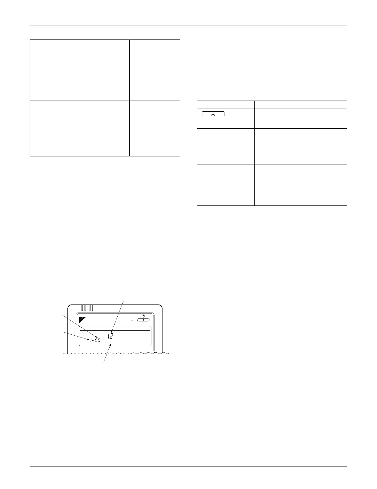
(3) How to select FORCED OFF and ON/OFF
• Turn the power on and then use the remote controller to
select operation. These codes are programmed at the
remote controller. Individual unit groups can be programmed independently.
9-5 CENTRALIZED CONTROL
• For centralized control, it is necessary to designate the
group No. For details, refer to the manual of each optional
controller for centralized control.
• The operation lamp of the remote controller flashes when
a malfunction occurs. Check the malfunction code on the
liquid crystal display to identify the point of trouble. An
explanation of malfunction codes and the corresponding
trouble is provided in the installation manual of the outdoor
unit.
If any of the items in Table 4 are displayed, there may be a
problem with the wiring or power, so check the wiring again.
Tab l e 4
Remote control display Content
Under Cen-
tralized Control
is lit
U4 is lit
UH is lit
No display
• There is a short circuit at the
FORCED OFF terminals (T1, T2)
• The power on the outdoor unit is off.
• The outdoor unit has not been wired
for power supply.
• Incorrect wiring for the transmission
wiring and / or FORCED OFF wiring.
• The transmission wiring is cut.
• The power on the indoor unit is off.
• The indoor unit has not been wired
for power supply.
• Incorrect wiring for the remote controller wiring, the transmission wiring
and / or the FORCED OFF wiring.
• The remote controller wiring is cut.
•If U3 is lit , the malfunction code shows the test operation
has not been performed yet.
10. FIELD SETTING
Make sure the electric parts box lids are closed on the
indoor and outdoor units.
Field setting must be made from the remote controller in
accordance with the installation condition.
• Setting can be made by changing the Mode No., FIRST
CODE NO., and SECOND CODE NO.
• For setting and operation, refer to the FIELD SETTING
section in the installation manual of the remote controller.
• Set the remote controller to the field set mode. For
details, refer to HOW TO SET IN THE FIELD in the
remote controller manual.
• When in the field set mode, select mode No. 12, then
set the first code (switch) No. to [1]. Then set second
code (position) No. to [01] for FORCED OFF and [02]
for ON / OFF OPERATION. (FORCED OFF at factory
set)
11. TEST OPERATION
Make sure the service lids are closed on the indoor and outdoor units.
Refer to the installation manual of the outdoor unit.
26 FXLQ-M / FXNQ-M
Page 28
EDUS39-600-F7_a Accessories
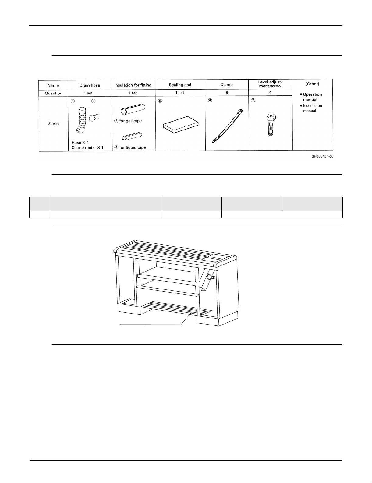
Long Life Replacement Filter
(V0683)
10.Accessories
Standard Accessories
Optional Accessories (For Unit)
No.
Item
1 Long life replacement filter KAFJ361K45 KAFJ361K71
Type
FXLQ12MVJU
FXNQ12MVJU
FXLQ18MVJU
FXNQ18MVJU
For Controller Optional Accessories,Refer to Controller Manual.
FXLQ24MVJU
FXNQ24MVJU
4D045647
FXLQ-M / FXNQ-M 27
Page 29

Accessories EDUS39-600-F7_a
28 FXLQ-M / FXNQ-M
Page 30
May 2007
AMERICAS
1645 Wallace Drive, Suite 110
Carrollton, TX75006
www.daikinac.com
EDUS39-600-F7_a
Printed in U.S.A. 05/2007
 Loading...