

Daikin FXFQ25PVE, FXFQ63PVE, FXFQ80PVE, FXFQ40PVE, FXFQ100PVE Installation Manual
...
INSTALLATION MANUAL
SYSTEM Inverter Air Conditioners
MODELS
Ceiling mounted cassette type (Round flow model)
FXFQ25PVE FXFQ63PVE
FXFQ32PVE FXFQ80PVE
FXFQ40PVE FXFQ100PVE
FXFQ50PVE FXFQ125PVE
English
Español
Portugues
READ THESE INSTRUCTIONS CAREFULLY BEFORE INSTALLATION.
KEEP THIS MANUAL IN A HANDY PLACE FOR FUTURE REFERENCE.
LEA CUIDADOSAMENTE ESTAS INSTRUCCIONES ANTES DE INSTALAR.
GUARDE ESTE MANUAL EN UN LUGAR A MANO PARA LEER EN CASO DE TENER
ALGUNA DUDA.
LEIA COM ATENÇÃO ESTAS INSTRUÇÕES ANTES DE REALIZAR A INSTALAÇÃO.
MANTENHA ESTE MANUAL AO SEU ALCANCE PARA FUTURAS CONSULTAS.
FXFQ25PVE
FXFQ32PVE
FXFQ40PVE
FXFQ50PVE
FXFQ63PVE
FXFQ80PVE
FXFQ100PVE
FXFQ125PVE
VRV SYSTEM Inverter
Air Conditioners
Installation manual
CONTENTS
1. SAFETY PRECAUTIONS ..............................................................................................1
2. BEFORE INSTALLATION..............................................................................................3
3. SELECTING INSTALLATION SITE ............................................................................... 5
4. PREPARATIONS BEFORE INSTALLATION.................................................................7
5. INDOOR UNIT INSTALLATION.....................................................................................8
6. REFRIGERANT PIPING WORK .................................................................................. 10
7. DRAIN PIPING WORK................................................................................................. 12
8. ELECTRIC WIRING WORK.........................................................................................15
9. WIRING EXAMPLE AND HOW TO SET THE REMOTE CONTROLLER ...................16
10. INSTALLATION OF THE DECORATION PANEL .......................................................... 22
11. FIELD SETTING...........................................................................................................22
12. TEST OPERATION......................................................................................................24
1. SAFETY PRECAUTIONS
Please read these “SAFETY PRECAUTIONS” carefully before installing air conditioning unit and be sure to
install it correctly. After completing installation, conduct a trial operation to check for faults and explain to the
customer how to operate the air conditioner and take care of it with the aid of the operation manual. Ask the
customer to store the installation manual along with the operation manual for future reference.
This air conditioner comes under the term “appliances not accessible to the general public”.
This unit is a class A product. In a domestic environment this product may cause radio interference in which
case the user may be required to take adequate measures.
Meaning of WARNING and CAUTION notices.
WARNING .........Failure to follow these instructions properly may result in personal injury or loss of life.
CAUTION ..........Failure to observe these instructions properly may result in property damage or per-
sonal injury, which may be serious depending on the circumstances.
WARNING
• Ask your dealer or qualified personnel to carry out installation work.
Do not attempt to install the air conditioner yourself. Improper installation may result in water leakage,
electric shocks or fire.
• Install the air conditioner in accordance with the instructions in this installation manual.
Improper installation may result in water leakage, electric shocks or fire.
• Consult your local dealer regarding what to do in case of refrigerant leakage.
When the air conditioner is to be installed in a small room, it is necessary to take proper measures so that
the amount of any leaked refrigerant does not exceed the concentration limit in the event of a leakage. Otherwise, this may lead to an accident due to oxygen depletion.
1 English
• Be sure to use only the specified accessories and parts for installation work.
Failure to use the specified parts may result in the unit falling, water leakage, electric shocks or fire.
• Install the air conditioner on a foundation strong enough to withstand the weight of the unit.
A foundation of insufficient strength may result in the equipment falling and causing injury.
• Carry out the specified installation work after taking into account strong winds, typhoons or earthquakes.
Failure to do so during installation work may result in the unit falling and causing accidents.
• Make sure that a separate power supply circuit is provided for this unit and that all electrical work is carried
out by qualified personnel according to local laws and regulations and this installation manual.
An insufficient power supply capacity or improper electrical construction may lead to electric shocks or fire.
• Make sure that all wiring is secured, the specified wires are used, and that there is no strain on the terminal
connections or wires.
Improper connections or securing of wires may result in abnormal heat build-up or fire.
When wiring the power supply and connecting the remote controller wiring and transmission wiring, position
•
the wires so that the terminal box lid can be securely fastened.
Improper positioning of the terminal box lid may result in electric shocks, fire or the terminals overheating.
• If refrigerant gas leaks during installation, ventilate the area immediately.
Toxic gas may be produced if the refrigerant comes into contact with fire.
• After completing installation, check for refrigerant gas leakage.
Toxic gas may be produced if the refrigerant gas leaks into the room and comes into contact with a source
of fire, such as a fan heater, stove or cooker.
• Be sure to switch off the unit before touching any electrical parts.
• Do not directly touch refrigerant that has leaked from refrigerant pipes or other areas, as there is a danger
of frostbite.
• Be sure to earth the air conditioner.
Do not earth the unit to a utility pipe, lightning conductor or telephone earth lead.
Imperfect earthing may result in electric shocks or fire.
A high surge current from lightning or other sources may cause damage to the air conditioner.
• Be sure to install an earth leakage breaker.
Failure to install an earth leakage breaker may result in electric shocks or fire.
CAUTION
• While following the instructions in this installation manual, install drain piping to ensure proper drainage and
insulate piping to prevent condensation.
Improper drain piping may result in indoor water leakage and property damage.
• Install the indoor and outdoor units, power cord and connecting wires at least 1 meter away from televisions
or radios to prevent picture interference and noise.
(Depending on the incoming signal strength, a distance of 1 meter may not be sufficient to eliminate noise.)
• Remote controller (wireless kit) transmitting distance can be shorter than expected in rooms with electronic
fluorescent lamps (inverter or rapid start types).
Install the indoor unit as far away from fluorescent lamps as possible.
• Do not install the air conditioner in the following locations:
1. Where there is a high concentration of mineral oil spray or vapour (e.g. a kitchen).
Plastic parts will deteriorate, parts may fall off and water leakage could result.
2. Where corrosive gas, such as sulphurous acid gas, is produced.
Corroding of copper pipes or soldered parts may result in refrigerant leakage.
3. Near machinery emitting electromagnetic radiation.
Electromagnetic radiation may disturb the operation of the control system and result in a malfunction of
the unit.
4. Where flammable gas may leak, where there is carbon fibre or ignitable dust suspensions in the air, or
where volatile flammables such as paint thinner or gasoline are handled.
Operating the unit in such conditions may result in fire.
English 2
2. BEFORE INSTALLATION
Do not exert pressure on the resin parts when opening the unit or when moving it after opening
Be sure to check the type of R410A refrigerant to be used before doing any work. (Using an incorrect
refrigerant will prevent normal operation of the unit.)
• When opening the unit or moving it after opening, be sure to lift it by holding on to the lifting lugs without
exerting any pressure on other parts, especially, drain piping, and other resin parts.
• Decide upon a line of transport.
• Leave the unit inside its packaging while moving, until reaching the installation site. Use a sling of soft mate-
rial, where unpacking is unavoidable or protective plates together with a rope when lifting, to avoid damage
or scratches to the unit.
• Refer to the installation manual of the outdoor unit for items not described in this manual.
• Do not dispose of any parts necessary for installation until the installation is complete.
1. PRECAUTIONS
• Be sure to read this manual before installing the indoor unit.
• When selecting installation site, refer to the paper pattern.
• This unit is suitable for installation in a household, commercial and light industrial environment.
• Do not install or operate the unit in rooms mentioned below.
• Laden with mineral oil, or filled with oil vapor or spray like in kitchens. (Plastic parts may deteriorate.)
• Where corrosive gas like sulfurous gas exists. (Copper tubing and brazed spots may corrode.)
• Where volatile flammable gas like thinner or gasoline is used.
• Where machines can generate electromagnetic waves. (Control system may malfunction.)
• Where the air contains high levels of salt such as that near the ocean and where voltage fluctuates
greatly such as that in factories. Also in vehicles or vessels.
2. ACCESSORIES
Check the following accessories are included with your unit.
(3) Washer for
Name (1) Drain hose (2) Metal clamp
Quantity 1 pc. 1 pc. 8 pcs. 6 pcs. 1 pc. 4 pcs.
Shape
Name
Quantity 4 pcs. 1 each 1 each 1 pc. 1 pc. 1 pc.
Shape
(7) Washer
fixing plate
Insulation for
fitting
(8) for gas
pipe
(11) Medium-1
(9) for liquid
pipe
(12) Medium-2
hanger
bracket
(10) Large
(4) Clamp
Sealing pad Installation guide
(13) Small
(14)
(5) Paper pattern for
installation
Also used as packing material
(15)
(6) Screw (M4)
For paper pattern
for installation
(Other)
•
•
Installation
manual
Operation
manual
3 English

3. OPTIONAL ACCESSORIES
• The optional decoration panel and remote controller are required for this indoor unit. (Refer to Table 1, 2)
(However, the remote controller is not required for the slave unit of a simultaneous operation system.)
Ta ble 1
Unit model Optional decoration panel
FXFQ25 · 32 · 40 · 50 · 63 · 80 · 100 · 125PVE
• These are two types of remote controllers: wired and wireless. Select a remote controller from Table 2
according to customer request and install in an appropriate place.
Ta ble 2
Remote controller
Wired type BRC1C62
Wireless type (Heat pump type/Cooling only type) BRC7F634F/BRC7F635F
NOTE
• If you wish to use a remote controller that is not listed in “Table 2” on page 4, select a suitable remote con-
troller after consulting catalogs and technical materials.
BYCP125K-W1
Color : Fresh white
FOR THE FOLLOWING ITEMS, TAKE SPECIAL CARE DURING CONSTRUCTION AND
CHECK AFTER INSTALLATION IS FINISHED.
1. Items to be checked after completion of work
Items to be checked If not properly done, what is likely to occur Check
Are the indoor unit and outdoor unit fixed
firmly?
Is the outdoor unit fully installed?
Is the gas leak test finished? It may result in insufficient cooling.
Is the unit fully insulated? Condensate water may drip.
Does drainage flow smoothly? Condensate water may drip.
Does the power supply voltage correspond
to that shown on the name plate?
Are wiring and piping correct?
Is the unit safely grounded? It may result in electric shock.
Is wiring size according to specifications?
Is something blocking the air outlet or inlet
of either the indoor or outdoor units?
Are refrigerant piping length and additional
refrigerant charge noted down?
The unit may drop, vibrate or make noise.
The unit may malfunction or the components burn out.
The unit may malfunction or the components burn out.
The unit may malfunction or the components burn out.
The unit may malfunction or the components burn out.
It may result in insufficient cooling.
The refrigerant charge in the system is not
clear.
2. Items to be checked at time of delivery
* Also review the “1. SAFETY PRECAUTIONS”
Items to be checked Check
Are the terminal box lid, air filter, suction grille attached?
Did you explain about operations while showing the instruction manual to your customer?
Did you hand the instruction manual over to your customer?
English 4
Points for explanation about operations
The items with WARNING and CAUTION marks in the instruction manual are the items pertaining to possibilities for bodily injury and material damage in addition to the general usage of
the product. Accordingly, it is necessary that you make a full explanation about the described contents and also ask your customers to read the instruction manual.
4. NOTE TO THE INSTALLER
Be sure to instruct customers how to properly operate the unit (especially cleaning filters, operating different
functions, and adjusting the temperature) by having them carry out operations themselves while looking at the
manual.
3. SELECTING INSTALLATION SITE
〈Hold the unit by the 4 lifting lugs when opening the box and moving it, and do not exert pressure on to any
other part piping (refrigerant, drain, etc.) or plastic parts.
If the temperature or humidity inside the ceiling might rise above 30°C or RH 80%, respectively, use the highhumidity kit (sold separately) or add extra insulation to the main unit body.
Use glass wool or polyethylene foam as insulation and make sure it is at least 10mm thick and fits inside the
ceiling opening.〉
The direction this product blows can be selected. However, a separately sold shut-off material kit is
needed in order to make the unit blow in two, three, or four (corner shut-off) directions.
(1) Select an installation location with the customer’s approval which matches the following conditions.
• A location from which cool (warm) air will reach the whole room.
• A location with no objects blocking the air passage.
• A location where drainage can be done with no problem.
• A location strong enough to support the weight of the indoor unit.
• Locations where the wall is not significantly tilted.
• A location which leaves enough room for installation and service work.
• A location where there is no risk of flammable gas leaking.
• A location where the length of the indoor-outdoor piping is no longer than the tolerated length (see the
installation manual that came with the outdoor unit for details).
[Space required for installation]
*≥1500
H
Air
discharge
At least 1800mm
from the floor.
FXFQ25 · 32 · 40 · 50 · 63 · 80PVE 256
FXFQ100 · 125PVE 298
5 English
≥
1500
Floor surface
Model H (mm)
Air
inlet
Fig. 1
Air
discharge
≥
1500
*≥1500
*≥1500
*≥1500
Fig. 2
CAUTION
• The indoor and outdoor units and the power supply wiring and remote controller cord must be installed
at least 1m away from any televisions or radios. This is to prevent interference with picture and sound
reception. (Interference may occur even at 1m away depending on the reception quality.)
• If installing the wireless kit, the distance of the signal sent from the remote controller might be shorter if
there are fluorescent lights which are electrically started (such as with inverters, rapid starters, etc.) in
the room. The indoor unit should be installed as far away from fluorescent lights as possible.
(2) Ceiling height
This product can be installed in ceilings up to 3.5m high (4.2m high for the 100 and 125).
If the ceiling height is 2.7m (3.2m for the 100 and 125) or more, field settings will have to be made with the
remote controller. See “11. FIELD SETTING” for details.
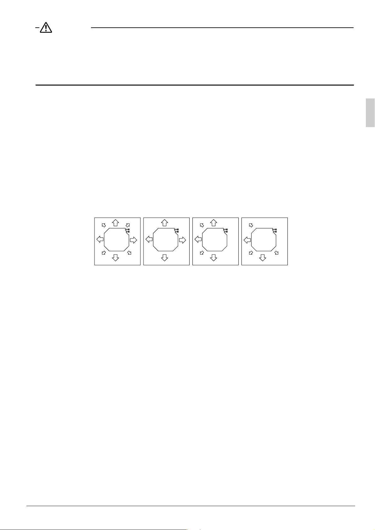
(3) Air direction
The air direction shown in Fig. 3 is an example.
Select the appropriate number of directions according to the shape of the room and the location of the unit.
(Field settings have to be made using the remote controller and the outlet vents have to be shut off if two,
three, or four (corner shut-off) directions are selected. See the shut-off materials (sold separately) installation manual for details.)
(4) Use eyebolts for installation. Check if the location for the installation is strong enough to support the weight
of the unit, reinforce it if necessary, and install using eyebolts. (The spacing of the installation is shown on
the “paper pattern for installation (5)”.)
All-round air
[Air direction]
Pipes
Four air direction
Pipes
Three air direction
Fig. 3
Pipes
Two air direction
Pipes
English 6

4. PREPARATIONS BEFORE INSTALLATION
(1) Relation of ceiling opening to unit and suspension bolt position.
Refrigerant
piping
Suspension
bolt (×4)
910 (Ceiling opening)
840 (Indoor unit)
–
950 (Decoration panel)
860
䡵 Installation is possible when ceiling opening dimensions is as follows
• When installing the unit within the frame for fixing false ceiling.
780 (Suspension bolt pitch)
710(Suspension bolt pitch)
840 (Indoor unit)
860 – 910 (Ceiling opening)
950 (Decoration panel)
A
Fig. 4
False
ceiling
View as seen from A
Fig. 5
Hanger
bracket
130
–
125
860
(Opening dimension inside
Frame
False
840
910
840
910
(Dimension inside frame)
Fig. 6
NOTE
• Installation is possible with a ceiling dimension of 910mm (marked with *). However, to achieve a ceiling-
panel overlapping dimension of 20mm, the spacing between the ceiling and the unit should be 35mm or
less. If the spacing between ceiling and the unit is over 35mm, attach ceiling material to part or recover
the ceiling.
ceiling
(Dimension inside frame)
≥20
the flame for ceiling)
860 – *910
(Ceiling opening dimension)
Fig. 7
(Ceiling-panel
overlapping dimension)
≥20
Ceiling material
≥
35
Fig. 8
7 English
35
≥
 Loading...