


INSTALLATION AND OPERATION MANUAL
System air conditioner
FXFQ20M7V1B
FXFQ25M7V1B
FXFQ32M7V1B
FXFQ40M7V1B
FXFQ50M7V1B
FXFQ63M7V1B
FXFQ80M7V1B
FXFQ100M7V1B
FXFQ125M7V1B

2
5
1
4
3
4
3
1
3 2
1
±10mm
3
2
5
4
1
7
6
≥ 100
1
2
H
H
1 2 3
1
≥1000
≥1500 ≥1500
*
1
3
1
950
890
840
780
2
5
680
6
840
7
860~910
8
950
3
(160)
4
3
7
2
4
4
≥ 20
≤ 35 ≤ 35
4
840
1
910
860 ~ 910*
860
2
840
910
1
2
5
8
3
6
≥ 20
5
3
1
6
7
≤75
2
1
*
5
5
6
6
≤300 mm
1
2
≥1500 ≥1500
**
1
2
1
3
50 - 100
4
5
1
3
2
4
1
1~1.5 mm
2
4
3
≤550
≤750
5
220
7
9
9
12
15
11 12
7
9
≥ 100 mm
4
8
8
10
6
5
1
10
11
42
14
13
5
11
13
3
12
7
6
10
18
13

S
M
S
S
M
2
3
1
14
15
1
Control box
IN/D OUT/D
LN
F1 F2 F1 F2
LNLN
LN
4
LN
P1P
2
F1F2T1T
2
P1P
2
F1F2T1T
2LN
P1P
2
F1F2T1T
2LN LNP1P2
F1F2T1T
2
2
P1P
2
3
14
16
P1P
2
P1P
2
P1P
2
15
17
1
Control box
IN/D OUT/D
1 F2 F1 F2
LN
F
4
LN
P1P
2
F1F2T1T
2
2 LNP1P2F1F2T1T2 LNP1P2F1F2T1T2 LNP1P2F1F2T1T2
18
21
16
LN
18
P1P
P1P
2
3
P1P
5
2
2
17
1
19
Control box
IN/D OUT/D
F
1 F2 F1 F2
LN
P1P2F1F2T1T
2
6
Control box
IN/DOUT/D
1 F2 F1 F2
F
2
F2 T1 T2
FORCED
20
OFF
P1P
2
3
19
1
2
3
4
5
6
1
20
22
21
21
7
8
3
9
SETTING
4
22

.
CE - DECLARATION-OF-CONFORMITY
CE - KONFORMITÄTSERKLÄRUNG
CE - DECLARATION-DE-CONFORMITE
CE - CONFORMITEITSVERKLARING
CE - DECLARACION-DE-CONFORMIDAD
CE - DICHIARAZIONE-DI-CONFORMITA
CE - ¢H§ø™H ™YMMOPºø™H™
CE - DECLARAÇÃO-DE-CONFORMIDADE
CE - OPFYLDELSESERKLÆRING
CE - FÖRSÄKRAN-OM-ÖVERENSTÄMMELSE
CE - ERKLÆRING OM-SAMSVAR
CE - ILMOITUS-YHDENMUKAISUUDESTA
Daikin Europe N.V.
declares under its sole responsibility that the air conditioning models to which this declaration relates:
erklärt auf seine alleinige Verantwortung daß die Modelle der Klimageräte für die diese Erklärung bestimmt ist:
déclare sous sa seule responsabilité que les appareils d'air conditionné visés par la présente déclaration:
verklaart hierbij op eigen exclusieve verantwoordelijkheid dat de airconditioning units waarop deze verklaring betrekking heeft:
declara baja su única responsabilidad que los modelos de aire acondicionado a los cuales hace referencia la declaración:
dichiara sotto sua responsabilità che i condizionatori modello a cui è riferita questa dichiarazione:
‰ЛПТУВИ МВ ·ФОПВИЫЩИО‹ ЩЛ˜ В˘ı‡УЛ fiЩИ Щ· МФУЩ¤П· ЩˆУ ОПИМ·ЩИЫЩИОТУ Ы˘ЫОВ˘ТУ ЫЩ· ФФ›· ·У·К¤ЪВЩ·И Л ·ЪФ‡Ы· ‰‹ПˆЫЛ:
declara sob sua exclusiva responsabilidade que os modelos de ar condicionado a que esta declaração se refere:
erklærer under eneansvar, at klimaanlægmodellerne, som denne deklaration vedrører:
deklarerar i egenskap av huvudansvarig, att luftkonditioneringsmodellerna som berörs av denna deklaration innebär att:
erklærer et fullstendig ansvar for at de luftkondisjoneringsmodeller som berøres av denne deklarasjon innebærer at:
ilmoittaa yksinomaan omalla vastuullaan, että tämän ilmoituksen tarkoittamat ilmastointilaitteiden mallit:
FXFQ20M7V1B, FXFQ25M7V1B, FXFQ32M7V1B, FXFQ40M7V1B, FXFQ50M7V1B,
FXFQ63M7V1B, FXFQ80M7V1B, FXFQ100M7V1B, FXFQ125M7V1B,
are in conformity with the following standard(s) or other normative document(s), provided that these are used in accordance with our instructions:
der/den folgenden Norm(en) oder einem anderen Normdokument oder -dokumenten entspricht/entsprechen, unter der Voraussetzung, daß sie gemäß unseren Anweisungen eingesetzt werden:
sont conformes à la/aux norme(s) ou autre(s) document(s) normatif(s), pour autant qu'ils soient utilisés conformément à nos instructions:
conform de volgende norm(en) of één of meer andere bindende documenten zijn, op voorwaarde dat ze worden gebruikt overeenkomstig onze instructies:
están en conformidad con la(s) siguiente(s) norma(s) u otro(s) documento(s) nor mativo(s), siempre que sean utilizados de acuerdo con nuestras instrucciones:
sono conformi al(i) seguente(i) standard(s) o altro(i) documento(i) a carattere normativo, a patto che vengano usati in conformità alle nostre istruzioni:
В›У·И Ы‡МКˆУ· МВ ЩФ(·) ·ОfiПФ˘ıФ(·) ЪfiЩ˘Ф(·) ‹ ¿ППФ ¤ББЪ·КФ(·) О·УФУИЫМТУ, ˘fi ЩЛУ ЪФ¸fiıВЫЛ fiЩИ ¯ЪЛЫИМФФИФ‡УЩ·И Ы‡МКˆУ· МВ ЩИ˜ Ф‰ЛБ›В˜ М·˜:
estão em conformidade com a(s) seguinte(s) norma(s) ou outro(s) documento(s) normativo(s), desde que estes sejam utilizados de acordo com as nossas instruções:
overholder følgende standard(er) eller andet/andre retningsgivende dokument(er), forudsat at disse anvendes i henhold til vore instrukser:
respektive utrustning är utförd i överensstämmelse med och följer följande standard(er) eller andra normgivande dokument, under förutsättning att användning sker i överensstämmelse med våra instruktioner:
respektive utstyr er i overensstemmelse med følgende standard(er) eller andre normgivende dokument(er), under forutssetning av at disse brukes i henhold til våre instrukser:
vastaavat seuraavien standardien ja muiden ohjeellisten dokumenttien vaatimuksia edellyttäen, että niitä käytetään ohjeidemme mukaisesti:
EN60335-2-40,
following the provisions of: Directives, as amended.
gemäß den Vorschriften der: Direktiven, gemäß Änderung.
conformément aux stipulations des: Directives, telles que modifiées.
overeenkomstig de bepalingen van: Richtlijnen, zoals geamendeerd.
siguiendo las disposiciones de: Directivas, según lo enmendado.
secondo le prescrizioni per: Direttive, come da modifica.
Ì ًÚËÛË Ùˆv ‰È·Ù¿Íˆv Ùˆv: √‰ËÁÈÒv, fiˆ˜ ¤¯Ô˘Ó ÙÚÔÔÔÈËı›.
de acordo com o previsto em: Directivas, conforme alteração em.
Electromagnetic Compatibility 89/336/EEC *
Low Voltage 73/23/EEC
Machinery Safety 98/37/EEC
under iagttagelse af bestemmelserne i: Direktiver, med senere ændringer.
enligt villkoren i: Direktiv, med företagna ändringar.
gitt i henhold til bestemmelsene i: Direktiver, med foretatte endringer.
noudattaen määräyksiä: Direktiivejä, sellaisina kuin ne ovat muutettuina.
* Note as set out in the Technical Construction File DAIKIN.TCF.022 and judged positively by TNO according to the Certificate 0301130401
Hinweis
Remarque
Bemerk
Nota
Nota
™ËÌ›ˆÛË
Nota
Bemærk
Information
Merk som det fremkommer i den Tekniske Konstruksjonsfilen DAIKIN.TCF.022 og gjennom positiv bedømmelse av
Huom
wie in der Technischen Konstruktionsakte DAIKIN.TCF.022 aufgeführt und von TNO positiv ausgezeichnet gemäß Zertifikat 0301130401 .
tel que stipulé dans le Fichier de Construction Technique DAIKIN.TCF.022 et jugé positivement par TNO conformément au Certificat 0301130401
zoals vermeld in het Technisch Constructiedossier DAIKIN.TCF.022 en in orde bevonden door TNO overeenkomstig Certificaat 0301130401
tal como se expone en el Archivo de Construcción Técnica DAIKIN.TCF.022 y juzgado positivamente por TNO según el Certificado 0301130401
delineato nel File Tecnico di Costruzione DAIKIN.TCF.022 e giudicato positivamente da
fiˆ˜ ÚÔÛ‰ÈÔÚ›˙ÂÙ·È ÛÙÔ ∞Ú¯Â›Ô ∆¯ÓÈ΋˜ ∫·Ù·Û΢‹˜
DAIKIN.TCF.022 Î·È ÎÚ›ÓÂÙ·È ıÂÙÈο ·fi ÙÔ
tal como estabelecido no Ficheiro Técnico de Construção DAIKIN.TCF.022 e com o parecer positivo de TNO de acordo com o
TNO secondo il Certificato 0301130401
TNO Û‡Ìʈӷ Ì ÙÔ
¶ИЫЩФФИЛЩИОfi
Certificado 0301130401
som anført i den Tekniske Konstruktionsfil DAIKIN.TCF.022 og positivt vurderet af TNO i henhold til Certifikat 0301130401 .
utrustningen är utförd i enlighet med den Tekniska Konstruktionsfilen DAIKIN.TCF.022 som positivt intygas av TNO vilket också framgår av Certifikat 0301130401
TNO ifølge Sertifikat 0301130401 .
jotka on esitetty Teknisessä Asiakirjassa
DAIKIN.TCF.022 ja jotka TNO on hyväksynyt Sertifikaatin 0301130401 mukaisesti .
.
.
.
.
0301130401 .
.
.
Katsuyuki Sawai
Assistant Director Quality Assurance
Ostend, 1st of April 2003
Zandvoordestraat 300, B-8400 Oostende, Belgium
3PW15189-2A

■
■
■
■
■
■
■
■
FXFQ20M7V1B FXFQ40M7V1B FXFQ80M7V1B
C
ONTENTS
FXFQ25M7V1B FXFQ50M7V1B FXFQ100M7V1B
FXFQ32M7V1B FXFQ63M7V1B FXFQ125M7V1B
VRV System air conditioners
age
P
Before installation.............................................................................. 1
Selecting installation site ................................................................... 2
Preparations before installation......................................................... 2
Installation procedures for fresh air intake duct connection...............3
Indoor unit installation........................................................................ 3
Refrigerant piping work...................................................................... 3
Drain piping work............................................................................... 4
Electric wiring work............................................................................ 5
Wiring example and how to set the remote controller .......................5
Wiring example.................................................................................. 6
Field setting ....................................................................................... 6
Installation of the decoration panel.................................................... 7
Test operation.................................................................................... 7
Maintenance...................................................................................... 7
Wiring diagram ..................................................................................9
Installation
and operation manual
When selecting the installation site, use the supplied paper
pattern for installation.
Do not install accessories on the casing directly. Drilling holes in the
casing may damage electrical wires and consequently cause fire.
Accessories
Check if the following accessories are included with your unit.
Also used as packing
material
Clamp
1 piece
Screws M5
For paper pattern
for installation
4 pieces.
Insulation for fitting 1 each
Paper pattern for
installation 1 piece
Washer for hanging
bracket 8 pieces
Drain hose 1 piece
Sealing 2 pieces
READ THESE INSTRUCTIONS CAREFULLY BEFORE
INSTALLATION. KEEP THIS MANUAL IN A HANDY
PLACE FOR FUTURE REFERENCE.
IMPROPER INSTALLATION OR ATTACHMENT OF
EQUIPMENT OR ACCESSORIES COULD RESULT IN
ELECTRIC SHOCK, SHORT-CIRCUIT, LEAKS, FIRE OR
OTHER DAMAGE TO THE EQUIPMENT. BE SURE ONLY
TO USE ACCESSORIES MADE BY DAIKIN WHICH ARE
SPECIFICALLY DESIGNED FOR USE WITH THE
EQUIPMENT AND HAVE THEM INSTALLED BY A
PROFESSIONAL.
IF UNSURE OF INSTALLATION PROCEDURES OR USE,
ALWAYS CONTACT YOUR DAIKIN DEALER FOR ADVICE
AND INFORMATION.
EFORE
B
INSTALLATION
Leave the unit inside its packaging until you reach the
installation site. Where unpacking is unavoidable, use a sling of
soft material or protective plates together with a rope when
lifting, this to avoid damage or scratches to the unit.
Refer to the installation manual of the outdoor unit for items not
described in this manual.
Caution concerning refrigerant series R-410A:
The connectable outdoor units must be designed exclusively for
R-410A.
Precautions
Do not install or operate the unit in rooms mentioned below.
• Places with mineral oil, or filled with oil vapour or spray like in
kitchens. (Plastic parts may deteriorate.)
• Where corrosive gas like sulphurous gas exists. (Copper tubing
and brazed spots may corrode.)
• Where volatile flammable gas like thinner or gasoline is used.
• Where machines generating electromagnetic waves exist.
(Control system may malfunction.)
• Where the air contains high levels of salt such as air near the
ocean and where voltage fluctuates a lot (e.g. in factories). Also
in vehicles or vessels.
Other: installation and
operation manual
for gas pipe
for liquid pipe
Optional accessories
There are two types of remote controllers: wired and wireless.
Select a remote controller according to customers request and
install in an appropriate place.
Refer to catalogues and technical literature for selecting a
suitable remote controller.
A decoration panel is also required for this indoor unit.
For the following items, take special care during
construction and check after installation is finished
Tick ✓
when
checked
Is the indoor unit fixed firmly?
■
■
■
■
■
■
■
■
■
■
The unit may drop, vibrate or make noise.
Is the gas leak test finished?
It may result in insufficient cooling.
Is the unit fully insulated?
Condensate water may drip.
Does drainage flow smoothly?
Condensate water may drip.
Does the power supply voltage correspond to that shown on the
name plate?
The unit may malfunction or components may burn out.
Are wiring and piping correct?
The unit may malfunction or components may burn out.
Is the unit safely grounded?
Dangerous at electric leakage.
Is the wiring size according to specifications?
The unit may malfunction or components may burn out.
Is nothing blocking the air outlet or inlet of either the indoor or
outdoor units?
It may result in insufficient cooling.
Are refrigerant piping length and additional refrigerant charge
noted down?
The refrigerant charge in the system might not be clear.
FXFQ20~125M7V1B
VRV System air conditioners
4PW15109-1
Installation and operation manual
1

■
■
Notes to the installer
Read this manual carefully to ensure correct installation. Be sure
to instruct the customer how to properly operate the system and
show him/her the enclosed operation manual.
Explain to the customer what system is installed on the site. Be
sure to fill out the appropriate installation specifications in the
chapter "What to do before operation" of the outdoor unit
operation manual.
S
ELECTING
When the conditions in the ceiling are exceeding 30°C and a relative
humidity of 80%, or when fresh air is inducted into the ceiling, an
additional insulation is required (minimum 10 mm thickness,
polyethylene foam).
For this unit you can select different air flow directions. It is necessary
to purchase an optional blocking pad kit to discharge the air in 2 or 3
directions.
1 Select an installation site where the following conditions
are fulfilled and that meets your customer's approval.
• Where optimum air distribution can be ensured.
• Where nothing blocks air passage.
• Where condensate water can be properly drained.
• Where the false ceiling is not noticeably on an incline.
• Where sufficient clearance for maintenance and service can be
• Where piping between indoor and outdoor units is possible within
•Keep indoor unit, outdoor unit, power supply wiring and
2 Ceiling height
This indoor unit may be installed on ceilings up to 3.5 m in height
(for 80~125 units: 4.2 m). However, it becomes necessary to
make field settings by the remote controller when installing the
unit at a height over 2.7 m (for 80~125 units: 3.2 m). To avoid
accidental touching, it is recommended to install the unit higher
than 2.5 m.
Refer to the chapter "Field setting" and to the decoration panel
installation manual.
3 Air flow directions
Select the air flow directions best suited to the room and point of
installation. (For air discharge in 2 or 3 directions, it is necessary
to make field settings by means of the remote controller and to
close the air outlet(s). Refer to the installation manual of the
optional blocking pad kit and to the chapter "Field setting".) (See
figure 1 ( = air flow direction))
1
2
3
4 Use suspension bolts for installation. Check whether the
ceiling is strong enough to support the weight of the indoor
unit. If there is a risk, reinforce the ceiling before installing
the unit.
(The installation pitch is marked on the paper pattern for
installation. Refer to it to check for points requiring reinforcing.)
Space required for installation see figure 2 ( = air flow
direction)
INSTALLATION
ensured.
the allowable limit. (Refer to the installation manual of the outdoor
unit.)
transmission wiring at least 1 meter away from televisions and
radios. This is to prevent image interference and noise in those
electrical appliances.
(Noise may be generated depending on the conditions under
which the electric wave is generated, even if 1 meter is kept.)
Air discharge in 4 directions
Air discharge in 3 directions
Air discharge in 2 directions
SITE
NOTE
Model H
FXFQ20~63 ≥240
FXFQ80~125 ≥298
REPARATIONS
P
1. Relation of ceiling opening to unit and suspension bolt
1
2
3 Hanger bracket
4 False ceiling
5 Suspension bolt pitch
6 Indoor unit
7 Ceiling opening
8 Decoration panel
■ Installation is possible when opening dimensions are as follows.
1 Dimensions inside frame
2 Opening dimension inside the frame for ceiling
3 Frame
4 Ceiling material
5 Ceiling opening dimension
6 Ceiling-panel overlapping dimension
NOTE
2. Make the ceiling opening needed for installation where
3. Install the suspension bolts. (use either a W3/8 or M10 size bolt.)
1 Ceiling slab
2 Anchor
3 Long nut or turn-buckle
4 Suspension bolt
5 False ceiling
Leave 200 mm or more space where marked with *; on
sides where the air outlet is closed.
BEFORE
position.
When installing the unit within the frame for fixing ceiling
materials. (See figure 4)
applicable. (For existing ceilings.)
• Refer to the paper pattern for installation for the ceiling opening
• Create the ceiling opening required for installation. From the side
• After making an opening in the ceiling, it may be necessary to
Use anchors for existing ceilings, and a sunken insert, sunken
anchors or other field supplied parts for new ceilings to reinforce the
ceiling in order to bear the weight of the unit. Adjust clearance from
the ceiling before proceeding further.
Installation example see figure 5.
(See figure 3)
Refrigerant piping
Suspension bolt (x4)
Installation is possible with a ceiling dimension of
910 mm (marked with*). However, to achieve a ceilingpanel overlapping dimension of 20 mm, the spacing
between the ceiling and the unit should be 35 mm or
less. If the spacing between ceiling and the unit is over
35 mm, attach ceiling material to the part or recover
the ceiling.
dimensions.
of the opening to the casing outlet, implement the refrigerant and
drain piping and wiring for remote controller (unnecessary for
wireless type) and indoor-outdoor unit casing outlet. Refer to
each piping or wiring section.
reinforce ceiling beams to keep the ceiling level and to prevent it
from vibrating. Consult the builder for details.
INSTALLATION
1 Air discharge
2 Air inlet
Installation and operation manual
2
NOTE
All the above parts are field supplied.
For other installation than standard installation, contact
your Daikin dealer for details.
FXFQ20~125M7V1B
VRV System air conditioners
4PW15109-1

INSTALLATION PROCEDURES FOR FRESH AIR
INTAKE DUCT CONNECTION
1. Preparing the connection hole (See figure 10).
• Cut off the knockout hole on the side plate with a nipper.
• Cut the inner insulation of the hole portion with a cutter.
1 Piping
2 Drain pipe
3 Side plate
4 Inner insulation
5 Slit
2. Placing the insulation (See figure 11).
• Put the insulation tightly around the hole of the unit as shown.
The ends of the side plate and the inner insulation must be
completely adhered without leaving any clearance along the
circumference of the hole.
Make sure the inner surface of insulation tightly contacts the
inner insulation edge and the side plate.
1 Insulation (field supply)
2 Side plate
3 Inner insulation
3. Adjust the unit to the right position for installation.
(Refer to the chapter "Preparations before installation".)
4. Check if the unit is horizontally levelled.
• Do not install the unit tilted. The indoor unit is equipped with a
built-in drain pump and float switch.
(If the unit is tilted against condensate flow, the float switch may
malfunction and cause water to drip.)
• Check if the unit is levelled at all four corners with a water level or
a water-filled vinyl tube as shown in figure 15.
1 Water level
2 Vinyl tube
5. Remove the paper pattern for installation. (For new ceilings
only.)
REFRIGERANT PIPING WORK
For refrigerant piping of outdoor unit, refer to the installation manual
supplied with the outdoor unit.
Execute heat insulation work completely on both sides of the gas
piping and the liquid piping. Otherwise, this can sometimes result in
water leakage.
Before rigging tubes, check which type of refrigerant is used.
INDOOR UNIT INSTALLATION
When installing optional accessories (except for the decoration
panel), read also the installation manual of the optional accessories.
Depending on the field conditions, it may be easier to install optional
accessories before the indoor unit is installed. However, for existing
ceilings, install fresh air inlet component kit and branch duct before
installing the unit.
1. Install the indoor unit temporarily.
• Attach the hanger bracket to the suspension bolt. Be sure to fix it
securely by using a nut and washer from the upper and lower
sides of the hanger bracket.
Securing the hanger bracket see figure 6.
1 Nut (field supplied)
2 Washer (supplied with the unit)
3 Hanger bracket
4 Tighten (double nut)
2. Fix the paper pattern for installation. (For new ceilings
only.)
• The paper pattern for installation corresponds with the measure-
ments of the ceiling opening. Consult the builder for details.
• The centre of the ceiling opening is indicated on the paper
pattern for installation. The centre of the unit is indicated on the
unit casing and on the paper pattern for installation.
• After removing the packaging material from the paper pattern for
installation, attach the paper pattern for installation to the unit
with the attached screws as shown in figure 7.
1 Height adjustment of the unit
2 Ceiling material
3 Lower surface of ceiling
4 Installation of paper pattern for installation (supplied with the unit)
5 Centre of the ceiling opening
6 Centre of the unit
7 Paper pattern for installation
8 Screws (supplied with the unit)
• The ceiling height is shown on the side of the paper pattern for
installation. Adjust the height of the unit according to this
indication.
All field piping must be provided by a licensed refrigeration
technician and must comply with the relevant local and
national codes.
■ Use a pipe cutter and flare suitable for the used refrigerant.
■ Apply ether oil or ester oil around the flare portions before
connecting.
■ To prevent dust, moisture or other foreign matter from infiltrating
the tube, either pinch the end, or cover it with tape.
■ Use copper alloy seamless pipes (ISO 1337).
■ The outdoor unit is charged with refrigerant.
■ Be sure to use both a spanner and torque wrench together when
connecting or disconnecting pipes to/from the unit.
1 Torque wrench
2 Spanner
3 Piping union
4 Flare nut
1
4
3
■ Do not mix anything other than the specified refrigerant, such as
air, etc.., inside the refrigerant circuit.
■ Refer to Table 1 for the dimensions of flare nut spaces and the
appropriate tightening torque. (Overtightening may damage the
flare and cause leaks.)
Ta ble 1
Flare dimension A
Pipe gauge Tightening torque
Ø6.4
Ø9.5
Ø12.7
Ø15.9
14.2~17.2 N•m
(144~176 kgf•cm)
32.7~39.9 N•m
(333~407 kgf•cm)
49.5~60.3 N•m
(504~616 kgf•cm)
61.8~75.4 N•m
(630~770 kgf•cm)
(mm)
8.7~9.1
12.8~13.2
16.2~16.6
19.3~19.7
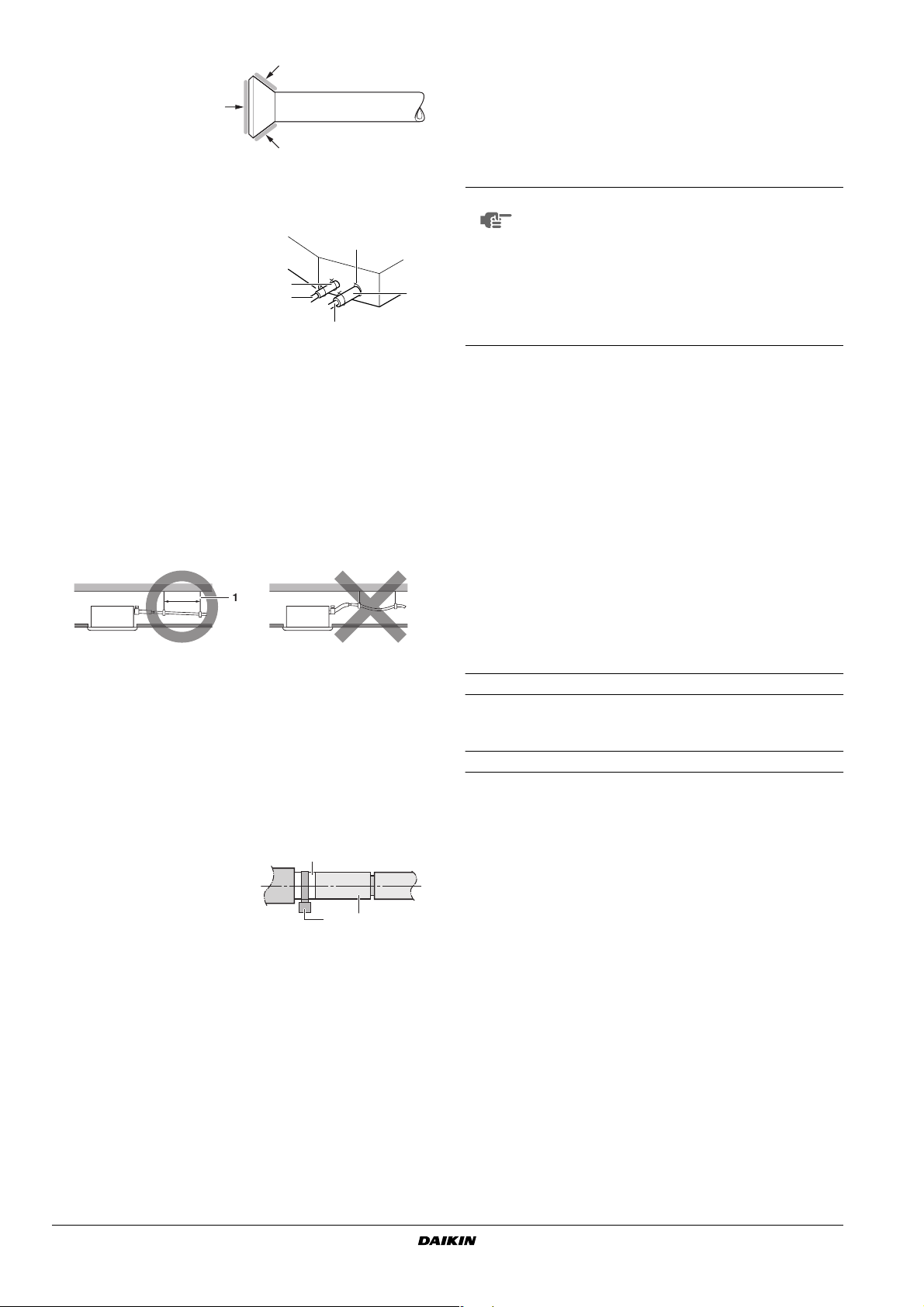
Flare shape
±0.5
90°
45°
±2
A
R0.4~0.8
■ When connecting the flare nut, coat the flare both inside and
outside with ether oil or ester oil and initially tighten by hand 3 or
4 turns before tightening firmly.
2
FXFQ20~125M7V1B
VRV System air conditioners
4PW15109-1
Installation and operation manual
3
Coat here with ether oil or
m
ester oil
■ Check the pipe connector for gas leaks, then insulate it as
shown in the figure below.
1 Liquid pipe
2 Gas pipe
3 Insulation for fitting of liquid line
(supplied with the unit)
4 Insulation for fitting of gas line
(supplied with the unit)
5 Clamps
(use 2 clamps per insulation)
3
1
5
4
2
2 Connect the drain hose to the drain outlet on the indoor unit, and
tighten it with the clamp.
Precautions
■ Install the drain raising pipes at a height of less than 550 mm.
■ Install the drain raising pipes at a right angle to the indoor unit
and no more than 300 mm from the unit.
NOTE
■ The incline of attached drain hose should be
75 mm or less so that the drain socket does not
have to stand additional force.
■ To ensure a downward slope of 1:100, install
hanging bars every 1 to 1.5 m.
■ If unifying multiple drain pipes, install the pipes as
shown in figure 9. Select converging drain pipes
whose gauge is suitable for the operating capacity
of the unit.
■ If the refrigerant gas leaks during the work, ventilate the area. A
toxic gas is emitted by the refrigerant gas being exposed to a fire.
■ Finally make sure there is no refrigerant gas leak. A toxic gas
may be released by the refrigerant gas leaking indoor and being
exposed to flames from an area heater, cooking stove, etc.
DRAIN PIPING WORK
Rig the drain piping as shown in figure and take measures against
condensation. Improperly rigged piping could lead to leaks and
eventually wet furniture and belongings.
1-1.5
1 Hanging bar
1. Install the drain pipes.
•Keep piping as short as possible and slope it downwards so that
air may not remain trapped inside the pipe.
•Keep pipe size equal to or greater than that of the connecting
pipe (Vinyl pipe of 25 mm nominal diameter and 32 mm outer
diameter).
• Insert the supplied drain hose into the drain socket, up to the
white tape.
• Tighten the clamp until the screw head is less then 4 mm from
the hose.
1 Clamp metal (supplied with
the unit)
2 Drain hose (supplied with
the unit)
3 White tape (field supply)
• Insulate the drain hose inside the building.
• If the drain hose cannot be sufficiently set on a slope, fit the hose
with drain raising piping (field supply).
How to perform piping (See figure 8)
1 Ceiling slab
2 Hanger bracket
3 Adjustable range
4 Drain raising pipe
5 Drain hose (supplied with the unit)
6 Clamp metal (supplied with the unit)
3
21
1 T-joint converging drain pipes
2. After piping work is finished, check if drainage flows
smoothly.
• Open the water inlet lid, add approximately 2 l of water gradually
and check the drainage flow.
Method of adding water. See figure 13.
1 Por table pump
2 Drain pipe
3 Service cover
4 Inspection opening
5 Service drain outlet (with rubber plug) (Use this outlet to drain
water from the drain pan)
6 Plastic watering can (Tube should be about 100 mm long.)
(Adding water through air discharge outlet)
7 Bucket (Adding water from inspection opening)
When electric wiring work is finished
Check drainage flow during COOL running, explained in chapter
"Test operation".
When electric wiring work is not finished
■ Remove the switch box lid and connect the power supply and
remote controller to the terminals.
See figure 12.
1 Switch box lid (1)
2 Power supply
3 Power supply terminal board
4 Rubber bush A
5 Clamp A
6 Switch box lid (2) with wiring diagram label
7 Tr ansmission wiring
8 Te r minal board for transmission wiring
9 Rubber bush B
10 Clamp B
11 Outside of the unit
12 Inside of the unit
13 Cable (power supply or transmission wiring)
14 Opening for the cable
15 Small sealing (supplied with the unit)
1 Connect the drain hose to the drain raising pipes, and insulate
them.
Installation and operation manual
4
FXFQ20~125M7V1B
VRV System air conditioners
4PW15109-1
•Next, press the inspection/test operation button on the
remote controller. The unit will engage the test operation mode.
Press the operation mode selector button until selecting
fan operation . Then, press the on/off button . The indoor
unit fan and drain pump will start up. Check that the water has
drained from the unit. Press to go back to the first mode.
TEST
TEST
NOTE
■ For details, refer to the chapter "Wiring example".
■ Allowable length of transmission wiring between
indoor and outdoor units, and between the indoor
unit and the remote controller is as follows:
• Outdoor unit - indoor unit: max. 1000 m
(total wiring length: 2000 m)
• Indoor unit - remote controller: max 500 m
ELECTRIC WIRING WORK
General instructions
■ All field supplied parts and materials and electric works must
conform to local codes.
■ Use copper wire only.
■ Follow the "Wiring diagram" attached to the unit body to wire the
outdoor unit, indoor units and the remote controller. For details
on hooking up the remote controller, refer to the "Installation
manual of the remote controller".
■ All wiring must be performed by an authorized electrician.
■ A circuit breaker capable of shutting down power supply to the
entire system must be installed.
Note that the operation will restart automatically if the main
power supply is turned off and then turned back on again.
■ This system consists of multiple indoor units. Mark each indoor
unit as unit A, unit B..., and be sure the terminal board wiring to
the outdoor unit and BS unit are properly matched. If wiring and
piping between the outdoor unit and an indoor unit are
mismatched, the system may cause a malfunction.
Electrical characteristics
Model Hz Volts Voltage range
FXFQ20~125 50 230 min. 198-max. 264
power supply Fan motor
Model MCA MFA KW FLA
FXFQ20•25•32•40•50 0.5 16 A 0.045 0.4
FXFQ63 0.6 16 A 0.045 0.5
FXFQ80 1.0 16 A 0.090 0.8
FXFQ100 1.1 16 A 0.090 0.9
FXFQ125 1.4 16 A 0.090 1.1
MCA: Min. circuit Amps (A)
MFA: Max. Fuse Amps (A)
KW: Fan Motor Rated Output (kW)
FLA: Full Load Amps (A)
NOTE
Specifications for field supplied fuses and wire
Model Field fuses Wire Size
FXFQ20~125 16 A H05VV-U3G Local codes
For details, refer to "Electrical data".
Power supply wiring
WIRING EXAMPLE AND HOW TO SET THE
REMOTE CONTROLLER
How to connect wiring (See figure 12)
■ Power supply wiring
Remove the switch box lid (1) and connect the wires to the
power supply terminal board inside. While doing this, pull the
wires inside through the rubber bush A and clamp the wires
along with other wires using clamp A, untightening the clip of
clamp A by pressing. After the connection, tighten clamp A as
before.
■ Unit wiring and remote controller wiring
Remove the switch box lid (2) and pull the wires inside through
the rubber bush B and connect to the terminal board for unit
transmission wiring.
■ After connection
Attach the small sealing (supplied with the unit) around the
cables to prevent infiltrating of water from the outside into the
unit. If two or more cables are used, divide the small sealing into
the required number of pieces and wrap them around all the
cables.
1 Switch box lid (1)
2 Power supply
3 Power supply terminal board
4 Rubber bush A
5 Clamp A
6 Switch box lid (2) with wiring diagram label
7 Tr ansmission wiring
8 Te r minal board for transmission wiring
9 Rubber bush B
10 Clamp B
11 Outside of the unit
12 Inside of the unit
13 Cable (power supply or transmission wiring)
14 Opening for the cable
15 Small sealing
Precautions
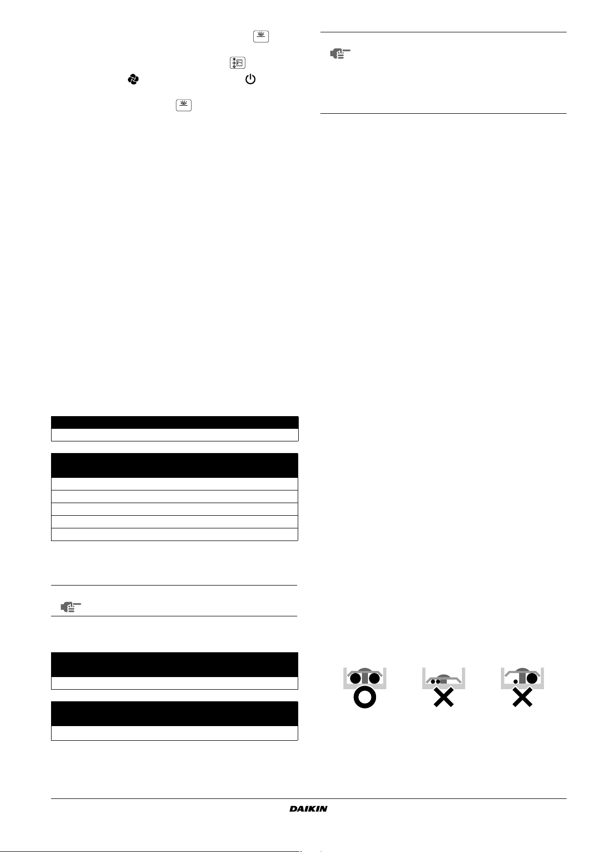
1 Observe the notes mentioned below when wiring to the power
supply terminal board.
• Do not connect wires of different gauge to the same power supply
terminal. (Looseness in the connection may cause overheating.)
• When connecting wires of the same gauge, connect them
according to the figure.
Transmission wiring
Model Wire Size
FXFQ20~125 Sheathed wire (2)
FXFQ20~125M7V1B
VRV System air conditioners
4PW15109-1
0.75-1.25 mm
2
Use the specified electric wire. Connect the wire securely to the
terminal. Lock the wire down without applying excessive force to
the terminal. (tightening torque 1.31 N•m ±10 %)
Installation and operation manual
5

2 Keep total current of crossover wiring between indoor units less
than 12 A. Branch the line outside the terminal board of the unit
in accordance with electrical equipment standards, when using
two power wiring of a gauge greater than 2 mm
2
(Ø1.6).
The branch must be sheathed in order to provide an equal or
greater degree of insulation as power supply wiring itself.
3 Do not connect wires of different gauge to the same grounding
terminal. Looseness in the connection may deteriorate the
protection.
4 Remote controller cords and wires connecting the units should
be located at least 50 mm away from power supply wiring. Not
following this guideline may result in malfunction due to electrical
noise.
5 For the remote controller wiring, refer to the "Installation manual
of the remote controller" supplied with the remote controller.
6 Never connect the power supply wiring to the terminal board for
transmission wiring. This mistake could damage the entire
system.
Precautions
1. A single switch can be used to supply power to units on the same
system. However, branch switches and branch circuit breakers must
be selected carefully.
2. For a group control remote controller, choose the remote
controller that suits the indoor unit which has the most functions.
3. Do not ground the equipment on gas pipes, water pipes,
lightning rods or crossground with telephones. Improper
grounding could result in electric shock.
FIELD SETTING
Field setting must be made from the remote controller in accordance
with the installation condition.
■ Setting can be made by changing the "Mode number", "FIRST
CODE No." and "SECOND CODE No.".
■ For setting and operation, refer to the "Field setting" in the
installation manual of the remote controller.
7 Use only specified wires and tightly connect wires to the
terminals. Be careful that wires do not place external stress on
the terminals. Keep wiring in neat order so that they do not
obstruct other equipment such as popping open the service
cover. Make sure the cover closes tight. Incomplete connections
could result in overheating, and in the worse case, electric shock
or fire.
WIRING EXAMPLE
■ Fit the power supply wiring of each unit with a switch and fuse as
shown in figure 21.
1 Power supply
2 Main switch
3 Power supply wiring
4 Tr ansmission wiring
5 Switch
6 Fuse
7 BS unit REYQ only
8 Indoor unit
9 Remote controller
Complete system example (3 systems)
■ See figures 14, 16 and 18.
1 Outdoor unit
2 Indoor unit
3 Remote controller (Optional accessories)
4 Most downstream indoor unit
5 For use with 2 remote controllers
6 BS unit
When using 1 remote controller for 1 indoor unit. (Normal
operation.) (See figure 14).
For group control or use with 2 remote controllers
When including BS unit (See figure 18).
(See figure 16).
Setting ceiling height
■ Select the SECOND CODE No. that corresponds to the ceiling
height. (SECOND CODE No. is factory set to "01" for a ceiling
height of 2.7 m or less.)
Ceiling height (m)
units 20~63 units 80~125 Mode n° 1st code n° 2nd code n°
<2.7 <3.2 N 13 (23) 0 01
>2.7 or <3.0 <3.2 or <3.6 H 13 (23) 0 02
>3.0 or <3.5 >3.6 or <4.2 S 13 (23) 0 03
The figure of ceiling height is for air discharge in 4 directions.
Setting air discharge direction
■ For changing air discharge direction (2 or 3 directions), refer to
the option handbook of the optional blocking pad kit. (SECOND
CODE No. is factory set to "01" for air discharge in 4 directions.)
Setting when installing high performance filters
■ In case of installing high performance filters, refer to the option
handbook of the high performance filters.
Setting air filter sign
■ Remote controllers are equipped with liquid crystal air filter signs
to display the time to clean the air filter.
■ Change the SECOND CODE No. Depending on the amount of
dirt or dust in the room. (SECOND CODE No. is factory set to
"01" for air filter contamination-light)
Air Filter contamination
Setting Display interval Mode n° 1st code n° 2nd code n°
Light ±2500 hrs 10 (20) 0 01
Heavy ±1250 hrs 10 (20) 0 02
■ When using wireless remote controllers it is necessary to use
address setting. Refer to the installation manual attached to the
wireless remote controller for the setting instructions.
NOTE
It is not necessary to designate indoor unit address
when using group control. The address is automatically set when the power is activated.
Installation and operation manual
6
FXFQ20~125M7V1B
VRV System air conditioners
4PW15109-1

Control by 2 Remote Controllers (Controlling 1 indoor
1
2
4 4
3
5
6
unit by 2 remote controllers)
■ When using 2 remote controllers, one must be set to "MAIN" and
the other to "SUB".
Main/sub changeover
1. Insert a wedge-head screwdriver into the recess between the upper
and lower part of the remote controller and, working from the
2 positions, pry off the upper part. (See figure 17)
(The remote controller PC board is attached to the upper part of
the remote controller.)
2. Tu rn the main/sub changeover switch on one of the two remote
controller PC boards to "S". (See figure 20)
(Leave the switch of the other remote controller set to "M".)
1 Remote controller PC board
2 Factory setting
3 Only one remote controller needs to be changed
Computerised control (forced off and on/off operation)
1. Wire specifications and how to perform wiring.
• Connect input from outside to terminals T1 and T2 of the terminal
board (remote controller to transmission wiring).
Wire specification Sheathed vinyl cord or cable (2 wire)
Gauge
Length Max. 100 m
External terminal
Contact that can ensure the minimum applicable load
0.75-1.25 mm
of 15 V DC, 10 mA
2
INSTALLATION OF THE DECORATION PANEL
Refer to the installation manual attached to the decoration panel.
After installing the decoration panel, ensure that there is no space
between the unit body and decoration panel. Otherwise air may leak
through the gap and cause dewdrop.
TEST OPERATION
Refer to the installation manual of the outdoor unit.
■ The operation lamp of the remote controller will flash when an
error occurs. Check the error code on the liquid crystal display to
identify the trouble. An explanation of error codes and the
corresponding trouble are provided on "Caution for servicing" of
the indoor unit.
See figure 19
1 Input A
2. Actuation
• The following table explains "forced off" and "on/off operations" in
response to input A.
Forced off on/off operation
Input "on" stops operation
Input "off" enables control
input off ➜ on: turns on the unit
(impossible by remote controllers)
input on ➜ off: turns off the unit
(by remote controller)
3. How to select forced off and on/off operation
•Turn the power on and then use the remote controller to select
operation.
• Set the remote controller to the field set mode. For details, refer
to the chapter "How to set in the field", in the remote controller
manual.
• When in the field set mode, select mode No. 12, then set the first
code (switch) No. to “1”. Then set second code (position) No. to
“01” for forced off and to “02” for on/off operation. (forced off at
factory set.) (See figure 22)
1 Second code No.
2 Mode No.
3 First code No.
4 Field set mode
Centralized control
■ For centralized control, it is necessary to designate the group
No. For details, refer to the manual of each optional controller for
centralized control.
1 Drain pumping device (built-in) drain water is removed from the
room during cooling
2 Air flow flap (at air outlet)
3 Air outlet
4 Remote controller
5 Suction grill
6 Air filter (inside suction grill)
MAINTENANCE
IMPORTANT
■ ONLY A QUALIFIED SERVICE PERSON IS ALLOWED TO
PERFORM MAINTENANCE.
■ BEFORE OBTAINING ACCESS TO TERMINAL DEVICES, ALL
POWER SUPPLY CIRCUITS MUST BE INTERRUPTED.
■ DO NOT USE WATER OR AIR OF 50°C OR HIGHER FOR
CLEANING AIR FILTERS AND OUTSIDE PANELS.
■ WHEN CLEANING THE HEAT EXCHANGER, BE SURE TO
REMOVE THE SWITCHBOX, FAN MOTOR AND DRAIN PUMP.
WATER OR DETERGENT MAY DETERIORATE THE
INSULATION OF ELECTRIC COMPONENTS AND RESULT IN
BURN-OUT OF THESE COMPONENTS.
FXFQ20~125M7V1B
VRV System air conditioners
4PW15109-1
Installation and operation manual
7

How to clean the air filter
Clean the air filter when the display shows " " (TIME TO CLEAN
AIR FILTER).
Increase the frequency of cleaning if the unit is installed in a room
where the air is extremely contaminated.
(As a yardstick for yourself, consider cleaning the filter once a half
year.)
If dirt becomes impossible to clean, change the air filter. (Air filter for
exchange is optional.)
1. Open the suction grill.
Push both knobs simultaneously and carefully lower the grille.
(Identical procedure for closing.)
5. Shut the air inlet grill.
Refer to item No. 1.
6. After turning power on, press the FILTER SIGN RESET button.
The "TIME TO CLEAN AIR FILTER" display disappears.
(For details, refer to the operation manual of the outdoor unit.)
NOTE
Do not remove the air filter except when cleaning.
Unnecessary handling may damage the filter.
How to clean the air outlet and outside panels
■ Clean with a soft cloth.
■ When it is difficult to remove stains, use water or neutral
detergent.
■ When the blade is extremely contaminated, remove it as below
and clean or exchange it. (Blade for exchange is optional.)
2. Remove the air filters.
Pull the air filter clips toward you, and detach the filter.
3. Clean the air filter.
Use a vacuum cleaner or wash the air filter with water.
When the air filter is very dirty, use a soft brush and neutral
detergent.
NOTE
■ Do not use gasoline, benzene, thinner, polishing
powder nor liquid insecticide. It may cause
discolouring or warping.
■ Do not let the indoor unit get wet. It may cause
electric shock or fire.
How to clean the suction grill
1. Open the suction grill.
Push both knobs simultaneously and carefully lower the grille.
(Identical procedure for closing.)
2. Detach the suction grill
Open the suction grill 45 degrees and lift it upward.
Remove water and dry in the shade.
4. Fix the air filter.
Attach the air filter to the suction grill by hanging it to the
projected portion above the suction grill.
Press the bottom of the air filter against the projections on the
bottom of the grille to snap the air filter into its place.
Installation and operation manual
8
3. Clean the suction grill
Wash it with a soft brush and neutral detergent, and dry thoroughly.
NOTE
When the suction grill is very dirty, use a typical kitchen
cleaner and let it sit for about 10 minutes. Than, wash it
with water.
4. Reattach the suction grill
See item n° 2.
5. Close the suction grill
See item n° 1.
Disposal requirements
Dismantling of the unit, treatment of the refrigerant, oil and eventual
other parts, should be done in accordance with the relevant local and
national regulations.
FXFQ20~125M7V1B
VRV System air conditioners
4PW15109-1

WIRING DIAGRAM
: FIELD WIRING BLK : BLACK
: TERMINAL BLU : BLUE
,
33H........................ FLOAT SWITCH
A1P........................ PRINTED CIRCUIT BOARD
C1R ....................... CAPACITOR (FAN MOTOR)
C3.......................... CAPACITOR
F1U........................ FUSE (250 V/5 A)
HAP ....................... LIGHT EMITTING DIODE (SERVICE MONITOR - GREEN)
M1F ....................... MOTOR (INDOOR FAN)
M1P ....................... MOTOR (DRAIN PUMP)
M1S ....................... MOTOR (SWING FLAP)
Q1F........................ THERMO SWITCH (M1F EMBEDDED)
R1T........................ THERMISTOR (AIR)
R2T,R3T ................ THERMISTOR (COIL)
RyP........................ MAGNETIC RELAY (DRAIN PUMP)
X1M,X2M............... TERMINAL STRIP
PC.......................... PHASE CONTROL CIRCUIT
T1R........................ TRANSFORMER (230 V/22 V)
Y1E........................ ELECTRONIC EXPANSION CIRCUIT
: CONNECTOR ORG : ORANGE
: WIRE CLAMP PNK : PINK
: PROTECTIVE EARTH (SCREW) RED : RED
WHT : WHITE
YLW : YELLOW
WIRED REMOTE CONTROLLER
R1T........................ THERMISTOR (AIR)
SS1........................ SELECTOR SWITCH (MAIN/SUB)
RECEIVER/DISPLAY UNIT (ATTACHED TO WIRELESS REMOTE CONTROLLER)
A2P,A3P................. PRINTED CIRCUIT BOARD
BS.......................... ON/OFF BUTTON
H1P........................ LIGHT EMITTING DIODE (SERVICE MONITOR - RED)
H2P........................ LIGHT EMITTING DIODE (SERVICE MONITOR - GREEN)
H3P........................ LIGHT EMITTING DIODE (SERVICE MONITOR - RED)
H4P........................ LIGHT EMITTING DIODE (SERVICE MONITOR - ORANGE)
SS1........................ SELECTOR SWITCH (MAIN/SUB)
SS2........................ SELECTOR SWITCH (WIRELESS ADDRESS SET)
CONNECTOR FOR OPTIONAL PARTS
X18A...................... CONNECTOR (ADAPTOR FOR ELECTRICAL APPENDICES)
X23A...................... CONNECTOR (WIRELESS REMOTE CONTROLLER)
RECEIVER/DISPLAY UNIT :
WIRED REMOTE CONTROLLER :
SWITCH BOX :
TRANSMISSION WIRING :
INPUT FROM OUTSIDE :
CENTRAL REMOTE CONTROLLER :
NOTE
1. WHEN USING THE CENTRAL REMOTE CONTROLLER, SEE MANUAL FOR CONNECTION TO THE UNIT.
2. X23A IS CONNECTED WHEN THE CENTRAL REMOTE CONTROLLER IS USED.
3. WHEN CONNECTING THE INPUT WIRES FROM OUTSIDE, FORCED OFF OR ON/OFF CONTROL OPERATION CAN BE
SELECTED BY THE REMOTE CONTROLLER. SEE INSTALLATION MANUAL FOR MORE DETAILS.
FXFQ20~125M7V1B
VRV System air conditioners
4PW15109-1
Installation and operation manual
9

Zandvoordestraat 300, B-8400 Oostende, Belgium
4PWEN15109-1
 Loading...