

Daikin FXCQ40M8, FXCQ20M8, FXCQ50M8, FXCQ63M8, FXCQ80M8 Service Manual
...
SiENBE34-703
Basic Training Manual
R-410A
Heat Pump 50Hz
Service
Manual
SiENBE34-703
Table of Contents i
R-410A
Heat Pump
50Hz
1. Introduction ........................................................................................... vi
1.1 Safety Cautions....................................................................................... vi
1.2 PREFACE ................................................................................................x
Part 1 General Information ........................................................... 1
1. Model Names of Indoor/Outdoor Units....................................................2
2. External Appearance...............................................................................3
2.1 Indoor Units ..............................................................................................3
3. Capacity Range.......................................................................................4
Part 2 Specifications .................................................................... 5
1. Specifications ..........................................................................................6
1.1 Outdoor Units ...........................................................................................6
1.2 Indoor Units ..............................................................................................8
Part 3 List of Electrical and Functional Parts............................ 33
1. List of Electrical and Functional Parts ...................................................34
1.1 Outdoor Unit...........................................................................................34
Part 4 Refrigerant Circuit ........................................................... 35
1. Refrigerant Circuit .................................................................................36
1.1 RXYSQ4 / 5 / 6P ....................................................................................36
2. Functional Parts Layout ........................................................................38
2.1 RXYSQ4 / 5 / 6P ....................................................................................38
Part 5 Function............................................................................39
1. Operation Mode ....................................................................................40
2. Basic Control.........................................................................................41
2.1 Normal Operation...................................................................................41
2.2 Compressor PI Control...........................................................................42
2.3 Electronic Expansion Valve PI Control...................................................43
2.4 Cooling Operation Fan Control...............................................................44
3. Special Control......................................................................................45
3.1 Startup Control .......................................................................................45
3.2 Oil Return Operation ..............................................................................46
3.3 Defrosting Operation ..............................................................................48
3.4 Pump-down Residual Operation ............................................................49
3.5 Restart Standby......................................................................................50
3.6 Stopping Operation ................................................................................51

SiENBE34-703
ii Table of Contents
4. Protection Control .................................................................................52
4.1 High Pressure Protection Control...........................................................52
4.2 Low Pressure Protection Control............................................................53
4.3 Discharge Pipe Protection Control .........................................................54
4.4 Inverter Protection Control .....................................................................55
5. Other Control.........................................................................................56
5.1 Demand Operation.................................................................................56
5.2 Heating Operation Prohibition ................................................................56
6. Outline of Control (Indoor Unit) .............................................................57
6.1 Drain Pump Control................................................................................57
6.2 Louver Control for Preventing Ceiling Dirt..............................................59
6.3 Thermostat Sensor in remote control.....................................................60
6.4 Freeze Prevention..................................................................................62
6.5 View of Operations of Swing Flaps ........................................................63
6.6 Electronic Expansion Valve Control .......................................................64
6.7 Hot Start Control (In Heating Operation Only)........................................64
Part 6 Test Operation ................................................................. 65
1. Test Operation ......................................................................................66
1.1 Procedure and Outline ...........................................................................66
1.2 Operation when Power is Turned On.....................................................69
2. Outdoor Unit PC Board Layout .............................................................70
3. Field Setting ..........................................................................................71
3.1 Field Setting from remote control ...........................................................71
3.2 Field Setting from Outdoor Unit..............................................................84
Part 7 Troubleshooting ............................................................. 103
1. Symptom-based Troubleshooting .......................................................105
2. Troubleshooting by Remote Control ...................................................108
2.1 The INSPECTION / TEST Button.........................................................108
2.2 Self-diagnosis by Wired Remote Control .............................................109
2.3 Self-diagnosis by Infrared Remote Control ..........................................110
2.4 Operation of the remote control’s Inspection / Test Operation Button .112
2.5 remote control Service Mode ...............................................................113
2.6 remote control Self-Diagnosis Function ...............................................115
3. Troubleshooting by Indication on the remote control ..........................122
3.1 “A0” Indoor Unit: Error of External Protection Device ...........................122
3.2 “A1” Indoor Unit: PC Board Defect.........................................................123
3.3 “A3” Indoor Unit: Malfunction of Drain Level Control System (S1L) ......124
3.4 “A6” Indoor Unit: Fan Motor (M1F) Lock, Overload...............................126
3.5 “A7” Indoor Unit: Malfunction of Swing Flap Motor (M1S).....................127
3.6 “A9” Indoor Unit: Malfunction of Moving Part of Electronic Expansion
Valve (Y1E) ..........................................................................................129
3.7 “AF” Indoor Unit: Drain Level above Limit..............................................131
3.8 “AJ” Indoor Unit: Malfunction of Capacity Determination Device ..........132
3.9 “C4” Indoor Unit: Malfunction of Thermistor (R2T) for Heat Exchanger 133
3.10 “C5” Indoor Unit: Malfunction of Thermistor (R3T) for Gas Pipes..........134
3.11 “C9” Indoor Unit: Malfunction of Thermistor (R1T) for Suction Air.........135
3.12 “CA” Indoor Unit: Malfunction of Thermistor for Discharge Air...............136
3.13 “CJ” Indoor Unit: Malfunction of Thermostat Sensor in remote control .137

SiENBE34-703
Table of Contents iii
3.14 “E1” Outdoor Unit: PC Board Defect ......................................................138
3.15 “E3” Outdoor Unit: Actuation of High Pressure Switch ..........................139
3.16 “E4” Outdoor Unit: Actuation of Low Pressure Sensor..........................141
3.17 “E5” Inverter Compressor Motor Lock ...................................................143
3.18 “E7” Malfunction of Outdoor Unit Fan Motor..........................................144
3.19 “E9” Outdoor Unit: Malfunction of Moving Part of Electronic Expansion
Valve (Y1E, Y3E) .................................................................................145
3.20 “F3” Outdoor Unit: Abnormal Discharge Pipe Temperature ..................147
3.21 “F6” Outdoor Unit: Refrigerant Overcharged .........................................148
3.22 “H9” Outdoor Unit: Malfunction of Thermistor (R1T) for Outdoor Air.....149
3.23 “J3” Outdoor Unit: Malfunction of Discharge Pipe Thermistor (R2T) ....150
3.24 “J5” Outdoor Unit: Malfunction of Thermistor (R3T, R5T) for Suction
Pipe 1, 2 ...............................................................................................151
3.25 “J6” Outdoor Unit: Malfunction of Thermistor (R6T) for Outdoor Unit Heat
Exchanger ............................................................................................152
3.26 “J7” Outdoor Unit: Malfunction of Thermistor (R7T) for Outdoor Unit Liquid
Pipe ......................................................................................................153
3.27 “J9” Outdoor Unit: Malfunction of Subcooling Heat Exchanger Gas Pipe
Thermistor (R4T) ..................................................................................154
3.28 “JA” Outdoor Unit: Malfunction of High Pressure Sensor......................155
3.29 “JC” Outdoor Unit: Malfunction of Low Pressure Sensor.......................156
3.30 “L1” Outdoor Unit: Malfunction of PC Board ..........................................157
3.31 “L4”
Outdoor Unit: Malfunction of Inverter Radiating Fin Temperature Rise
....158
3.32 “L5” Outdoor Unit: Inverter Compressor Abnormal ...............................159
3.33 “L8” Outdoor Unit: Inverter Current Abnormal .......................................160
3.34 “L9” Outdoor Unit: Inverter Start up Error..............................................161
3.35 “LC” Outdoor Unit: Malfunction of Transmission between Inverter and
Control PC Board .................................................................................162
3.36 “P1” Outdoor Unit: High Voltage of Capacitor in Main Inverter Circuit ...163
3.37 “UO” Outdoor Unit: Low Pressure Drop Due to Refrigerant Shortage or
Electronic Expansion Valve Failure......................................................164
3.38 “U2” Power Supply Insufficient or Instantaneous Failure ......................166
3.39 “U3” Check Operation not Executed......................................................168
3.40 “U4”
Malfunction of Transmission between Indoor Units and Outdoor Units
....169
3.41 “U5”
Malfunction of Transmission between remote control and Indoor Unit
.....171
3.42 “U8” M
alfunction of Transmission between Main and Sub remote controls
.....172
3.43 “U9” Malfunction of Transmission between Indoor and Outdoor Units
in the Same System .............................................................................173
3.44 “UA” Excessive Number of Indoor Units ................................................175
3.45 “UC” Address Duplication of Central remote control ..............................176
3.46 “UE” Malfunction of Transmission between Central remote control and
Indoor Unit............................................................................................177
3.47 “UF” System is not Set yet.....................................................................179
3.48 “UH” Malfunction of System, Refrigerant System Address Undefined...180
4. Troubleshooting by Indication on the Centralized remote control .......181
4.1 “UE” Malfunction of Transmission between Centralized remote control
and Indoor Unit.....................................................................................181
4.2 “M1” PC Board Defect ............................................................................182
4.3 “M8” Malfunction of Transmission between Optional Controllers for
Centralized Control...............................................................................183
4.4 “MA” Improper Combination of Optional Controllers for Centralized
Control..................................................................................................184

SiENBE34-703
iv Table of Contents
4.5 “MC” Address Duplication, Improper Setting ..........................................186
5. Troubleshooting by Indication on the Unified ON/OFF Control...........187
5.1 Operation Lamp Blinks .........................................................................187
5.2 Display “Under Host Computer Integrate Control” Blinks
(Repeats Single Blink)..........................................................................189
5.3 Display “Under Host Computer Integrate Control” Blinks
(Repeats Double Blink) ........................................................................192
Part 8 Appendix......................................................................... 197
1. Piping Diagrams..................................................................................198
1.1 Outdoor Unit.........................................................................................198
1.2 Indoor Unit............................................................................................199
2. Wiring Diagrams..................................................................................202
2.1 Outdoor Unit.........................................................................................202
2.2 Field Wiring ..........................................................................................203
2.3 Indoor Unit............................................................................................204
3. Option List ...........................................................................................218
3.1 Option List of Controllers......................................................................218
3.2 Option List of Outdoor Unit...................................................................220
4. Example of Connection .......................................................................222
5. Thermistor Resistance / Temperature Characteristics........................225
6. Pressure Sensor .................................................................................227
7. Method of Replacing the Inverter’s Power Transistors Modules.........228
Part 9 Precautions for New Refrigerant (R-410A) .................... 231
1. Precautions for New Refrigerant (R-410A) .........................................232
1.1 Outline ..................................................................................................232
1.2 Refrigerant Cylinders............................................................................234
1.3 Service Tools........................................................................................235
Part 10Removal Procedure ........................................................241
1. RXYSQ4 · 5 · 6 P7Y1B .......................................................................242
1.1 Procedure to Remove Outside Panels.................................................242
1.2 Procedure to Remove Propeller Fan and Fan Motor ...........................245
1.3 Procedure to Remove Compressor......................................................247
Index ............................................................................................. i
Drawings & Flow Charts ...............................................................iii
SiENBE34-703 Introduction
v
1. Introduction
1.1 Safety Cautions
Cautions and
Warnings
! Be sure to read the following safety cautions before conducting repair work.
! The caution items are classified into “ Warning” and “ Caution”. The “ Warning”
items are especially important since they can lead to death or serious injury if they are not
followed closely. The “ Caution” items can also lead to serious accidents under some
conditions if they are not followed. Therefore, be sure to observe all the safety caution items
described below.
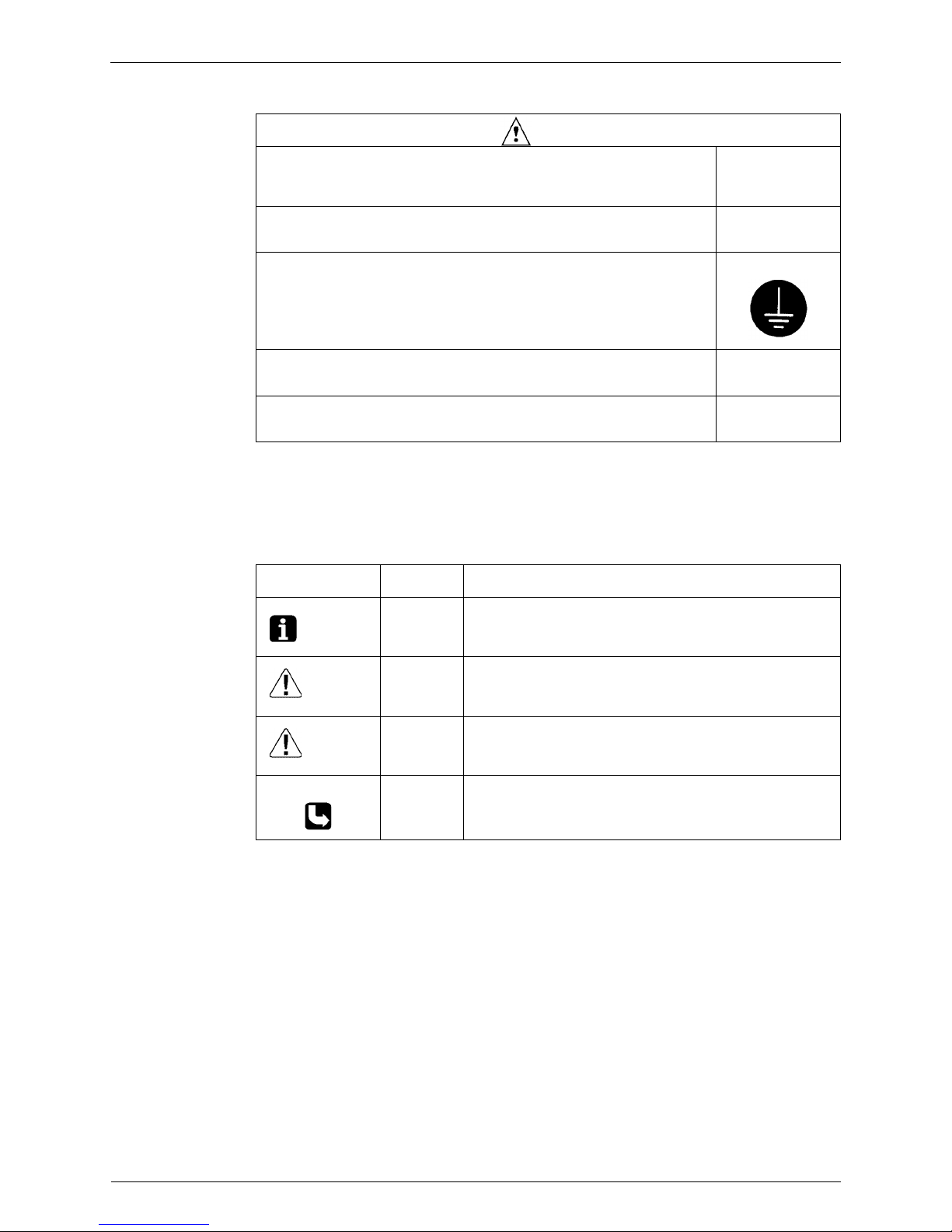
! About the pictograms
This symbol indicates an item for which caution must be exercised.
The pictogram shows the item to which attention must be paid.
This symbol indicates a prohibited action.
The prohibited item or action is shown inside or near the symbol.
This symbol indicates an action that must be taken, or an instruction.
The instruction is shown inside or near the symbol.
! After the repair work is complete, be sure to conduct a test operation to ensure that the
equipment operates normally, and explain the cautions for operating the product to the
customer
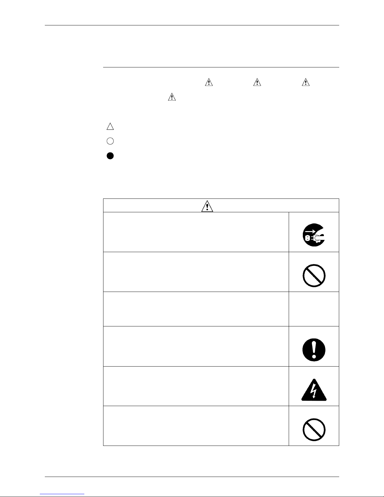
1.1.1 Caution in Repair
Warning
Be sure to disconnect the power cable plug from the plug socket before
disassembling the equipment for a repair.
Working on the equipment that is connected to a power supply can cause an
electrical shook.
If it is necessary to supply power to the equipment to conduct the repair or
inspecting the circuits, do not touch any electrically charged sections of the
equipment.
If the refrigerant gas discharges during the repair work, do not touch the
discharging refrigerant gas.
The refrigerant gas can cause frostbite.
When disconnecting the suction or discharge pipe of the compressor at the
welded section, release the refrigerant gas completely at a well-ventilated
place first.
If there is a gas remaining inside the compressor, the refrigerant gas or
refrigerating machine oil discharges when the pipe is disconnected, and it can
cause injury.
If the refrigerant gas leaks during the repair work, ventilate the area. The
refrigerant gas can generate toxic gases when it contacts flames.
The step-up capacitor supplies high-voltage electricity to the electrical
components of the outdoor unit.
Be sure to discharge the capacitor completely before conducting repair work.
A charged capacitor can cause an electrical shock.
Do not start or stop the air conditioner operation by plugging or unplugging the
power cable plug.
Plugging or unplugging the power cable plug to operate the equipment can
cause an electrical shock or fire.
Introduction SiENBE34-703
vi
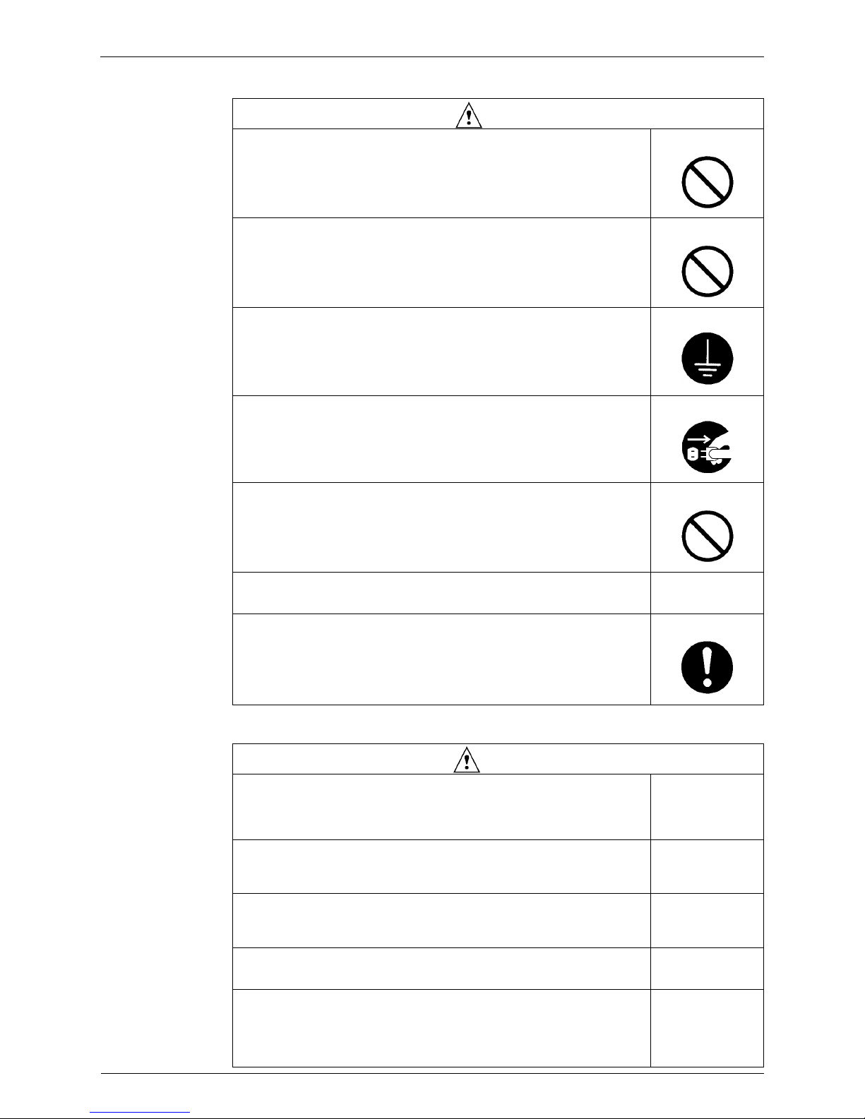
1.1.2 Cautions Regarding Products after Repair
Caution
Do not repair the electrical components with wet hands.
Working on the equipment with wet hands can cause an electrical shock.
Do not clean the air conditioner by splashing water.
Washing the unit with water can cause an electrical shock.
Be sure to provide the grounding when repairing the equipment in a humid or
wet place, to avoid electrical shocks.
Be sure to turn off the power switch and unplug the power cable when cleaning
the equipment.
The internal fan rotates at a high speed, and cause injury.
Do not tilt the unit when removing it.
The water inside the unit can spill and wet the furniture and floor.
Be sure to check that the refrigerating cycle section has cooled down
sufficiently before conducting repair work.
Working on the unit when the refrigerating cycle section is hot can cause burns.
Use the welder in a well-ventilated place.
Using the welder in an enclosed room can cause oxygen deficiency.
Warning
Be sure to use parts listed in the service parts list of the applicable model and
appropriate tools to conduct repair work. Never attempt to modify the
equipment.
The use of inappropriate parts or tools can cause an electrical shock,
excessive heat generation or fire.
When relocating the equipment, make sure that the new installation site has
sufficient strength to withstand the weight of the equipment.
If the installation site does not have sufficient strength and if the installation
work is not conducted securely, the equipment can fall and cause injury.
Be sure to install the product correctly by using the provided standard
installation frame.
Incorrect use of the installation frame and improper installation can cause the
equipment to fall, resulting in injury.
For integral units
only
Be sure to install the product securely in the installation frame mounted on a
window frame.
If the unit is not securely mounted, it can fall and cause injury.
For integral units
only
Be sure to use an exclusive power circuit for the equipment, and follow the
technical standards related to the electrical equipment, the internal wiring
regulations and the instruction manual for installation when conducting
electrical work.
Insufficient power circuit capacity and improper electrical work can cause an
electrical shock or fire.
SiENBE34-703 Introduction
vii
1.1.3 Inspection after Repair
Be sure to use the specified cable to connect between the indoor and outdoor
units. Make the connections securely and route the cable properly so that there
is no force pulling the cable at the connection terminals.
Improper connections can cause excessive heat generation or fire.
When connecting the cable between the indoor and outdoor units, make sure
that the terminal cover does not lift off or dismount because of the cable.
If the cover is not mounted properly, the terminal connection section can cause
an electrical shock, excessive heat generation or fire.
Do not damage or modify the power cable.
Damaged or modified power cable can cause an electrical shock or fire.
Placing heavy items on the power cable, and heating or pulling the power cable
can damage the cable.
Do not mix air or gas other than the specified refrigerant (R-410A) in the
refrigerant system.
If air enters the refrigerating system, an excessively high pressure results,
causing equipment damage and injury.
If the refrigerant gas leaks, be sure to locate the leak and repair it before
charging the refrigerant. After charging refrigerant, make sure that there is no
refrigerant leak.
If the leak cannot be located and the repair work must be stopped, be sure to
perform pump-down and close the service valve, to prevent the refrigerant gas
from leaking into the room. The refrigerant gas itself is harmless, but it can
generate toxic gases when it contacts flames, such as fan and other heaters,
stoves and ranges.
When replacing the coin battery in the remote control, be sure to disposed of
the old battery to prevent children from swallowing it.
If a child swallows the coin battery, see a doctor immediately.
Warning
Caution
Installation of a leakage breaker is necessary in some cases depending on the
conditions of the installation site, to prevent electrical shocks.
Do not install the equipment in a place where there is a possibility of
combustible gas leaks.
If a combustible gas leaks and remains around the unit, it can cause a fire.
Be sure to install the packing and seal on the installation frame properly.
If the packing and seal are not installed properly, water can enter the room and
wet the furniture and floor.
For integral units
only
Warning
Check to make sure that the power cable plug is not dirty or loose, then insert
the plug into a power outlet all the way.
If the plug has dust or loose connection, it can cause an electrical shock or fire.
If the power cable and lead wires have scratches or deteriorated, be sure to
replace them.
Damaged cable and wires can cause an electrical shock, excessive heat
generation or fire.
Do not use a joined power cable or extension cable, or share the same power
outlet with other electrical appliances, since it can cause an electrical shock,
excessive heat generation or fire.
Introduction SiENBE34-703
viii
1.1.4 Using Icons
Icons are used to attract the attention of the reader to specific information. The meaning of each
icon is described in the table below:
1.1.5 Using Icons List
Caution
Check to see if the parts and wires are mounted and connected properly, and
if the connections at the soldered or crimped terminals are secure.
Improper installation and connections can cause excessive heat generation,
fire or an electrical shock.
If the installation platform or frame has corroded, replace it.
Corroded installation platform or frame can cause the unit to fall, resulting in
injury.
Check the grounding, and repair it if the equipment is not properly grounded.
Improper grounding can cause an electrical shock.
Be sure to measure the insulation resistance after the repair, and make sure
that the resistance is 1 Mohm or higher.
Faulty insulation can cause an electrical shock.
Be sure to check the drainage of the indoor unit after the repair.
Faulty drainage can cause the water to enter the room and wet the furniture
and floor.
Icon Type of
Information
Description
Note:
Note A “note” provides information that is not indispensable, but may
nevertheless be valuable to the reader, such as tips and tricks.
Caution
Caution A “caution” is used when there is danger that the reader, through
incorrect manipulation, may damage equipment, loose data, get
an unexpected result or has to restart (part of) a procedure.
Warning
Warning A “warning” is used when there is danger of personal injury.
Reference A “reference” guides the reader to other places in this binder or
in this manual, where he/she will find additional information on a
specific topic.

SiENBE34-703 Introduction
ix
1.2 PREFACE
Thank you for your continued patronage of Daikin products.
This is the new service manual for Daikin's Year 2007 VRVIII-S series Heat Pump System.
Daikin offers a wide range of models to respond to building and office air conditioning needs.
We are confident that customers will be able to find the models that best suit their needs.
This service manual contains information regarding the servicing of VRVIII-S series R-410A
Heat Pump System.
June, 2007
After Sales Service Division

Introduction SiENBE34-703
x

SiENBE34-703
General Information 1
Part 1
General Information
1. Model Names of Indoor/Outdoor Units....................................................2
2. External Appearance...............................................................................3
2.1 Indoor Units ..............................................................................................3
3. Capacity Range.......................................................................................4
Model Names of Indoor/Outdoor Units SiENBE34-703
2 General Information
1. Model Names of Indoor/Outdoor Units
*Indoor Units
Note: BEV unit is required for FXUQ only.
VE :1φ, 220~240V, 50Hz, 1φ, 220V, 60Hz
V1 :1φ, 220~240V, 50Hz
V3 :1φ, 230V, 50Hz
Outdoor Units
Type Model Name
Power Supply
Ceiling Mounted
Cassette Type
(Double Flow)
FXCQ 20M8 25M8 32M8 40M8 50M8 63M8 80M8 —
125M8
V3
Ceiling Mounted
Cassette Type
(Round Flow)
FXFQ 20P7 25P7 32P7 40P7 50P7 63P7 80P7 100P7 125P7 VE
600×600 Ceiling
Mounted Cassette
Type (Mult Flow)
FXZQ20M825M832M840M850M8———— V1
Ceiling Mounted
Cassette Corner
Type
FXKQ —
25MA 32MA 40MA
—
63MA
———
VE
Slim Ceiling
Mounted Duct
Type
FXDQP
20P25P32P——————
FXDQNA
20NA 25NA 32NA 40NA 50NA 63NA — — —
FXDQM8
20M825M8——————— V3
Ceiling Mounted
Built-In Type
FXSQ 20M8 25M8 32M8 40M8 50M8 63M8 80M8
100M8 125M8
V3
Ceiling Mounted
Duct Type
FXMQ———
40MA 50MA 63MA 80MA
100MA 125MA
VE
Ceiling Suspended
Type
FXHQ — —
32MA
——
63MA
—
100MA
—
Wall Mounted
Type
FXAQ
20MA 25MA 32MA 40MA 50MA 63MA
———
Floor Standing
Type
FXLQ
20MA 25MA 32MA 40MA 50MA 63MA
———
Concealed Floor
Standing Type
FXNQ
20MA 25MA 32MA 40MA 50MA 63MA
———
Ceiling Suspended
Cassette Type
FXUQ——————
71MA
100MA 125MA
V1
Connection Unit
BEVQM(A)
——————
71MA
100MA 125MA
VE
Series Model Name
Power Supply
Inverter Heat Pump RXYSQ 4P 5P 6P Y1
Y1 :3φ, 380~415V, 50Hz

SiENBE34-703 External Appearance
General Information 3
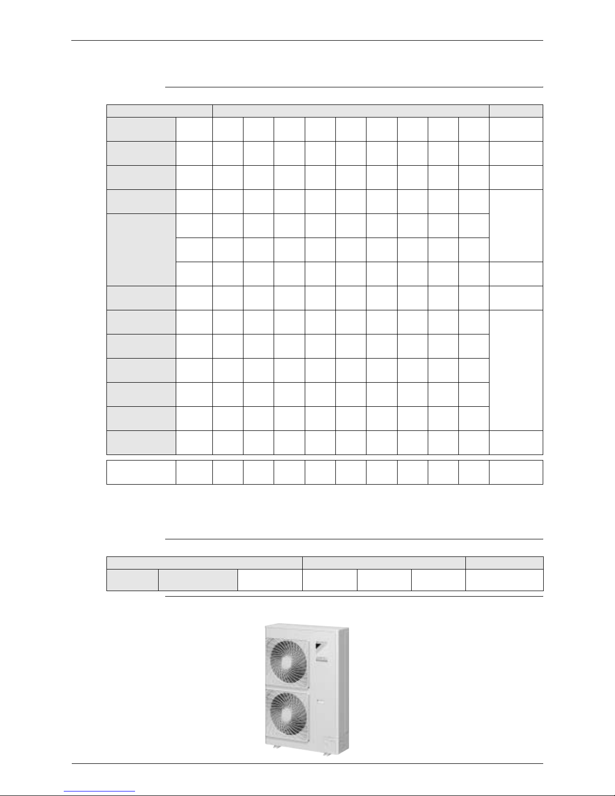
2. External Appearance
2.1 Indoor Units
Ceiling Mounted Cassette Type (Double Flow)
FXCQ20M8
FXCQ25M8
FXCQ32M8
FXCQ40M8
FXCQ50M8
FXCQ63M8
FXCQ80M8
FXCQ125M8
Ceiling Mounted Duct Type
FXMQ40MA
FXMQ50MA
FXMQ63MA
FXMQ80MA
FXMQ100MA
FXMQ125MA
Ceiling Mounted Cassette Type (Multi Flow)
FXFQ25P7
FXFQ32P7
FXFQ40P7
FXFQ50P7
FXFQ63P7
FXFQ80P7
FXFQ100P7
FXFQ125P7
Ceiling Suspended Type
FXHQ32MA
FXHQ63MA
FXHQ100MA
600×600 Ceiling Mounted
Cassette Type (Multi Flow)
FXZQ20M8
FXZQ25M8
FXZQ32M8
FXZQ40M8
FXZQ50M8
Wall Mounted Type
FXAQ20MA
FXAQ25MA
FXAQ32MA
FXAQ40MA
FXAQ50MA
FXAQ63MA
Ceiling Mounted Cassette Corner Type
FXKQ25MA
FXKQ32MA
FXKQ40MA
FXKQ63MA
Floor Standing Type
FXLQ20MA
FXLQ25MA
FXLQ32MA
FXLQ40MA
FXLQ50MA
FXLQ63MA
Slim Ceiling Mounted Duct Type
FXDQ20P, NA FXDQ20M8
FXDQ25P, NA FXDQ25M8
FXDQ32P, NA
FXDQ40NA
FXDQ50NA
FXDQ63NA
Concealed Floor Standing Type
FXNQ20MA
FXNQ25MA
FXNQ32MA
FXNQ40MA
FXNQ50MA
FXNQ63MA
Ceiling Mounted Built-In Type
FXSQ20M
FXSQ25M
FXSQ32M
FXSQ40M
FXSQ50M
FXSQ63M
FXSQ80M
FXSQ100M
FXSQ125M
Ceiling Suspended Cassette Type
(Connection Unit Series)
FXUQ71MA +
FXUQ100MA +
FXUQ125MA +
Connection Unit
BEVQ71MA
BEVQ100MA
BEVQ125MA

Capacity Range SiENBE34-703
4 General Information
3. Capacity Range
Outdoor Units
Indoor Units
Capacity Range 4HP 5HP 6HP
RXYSQ 4P 5P 6P
No of Indoor
Units to be
Connected
689
Total Capacity
Index of Indoor
Units to be
Connected
50~130 62.5~162.5 70~182
Capacity Range 0.8HP 1HP
1.25HP
1.6HP 2HP 2.5HP 3.2HP 4HP 5HP
Capacity Index 20 25 31.25 40 50 62.5 80 100 125
Ceiling Mounted
Cassette Type
(Double Flow)
FXCQ 20M8 25M8 32M8 40M8 50M8 63M8 80M8 — 125M8
Ceiling Mounted
Cassette Type
(Multi Flow)
FXFQ 20P7 25P7 32P7 40P7 50P7 63P7 80P7 100P7 125P7
600×600 Ceiling
Mounted Cassette
Type (Multi Flow)
FXZQ20M825M832M840M850M8————
Ceiling Mounted
Cassette Corner Type
FXKQ — 25MA 32MA 40MA — 63MA — — —
Slim Ceiling Mounted
Duct Type
FXDQ-P20P25P32P——————
FXDQ-NA 20NA 25NA 32NA 40NA 50NA 63NA — — —
FXDQ-M820M825M8———————
Ceiling Mounted
Built-In Type
FXSQ 20M8 25M8 32M8 40M8 50M8 63M8 80M8 100M8 125M8
Ceiling Mounted
Duct Type
FXMQ — — — 40MA 50MA 63MA 80MA 100MA 125MA
Ceiling Suspended
Type
FXHQ ——32MA——63MA—100MA—
Wall Mounted Type
FXAQ 20MA 25MA 32MA 40MA 50MA 63MA — — —
Floor Standing Type
FXLQ 20MA 25MA 32MA 40MA 50MA 63MA — — —
Concealed Floor
Standing Type
FXNQ 20MA 25MA 32MA 40MA 50MA 63MA — — —
Ceiling Suspended
Cassette Type
FXUQ ——————71MA100MA125MA

SiENBE34-703
Specifications 5
Part 2
Specifications
1. Specifications ..........................................................................................6
1.1 Outdoor Units ...........................................................................................6
1.2 Indoor Units ..............................................................................................8
Specifications SiENBE34-703
6 Specifications
1. Specifications
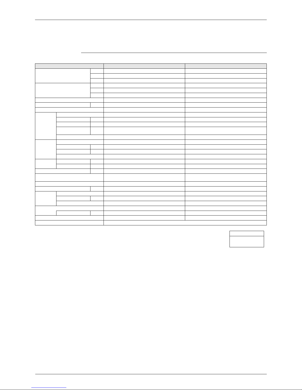
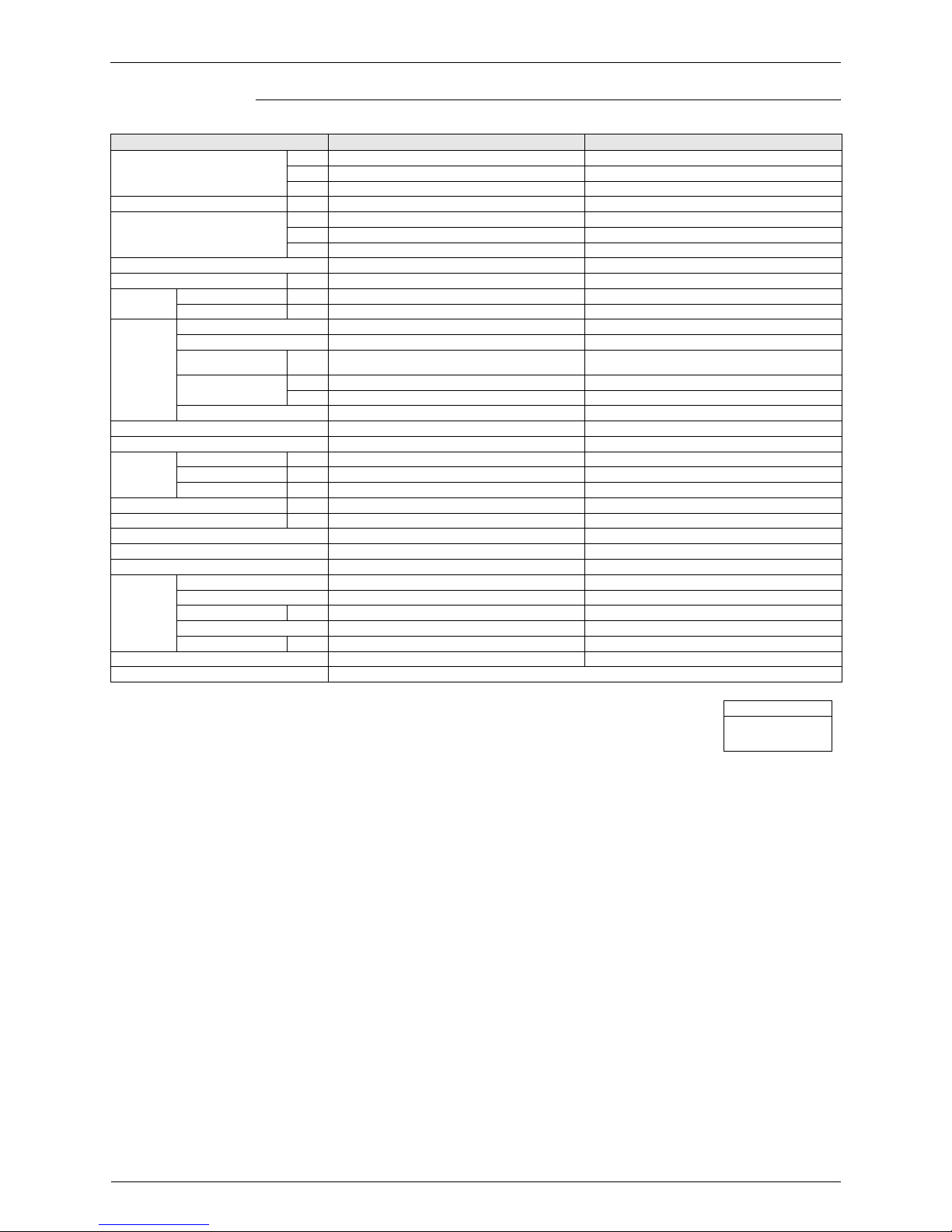
1.1 Outdoor Units
Heat Pump 50Hz <RXYSQ-P7Y1B>
Notes:
H1 Indoor temp. : 27°CDB, 19°CWB / outdoor temp. : 35°CDB / Equivalent piping length : 7.5m, level
difference : 0m.
H2 Indoor temp. : 20°CDB / outdoor temp. : 7°CDB, 6°CWB / Equivalent piping length : 7.5m, level difference
: 0m.
Model Name RXYSQ4P7Y1B RXYSQ5P7Y1B
H1 Cooling Capacity
kcal / h 9,600 12,000
Btu / h 38,200 47,800
kW 11.2 14.0
H2 Heating Capacity
kcal / h 10,800 13,800
Btu / h 42,700 54,600
kW 12.5 16.0
Casing Color Daikin White Daikin White
Dimensions: (H×W×D) mm 1,345×900×320 1,345×900×320
Heat Exchanger Cross Fin Coil Cross Fin Coil
Comp.
Type Hermetically Sealed Scroll Type Hermetically Sealed Scroll Type
Piston Displacement m³/h 19.36 19.36
Number of Revolutions r.p.m 6,480 6,480
Motor Output×Number
of Units
kW 2.5×1 3.0×1
Starting Method Direct on line Direct on line
Fan
Type Propeller Fan Propeller Fan
Motor Output W 70×270×2
Air Flow Rate (C/H) m³/min 106/102 106/105
Drive Direct Drive Direct Drive
Connecting
Pipes
Liquid Pipe mm φ9.52 (Flare Connection) φ9.52 (Flare Connection)
Gas Pipe mm φ15.9 (Flare Connection) φ15.9 (Flare Connection)
Machine Weight kg 120 120
Safety Devices
High Pressure Switch, Fan Driver Overload Protector,
Inverter Overload Protector, Fusible Plugs, Fuse
High Pressure Switch, Fan Driver Overload Protector,
Inverter Overload Protector, Fusible Plugs, Fuse
Defrost Method Reverse cycle defrosting Reverse cycle defrosting
Capacity Control % 24~100 24~100
Refrigerant
Refrigerant Name R-410A R-410A
Charge kg 4.0 4.0
Control Electronic Expansion Valve Electronic Expansion Valve
Refrigerator
Oil
DAPHNE FVC68D DAPHNE FVC68D
Charge Volume L 1.5 1.5
Standard Accessories Installation Manual, Operation Manual, Clamps Installation Manual, Operation Manual, Clamps
Drawing No. C: 3TW27631
Conversion Formula
kcal/h=kW×860
Btu/h=kW×3412
cfm=m³/min×35.3
SiENBE34-703 Specifications
Specifications 7
Notes:
H1 Indoor temp. : 27°CDB, 19°CWB / outdoor temp. : 35°CDB / Equivalent piping length : 7.5m, level
difference : 0m.
H2 Indoor temp. : 20°CDB / outdoor temp. : 7°CDB, 6°CWB / Equivalent piping length : 7.5m, level difference
: 0m.
Model Name RXYSQ6P7Y1B
H1 Cooling Capacity
kcal / h 13,300
Btu / h 52,900
kW 15.5
H2 Heating Capacity
kcal / h 15,500
Btu / h 61,400
kW 18.0
Casing Color Daikin White
Dimensions: (H×W×D) mm 1,345×900×320
Heat Exchanger Cross Fin Coil
Comp.
Type Hermetically Sealed Scroll Type
Piston Displacement m³/h 19.36
Number of Revolutions r.p.m 6,480
Motor Output×Number
of Units
kW 3.5×1
Starting Method Direct on line
Fan
Type Propeller Fan
Motor Output W 70×2
Air Flow Rate (C/H) m³/min 106/105
Drive Direct Drive
Connecting
Pipes
Liquid Pipe mm φ9.52 (Flare Connection)
Gas Pipe mm φ19.1 (Brazing Connection)
Machine Weight kg 120
Safety Devices
High Pressure Switch, Fan Driver Overload Protector,
Inverter Overload Protector, Fusible Plugs, Fuse
Defrost Method Reverse cycle defrosting
Capacity Control % 24~100
Refrigerant
Refrigerant Name R-410A
Charge kg 4.0
Control Electronic Expansion Valve
Refrigerator
Oil
DAPHNE FVC68D
Charge Volume L 1.5
Standard Accessories
Installation Manual, Operation Manual, Clamps,
Auxiliary Piping
Drawing No. C: 3TW27631
Conversion Formula
kcal/h=kW×860
Btu/h=kW×3412
cfm=m³/min×35.3
Specifications SiENBE34-703
8 Specifications
1.2 Indoor Units
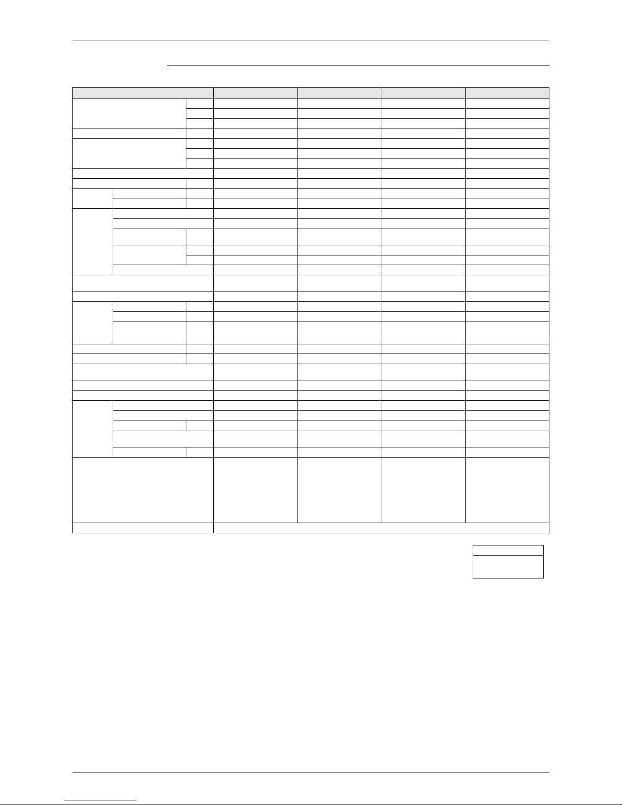
Ceiling Mounted Cassette Type (Double Flow)
Notes:
H1 Indoor temp. : 27°CDB, 19.5°CWB / outdoor temp.: 35°CDB / Equivalent piping length: 7.5m, level
difference: 0m.
H2 Indoor temp. : 27°CDB, 19.0°CWB / outdoor temp.: 35°CDB / Equivalent piping length: 7.5m, level
difference: 0m.
H3 Indoor temp. : 20°CDB / outdoor temp.: 7°CDB, 6°CWB / Equivalent piping length: 7.5m, level difference:
0m. (Heat pump only)
4 Capacities are net, including a deduction for cooling (an addition for heating) for indoor fan motor heat.
H5 Anechoic chamber conversion value, measured under JISB8616 conditions. During actual operation,
these values are normally somewhat higher as a result of ambient conditions.
Model FXCQ20M8V3 FXCQ25M8V3 FXCQ32M8V3 FXCQ40M8V3
H1 Cooling Capacity (19.5°CWB)
kcal/h
Btu/h
kW
H2 Cooling Capacity (19.0°CWB) kW
H3 Heating Capacity
kcal/h
Btu/h
kW
Casing
Dimensions: (H×W×D) mm
Coil (Cross
Fin Coil)
Rows×Stages×Fin Pitch mm
Face Area m²
Fan
Model
Type
Motor Output × Number
of Units
W
Air Flow Rate (H/L)
m³/min
cfm
Drive
Temperature Control
Sound Absorbing Thermal Insulation Material
Piping
Connections
Liquid Pipes mm
Gas Pipes mm
Drain Pipe mm
Machine Weight (Mass) kg
H5 Sound Level (H/L) (220V) dBA
Safety Devices
Refrigerant Control
Connectable outdoor unit
Decoration
Panels
(Option)
Model
Panel Color
Dimensions: (H×W×D) mm
Air Filter
Weight kg
Standard Accessories
Drawing No.
Conversion Formula
kcal/h=kW×860
Btu/h=kW×3412
cfm=m³/min×35.3

SiENBE34-703 Specifications
Specifications 9
Ceiling Mounted Cassette Type (Double Flow)
Notes:
H1 Indoor temp. : 27°CDB, 19.5°CWB / outdoor temp.: 35°CDB / Equivalent piping length: 7.5m, level
difference: 0m.
H2 Indoor temp. : 27°CDB, 19.0°CWB / outdoor temp.: 35°CDB / Equivalent piping length: 7.5m, level
difference: 0m.
H3 Indoor temp. : 20°CDB / outdoor temp.: 7°CDB, 6°CWB / Equivalent piping length: 7.5m, level difference:
0m. (Heat pump only)
4 Capacities are net, including a deduction for cooling (an addition for heating) for indoor fan motor heat.
H5 Anechoic chamber conversion value, measured under JISB8616 conditions. During actual operation,
these values are normally somewhat higher as a result of ambient conditions.
Model FXCQ50M8V3 FXCQ63M8V3 FXCQ80M8V3 FXCQ125M8V3
H1 Cooling Capacity (19.5°CWB)
kcal/h
Btu/h
kW
H2 Cooling Capacity (19.0°CWB) kW
H3 Heating Capacity
kcal/h
Btu/h
kW
Casing
Dimensions: (H×W×D) mm
Coil (Cross
Fin Coil)
Rows×Stages×Fin Pitch mm
Face Area m²
Fan
Model
Type
Motor Output × Number
of Units
W
Air Flow Rate (H/L)
m³/min
cfm
Drive
Temperature Control
Sound Absorbing Thermal Insulation Material
Piping
Connections
Liquid Pipes mm
Gas Pipes mm
Drain Pipe mm
Machine Weight (Mass) kg
H5 Sound Level (H/L) dBA
Safety Devices
Refrigerant Control
Connectable outdoor unit
Decoration
Panels
(Option)
Model
Panel Color
Dimensions: (H×W×D) mm
Air Filter
Weight kg
Standard Accessories
Drawing No.
Conversion Formula
kcal/h=kW×860
Btu/h=kW×3412
cfm=m³/min×35.3

Specifications SiENBE34-703
10 Specifications
Ceiling Mounted Cassette Type (Multi-flow)
Notes:
H1 Indoor temp. : 27°CDB, 19.5°CWB / outdoor temp.: 35°CDB / Equivalent piping length: 7.5m, level
difference: 0m.
H2 Indoor temp. : 27°CDB, 19.0°CWB / outdoor temp.: 35°CDB / Equivalent piping length: 7.5m, level
difference: 0m.
H3 Indoor temp. : 20°CDB / outdoor temp.: 7°CDB, 6°CWB / Equivalent piping length: 7.5m, level difference:
0m. (Heat pump only)
4 Capacities are net, including a deduction for cooling (an addition for heating) for indoor fan motor heat.
H5 Anechoic chamber conversion value, measured under JISB8616 conditions. During actual operation,
these values are normally somewhat higher as a result of ambient conditions.
Model FXFQ20P7VE FXFQ25P7VE FXFQ32P7VE FXFQ40P7VE
H1 Cooling Capacity (19.5°CWB)
kcal/h
Btu/h
kW
H2 Cooling Capacity (19.0°CWB) kW
H3 Heating Capacity
kcal/h
Btu/h
kW
Casing
Dimensions: (H×W×D) mm
Coil (Cross
Fin Coil)
Rows×Stages×Fin Pitch mm
Face Area m²
Fan
Model
Type
Motor Output × Number
of Units
W
Air Flow Rate (H/L)
m³/min
cfm
Drive
Temperature Control
Sound Absorbing Thermal Insulation Material
Piping
Connections
Liquid Pipes mm
Gas Pipes mm
Drain Pipe mm
Machine Weight (Mass) kg
H5 Sound Level (H/L) (220V) dBA
Safety Devices
Refrigerant Control
Connectable outdoor unit
Decoration
Panels
(Option)
Model
Panel Color
Dimensions: (H×W×D) mm
Air Filter
Weight kg
Standard Accessories
Drawing No.
Conversion Formula
kcal/h=kW×860
Btu/h=kW×3412
cfm=m³/min×35.3
SiENBE34-703 Specifications
Specifications 11
Ceiling Mounted Cassette Type (Multi-flow)
Notes:
H1 Indoor temp. : 27°CDB, 19.5°CWB / outdoor temp.: 35°CDB / Equivalent piping length: 7.5m, level
difference: 0m.
H2 Indoor temp. : 27°CDB, 19.0°CWB / outdoor temp.: 35°CDB / Equivalent piping length: 7.5m, level
difference: 0m.
H3 Indoor temp. : 20°CDB / outdoor temp.: 7°CDB, 6°CWB / Equivalent piping length: 7.5m, level difference:
0m. (Heat pump only)
4 Capacities are net, including a deduction for cooling (an addition for heating) for indoor fan motor heat.
H5 Anechoic chamber conversion value, measured under JISB8616 conditions. During actual operation,
these values are normally somewhat higher as a result of ambient conditions.
Model FXFQ50P7VE FXFQ63P7VE FXFQ80P7VE FXFQ100P7VE
H1 Cooling Capacity (19.5°CWB)
kcal/h
Btu/h
kW
H2 Cooling Capacity (19.0°CWB) kW
H3 Heating Capacity
kcal/h
Btu/h
kW
Casing
Dimensions: (H×W×D) mm
Coil (Cross
Fin Coil)
Rows×Stages×Fin Pitch mm
Face Area m²
Fan
Model
Type
Motor Output × Number
of Units
W
Air Flow Rate (H/L)
m³/min
cfm
Drive
Temperature Control
Sound Absorbing Thermal Insulation Material
Piping
Connections
Liquid Pipes mm
Gas Pipes mm
Drain Pipe mm
Machine Weight (Mass) kg
H5 Sound Level (H/L) dBA
Safety Devices
Refrigerant Control
Connectable outdoor unit
Decoration
Panels
(Option)
Model
Panel Color
Dimensions: (H×W×D) mm
Air Filter
Weight kg
Standard Accessories
Drawing No.
Conversion Formula
kcal/h=kW×860
Btu/h=kW×3412
cfm=m³/min×35.3

Specifications SiENBE34-703
12 Specifications
Notes:
H1 Indoor temp. : 27°CDB, 19.5°CWB / outdoor temp.: 35°CDB / Equivalent piping length: 7.5m, level
difference: 0m.
H2 Indoor temp. : 27°CDB, 19.0°CWB / outdoor temp.: 35°CDB / Equivalent piping length: 7.5m, level
difference: 0m.
H3 Indoor temp. : 20°CDB / outdoor temp.: 7°CDB, 6°CWB / Equivalent piping length: 7.5m, level difference:
0m. (Heat pump only)
4 Capacities are net, including a deduction for cooling (an addition for heating) for indoor fan motor heat.
H5 Anechoic chamber conversion value, measured under JISB8616 conditions. During actual operation,
these values are normally somewhat higher as a result of ambient conditions.
Model FXFQ125P7VE
H1 Cooling Capacity (19.5°CWB)
kcal/h
Btu/h
kW
H2 Cooling Capacity (19.0°CWB) kW
H3 Heating Capacity
kcal/h
Btu/h
kW
Casing
Dimensions: (H×W×D) mm
Coil (Cross
Fin Coil)
Rows×Stages×Fin Pitch mm
Face Area m²
Fan
Model
Type
Motor Output × Number
of Units
W
Air Flow Rate (H/L)
m³/min
cfm
Drive
Temperature Control
Sound Absorbing Thermal Insulation Material
Piping
Connections
Liquid Pipes mm
Gas Pipes mm
Drain Pipe mm
Machine Weight (Mass) kg
H5 Sound Level (H/L) (220V) dBA
Safety Devices
Refrigerant Control
Connectable outdoor unit
Decoration
Panels
(Option)
Model
Panel Color
Dimensions: (H×W×D) mm
Air Filter
Weight kg
Standard Accessories
Drawing No.
Conversion Formula
kcal/h=kW×860
Btu/h=kW×3412
cfm=m³/min×35.3
SiENBE34-703 Specifications
Specifications 13
600×600 Ceiling Mounted Cassette Type (Multi Flow)
Notes:
H1 Indoor temp. : 27°CDB, 19.5°CWB / outside temp.: 35°CDB / Equivalent piping length: 7.5m, level
difference: 0m.
H2 Indoor temp. : 27°CDB, 19.0°CWB / outside temp.: 35°CDB / Equivalent piping length: 7.5m, level
difference: 0m.
H3 Indoor temp. : 20°CDB / outside temp.: 7°CDB, 6°CWB / Equivalent piping length; 7.5m, level difference;
0m. (Heat pump only)
4 Capacities are net, including a deduction for cooling (an addition for heating) for indoor fan motor heat.
H5 Anechoic chamber conversion value, measured under JISB8616 conditions. During actual operation,
these values are normally somewhat higher as a result of ambient conditions.
Model FXZQ20M8V1 FXZQ25M8V1 FXZQ32M8V1
H1 Cooling Capacity (19.5°CWB)
kcal/h
Btu/h
kW
H2 Cooling Capacity (19.0°CWB) kW
H3 Heating Capacity
kcal/h
Btu/h
kW
Casing
Dimensions: (H×W×D) mm
Coil (Cross
Fin Coil)
Rows×Stages×Fin Pitch mm
Face Area m²
Fan
Model
Type
Motor Output × Number
of Units
W
Air Flow Rate (H/L)
m³/min
cfm
Drive
Temperature Control
Sound Absorbing Thermal Insulation Material
Piping
Connections
Liquid Pipes mm
Gas Pipes mm
Drain Pipe mm
Machine Weight (Mass) kg
H5 Sound Level (H/L) (230V) dBA
Safety Devices
Refrigerant Control
Connectable outside unit
Decoration
Panels
(Option)
Model
Panel Color
Dimensions: (H×W×D) mm
Air Filter
Weight kg
Standard Accessories
Drawing No.
Conversion Formula
kcal/h=kW×860
Btu/h=kW×3412
cfm=m³/min×35.3
Specifications SiENBE34-703
14 Specifications
600×600 Ceiling Mounted Cassette Type (Multi Flow)
Notes:
H1 Indoor temp. : 27°CDB, 19.5°CWB / outside temp.: 35°CDB / Equivalent piping length: 7.5m, level
difference: 0m.
H2 Indoor temp. : 27°CDB, 19.0°CWB / outside temp.: 35°CDB / Equivalent piping length: 7.5m, level
difference: 0m.
H3 Indoor temp. : 20°CDB / outside temp.: 7°CDB, 6°CWB / Equivalent piping length; 7.5m, level difference;
0m. (Heat pump only)
4 Capacities are net, including a deduction for cooling (an addition for heating) for indoor fan motor heat.
H5 Anechoic chamber conversion value, measured under JISB8616 conditions. During actual operation,
these values are normally somewhat higher as a result of ambient conditions.
Model FXZQ40M8V1 FXZQ50M8V1
H1 Cooling Capacity (19.5°CWB)
kcal/h
Btu/h
kW
H2 Cooling Capacity (19.0°CWB) kW
H3 Heating Capacity
kcal/h
Btu/h
kW
Casing
Dimensions: (H×W×D) mm
Coil (Cross
Fin Coil)
Rows×Stages×Fin Pitch mm
Face Area m²
Fan
Model
Type
Motor Output × Number
of Units
W
Air Flow Rate (H/L)
m³/min
cfm
Drive
Temperature Control
Sound Absorbing Thermal Insulation Material
Piping
Connections
Liquid Pipes mm
Gas Pipes mm
Drain Pipe mm
Machine Weight (Mass) kg
H5 Sound Level (H/L) (230V) dBA
Safety Devices
Refrigerant Control
Connectable outside unit
Decoration
Panels
(Option)
Model
Panel Color
Dimensions: (H×W×D) mm
Air Filter
Weight kg
Standard Accessories
Drawing No.
Conversion Formula
kcal/h=kW×860
Btu/h=kW×3412
cfm=m³/min×35.3
SiENBE34-703 Specifications
Specifications 15
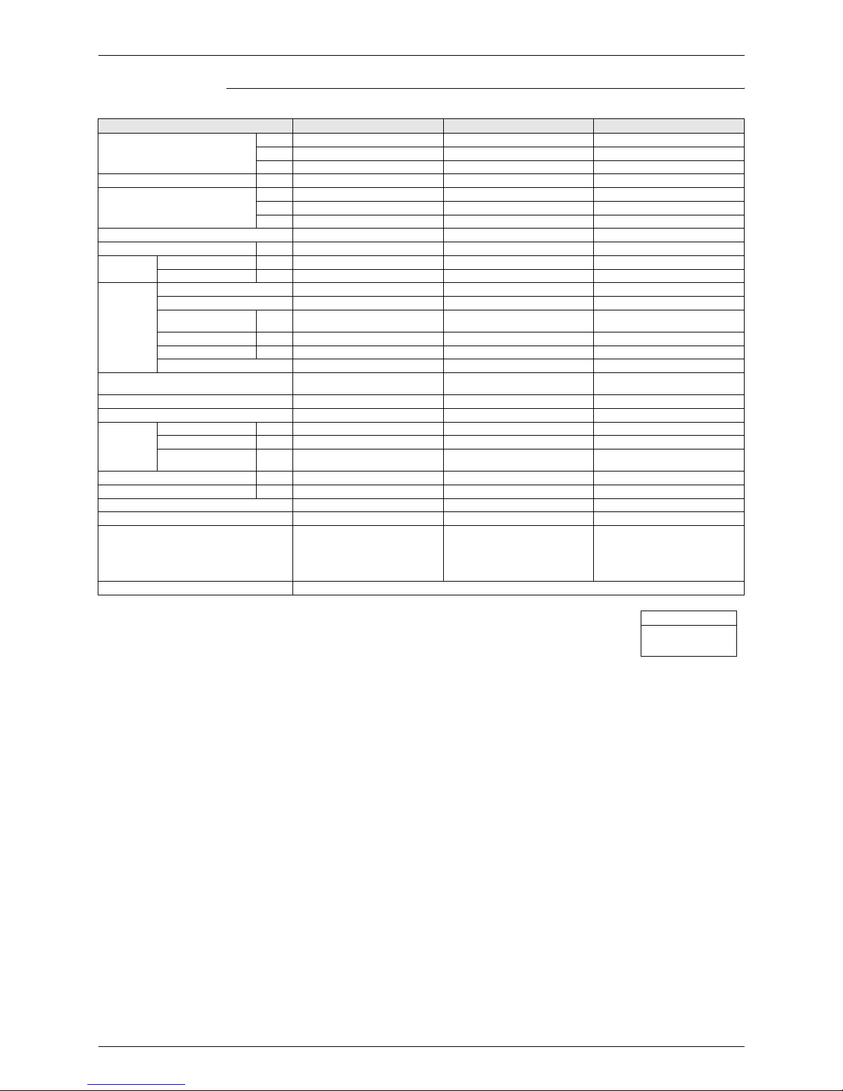
Ceiling Mounted Cassette Corner Type
Notes:
H1 Indoor temp. : 27°CDB, 19.5°CWB / outdoor temp.: 35°CDB / Equivalent piping length: 7.5m, level
difference: 0m.
H2 Indoor temp. : 27°CDB, 19.0°CWB / outdoor temp.: 35°CDB / Equivalent piping length: 7.5m, level
difference: 0m.
H3 Indoor temp. : 20°CDB / outdoor temp.: 7°CDB, 6°CWB / Equivalent piping length: 7.5m, level difference:
0m. (Heat pump only)
4 Capacities are net, including a deduction for cooling (an addition for heating) for indoor fan motor heat.
H5 Anechoic chamber conversion value, measured at a point 1m in front of the unit and 1m downward.
During actual operation, these values are normally somewhat higher as a result of ambient conditions.
Model FXKQ25MAVE FXKQ32MAVE FXKQ40MAVE FXKQ63MAVE
H1 Cooling Capacity (19.5°CWB)
kcal/h 2,500 3,200 4,000 6,300
Btu/h 9,900 12,600 16,000 24,900
kW 2.9 3.7 4.7 7.3
H2 Cooling Capacity (19.0°CWB) kW 2.8 3.6 4.5 7.1
H3 Heating Capacity
kcal/h 2,800 3,400 4,300 6,900
Btu/h 10,900 13,600 17,100 27,300
kW 3.2 4.0 5.0 8.0
Casing Galvanized Steel Plate Galvanized Steel Plate Galvanized Steel Plate Galvanized Steel Plate
Dimensions: (H×W×D) mm 215×1,110×710 215×1,110×710 215×1,110×710 215×1,310×710
Coil (Cross
Fin Coil)
Rows×Stages×Fin Pitch mm 2×11×1.75 2×11×1.75 2×11×1.75 3×11×1.75
Face Area m² 0.180 0.180 0.180 0.226
Fan
Model 3D12H1AN1V1 3D12H1AN1V1 3D12H1AP1V1 4D12H1AJ1V1
Type Sirocco Fan Sirocco Fan Sirocco Fan Sirocco Fan
Motor Output × Number
of Units
W 15×1 15×1 20×1 45×1
Air Flow Rate (H/L)
m³/min 11/9 11/9 13/10 18/15
cfm 388/318 388/318 459/353 635/530
Drive Direct Drive Direct Drive Direct Drive Direct Drive
Temperature Control
Microprocessor Thermostat
for Cooling and Heating
Microprocessor Thermostat
for Cooling and Heating
Microprocessor Thermostat
for Cooling and Heating
Microprocessor Thermostat
for Cooling and Heating
Sound Absorbing Thermal Insulation Material Polyethylene Foam Polyethylene Foam Polyethylene Foam Polyethylene Foam
Piping
Connections
Liquid Pipes mm φ6.4 (Flare Connection) φ6.4 (Flare Connection) φ6.4 (Flare Connection) φ9.5 (Flare Connection)
Gas Pipes mm φ12.7 (Flare Connection) φ12.7 (Flare Connection) φ12.7 (Flare Connection) φ15.9 (Flare Connection)
Drain Pipe mm
VP25
External Dia. 32
Internal Dia. 25
VP25
External Dia. 32
Internal Dia. 25
VP25
External Dia. 32
Internal Dia. 25
VP25
External Dia. 32
Internal Dia. 25
Machine Weight (Mass) kg 31 31 31 34
H5 Sound Level (H/L) (220V) dBA 38/33 38/33 40/34 42/37
Safety Devices
Fuse,
Thermal Fuse for Fan Motor
Fuse,
Thermal Fuse for Fan Motor
Fuse,
Thermal Fuse for Fan Motor
Fuse,
Thermal Fuse for Fan Motor
Refrigerant Control Electronic Expansion Valve Electronic E xpansion Valve Electronic Expansion Valve Electronic Expansion Valve
Connectable Outdoor Units R-410A P Series R-410A P Series R-410A P Series R-410A P Series
Decoration
Panels
(Option)
Model
BYK45FJW1 BYK45FJW1 BYK45FJW1 BYK71FJW1
Panel Color White (10Y9/0.5) White (10Y9/0.5) White (10Y9/0.5) White (10Y9/0.5)
Dimensions: (H×W×D) mm 70×1,240×800 70×1,240×800 70×1,240×800 70×1,440×800
Air Filter
Resin Net
(with Mold Resistant)
Resin Net
(with Mold Resistant)
Resin Net
(with Mold Resistant)
Resin Net
(with Mold Resistant)
Weight kg 8.5 8.5 8.5 9.5
Standard Accessories
Operation Manual,
Installation Manual, Paper
Pattern for Installation, Drain
Hose, Clamp Metal,
Insulation for Fitting, Sealing
Pads, Clamps, Screws,
Washers, Positioning Jig for
Installation, Insulation for
Hanger Bracket, Air Outlet
Blocking Pad.
Operation Manual,
Installation Manual, Paper
Pattern for Installation, Drain
Hose, Clamp Metal,
Insulation for Fitting, Sealing
Pads, Clamps, Screws,
Washers, Positioning Jig for
Installation, Insulation for
Hanger Bracket, Air Outlet
Blocking Pad.
Operation Manual,
Installation Manual, Paper
Pattern for Installation, Drain
Hose, Clamp Metal,
Insulation for Fitting, Sealing
Pads, Clamps, Screws,
Washers, Positioning Jig for
Installation, Insulation for
Hanger Bracket, Air Outlet
Blocking Pad.
Operation Manual,
Installation Manual, Paper
Pattern for Installation, Drain
Hose, Clamp Metal,
Insulation for Fitting, Sealing
Pads, Clamps, Screws,
Washers, Positioning Jig for
Installation, Insulation for
Hanger Bracket, Air Outlet
Blocking Pad.
Drawing No. 3D038813A
()()()()
Conversion Formula
kcal/h=kW×860
Btu/h=kW×3412
cfm=m³/min×35.3

Specifications SiENBE34-703
16 Specifications
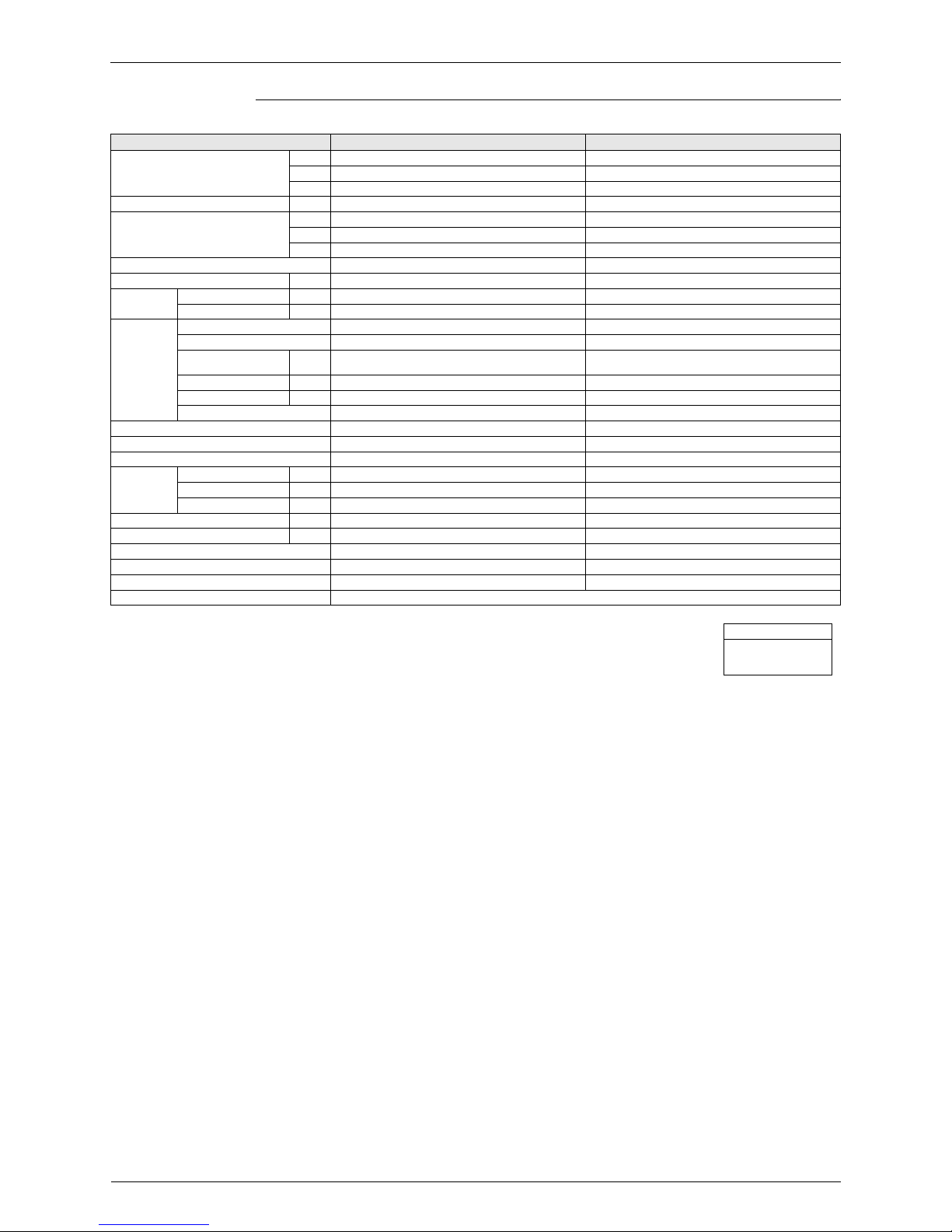
Slim Ceiling Mounted Duct Type (with Drain Pump)
Notes:
H1 Indoor temp. : 27°CDB, 19.5°CWB / outdoor temp; 35°CDB / Equivalent piping length: 7.5m, level
difference: 0m.
H2 Indoor temp. : 27°CDB, 19.0°CWB / outdoor temp; 35°CDB / Equivalent piping length: 7.5m, level
difference: 0m.
H3 Indoor temp. : 20°CDB / outdoor temp.: 7°CDB, 6°CWB / Equivalent piping length: 7.5m, level difference:
0m. (Heat pump only)
4 Capacities are net, including a deduction for cooling (an addition for heating) for indoor fan motor heat.
H5 External static pressure is changeable to set by the remote control this pressure means “High static
pressure - Standard static pressure”.
H6 The operation sound levels are the conversion values in anechoic chamber. In practice, the sound tend to
be larger than the specified values due to ambient noise or reflections.
When the place of suction is changed to the bottom suction, the sound level will increase by approx.
5dBA.
Model FXDQ20NAVE FXDQ25NAVE FXDQ32NAVE
H1 Cooling Capacity (19.5°CWB)
kcal/h 2,000 2,500 3,200
Btu/h 7,800 9,900 12,600
kW 2.3 2.9 3.7
H2 Cooling Capacity (19.0°CWB) kW 2.2 2.8 3.6
H3 Heating Capacity
kcal/h 2,200 2,800 3,400
Btu/h 8,500 10,900 13,600
kW 2.5 3.2 4.0
Casing Galvanized Steel Plate Galvanized Steel Plate Galvanized Steel Plate
Dimensions: (H×W×D) mm 200×900×620 200×900×620 200×900×620
Coil (Cross
Fin Coil)
Rows×Stages×Fin Pitch mm 2×12×1.5 2×12×1.5 2×12×1.5
Face Area m² 0.176 0.176 0.176
Fan
Model — — —
Type Sirocco Fan Sirocco Fan Sirocco Fan
Motor Output × Number
of Units
W62×162×162×1
Air Flow Rate (H/L) m³/min 9.5/7.5 9.5/7.5 10.5/8.5
External Static Pressure Pa 44-15 H5 44-15 H5 44-15 H5
Drive Direct Drive Direct Drive Direct Drive
Temperature Control
Microprocessor Thermostat
for Cooling and Heating
Microprocessor Thermostat
for Cooling and Heating
Microprocessor Thermostat
for Cooling and Heating
Sound Absorbing Thermal Insulation Material Foamed Polyethylene Foamed Polyethylene Foamed Polyethylene
Air Filter Removal / Washable / Mildew Proof Removal / Washable / Mildew Proof Removal / Washable / Mildew Proof
Piping
Connections
Liquid Pipes mm φ6.4 (Flare Connection) φ6.4 (Flare Connection) φ6.4 (Flare Connection)
Gas Pipes mm φ12.7 (Flare Connection) φ12.7 (Flare Connection) φ12.7 (Flare Connection)
Drain Pipe mm
VP20
(External Dia. 26 Internal Dia. 20)
VP20
(External Dia. 26 Internal Dia. 20)
VP20
(External Dia. 26 Internal Dia. 20)
Machine Weight (Mass) kg 26 26 26
H6 Sound Level (H/L) dBA 33/ 29 33/29 33/29
Safety Devices Fuse, Thermal Protector for Fan Motor Fuse, Thermal Protector for Fan Motor Fuse, Thermal Protector for Fan Motor
Refrigerant Control Electronic Expansion Valve Electronic Expansion Valve Electronic Expansion Valve
Standard Accessories
Operation Manual,
Installation Manual, Warranty,
Drain Hose, Sealing Pads, Clamps,
Washers, Insulation for Fitting,
Clamp Metal, Washer Fixing Plate,
Screws for Duct Flanges, Air Filter
Operation Manual,
Installation Manual, Warranty,
Drain Hose, Sealing Pads, Clamps,
Washers, Insulation for Fitting,
Clamp Metal, Washer Fixing Plate,
Screws for Duct Flanges, Air Filter
Operation Manual,
Installation Manual, Warranty,
Drain Hose, Sealing Pads, Clamps,
Washers, Insulation for Fitting,
Clamp Metal, Washer Fixing Plate,
Screws for Duct Flanges, Air Filter
Drawing No. 3D051253
Conversion Formula
kcal/h=kW×860
Btu/h=kW×3412
cfm=m³/min×35.3
SiENBE34-703 Specifications
Specifications 17
Slim Ceiling Mounted Duct Type (with Drain Pump)
Notes:
H1 Indoor temp. : 27°CDB, 19.5°CWB / outdoor temp; 35°CDB / Equivalent piping length: 7.5m, level
difference: 0m.
H2 Indoor temp. : 27°CDB, 19.0°CWB / outdoor temp; 35°CDB / Equivalent piping length: 7.5m, level
difference: 0m.
H3 Indoor temp. : 20°CDB / outdoor temp.: 7°CDB, 6°CWB / Equivalent piping length: 7.5m, level difference:
0m. (Heat pump only)
4 Capacities are net, including a deduction for cooling (an addition for heating) for indoor fan motor heat.
H5 External static pressure is changeable to set by the remote control this pressure means “High static
pressure - Standard static pressure”.
H6 The operation sound levels are the conversion values in anechoic chamber. In practice, the sound tend to
be larger than the specified values due to ambient noise or reflections.
When the place of suction is changed to the bottom suction, the sound level will increase by approx.
5dBA.
Model FXDQ40NAVE FXDQ50NAVE FXDQ63NAVE
H1 Cooling Capacity (19.5°CWB)
kcal/h 4,000 5,000 6,300
Btu/h 16,000 19,800 24,900
kW 4.7 5.8 7.3
H2 Cooling Capacity (19.0°CWB) kW 4.5 5.6 7.1
H3 Heating Capacity
kcal/h 4,300 5,400 6,900
Btu/h 17,100 21,500 27,300
kW 5.0 6.3 8.0
Casing Color Galvanized Steel Plate Galvanized Steel Plate Galvanized Steel Plate
Dimensions: (H×W×D) mm 200×900×620 200×900×620 200×1100×620
Coil (Cross
Fin Coil)
Rows×Stages×Fin Pitch mm 3×12×1.5 3×12×1.5 3×12×1.5
Face Area m² 0.176 0.176 0.227
Fan
Model — — —
Type Sirocco Fan Sirocco Fan Sirocco Fan
Motor Output × Number
of Units
W 62×1 130×1 130×1
Air Flow Rate (H/L) m³/min 10.5/8.5 12.5/10.0 16.5/13.0
External Static Pressure Pa 44-15 H5 44-15 H5 44-15 H5
Drive Direct Drive Direct Drive Direct Drive
Temperature Control
Microprocessor Thermostat
for Cooling and Heating
Microprocessor Thermostat
for Cooling and Heating
Microprocessor Thermostat
for Cooling and Heating
Sound Absorbing Thermal Insulation Material Foamed Polyethylene Foamed Polyethylene Foamed Polyethylene
Air Filter Removal / Washable / Mildew Proof Removal / Washable / Mildew Proof Removal / Washable / Mildew Proof
Piping
Connections
Liquid Pipes mm φ6.4 (Flare Connection) φ6.4 (Flare Connection) φ9.5 (Flare Connection)
Gas Pipes mm φ12.7 (Flare Connection) φ12.7 (Flare Connection) φ15.9 (Flare Connection)
Drain Pipe mm
VP20
(External Dia. 26 Internal Dia. 20)
VP20
(External Dia. 26 Internal Dia. 20)
VP20
(External Dia. 26 Internal Dia. 20)
Machine Weight (Mass) kg 27 28 31
H6 Sound Level (H/L) dBA 34/ 30 35/31 36/32
Safety Devices Fuse, Thermal Protector for Fan Motor Fuse, Thermal Protector for Fan Motor Fuse, Thermal Protector for Fan Motor
Refrigerant Control Electronic Expansion Valve Electronic Expansion Valve Electronic Expansion Valve
Standard Accessories
Operation Manual,
Installation Manual, Warranty,
Drain Hose, Sealing Pads, Clamps,
Washers, Insulation for Fitting,
Clamp Metal, Washer Fixing Plate,
Screws for Duct Flanges, Air Filter
Operation Manual,
Installation Manual, Warranty,
Drain Hose, Sealing Pads, Clamps,
Washers, Insulation for Fitting,
Clamp Metal, Washer Fixing Plate,
Screws for Duct Flanges, Air Filter
Operation Manual,
Installation Manual, Warranty,
Drain Hose, Sealing Pads, Clamps,
Washers, Insulation for Fitting,
Clamp Metal, Washer Fixing Plate,
Screws for Duct Flanges, Air Filter
Drawing No. 3D051253
Conversion Formula
kcal/h=kW×860
Btu/h=kW×3412
cfm=m³/min×35.3
Specifications SiENBE34-703
18 Specifications
Slim Ceiling Mounted Duct Type (with Drain Pump)
Notes:
H1 Indoor temp. : 27°CDB, 19.5°CWB / outdoor temp; 35°CDB / Equivalent piping length: 7.5m, level
difference: 0m.
H2 Indoor temp. : 27°CDB, 19.0°CWB / outdoor temp; 35°CDB / Equivalent piping length: 7.5m, level
difference: 0m.
H3 Indoor temp. : 20°CDB / outdoor temp.: 7°CDB, 6°CWB / Equivalent piping length; 7.5m, level difference;
0m. (Heat pump only)
4 Capacities are net, including a deduction for cooling (an addition for heating) for indoor fan motor heat.
H5 External static pressure is changeable to set by the remote control this pressure means “High static
pressure - Standard static pressure”.
H6 The operation sound levels are the conversion values in anechoic chamber. In practice, the sound tend to
be larger than the specified values due to ambient noise or reflections.
When the place of suction is changed to the bottom suction, the sound level will increase by approx.
5dBA.
Model FXDQ20M8VE FXDQ25M8VE
H1 Cooling Capacity (19.5°CWB)
kcal/h
Btu/h
kW
H2 Cooling Capacity (19.0°CWB) kW
H3 Heating Capacity
kcal/h
Btu/h
kW
Casing
Dimensions: (H×W×D) mm
Coil (Cross
Fin Coil)
Rows×Stages×Fin Pitch mm
Face Area m²
Fan
Model
Type
Motor Output × Number
of Units
W
Air Flow Rate (H/L) m³/min
External Static Pressure Pa
Drive
Temperature Control
Sound Absorbing Thermal Insulation Material
Air Filter
Piping
Connections
Liquid Pipes mm
Gas Pipes mm
Drain Pipe mm
Machine Weight (Mass) kg
H6 Sound Level (H/L) dBA
Safety Devices
Refrigerant Control
Standard Accessories
Drawing No.
Conversion Formula
kcal/h=kW×860
Btu/h=kW×3412
cfm=m³/min×35.3
SiENBE34-703 Specifications
Specifications 19
Ceiling Mounted Built-in Type
Notes:
H1 Indoor temp. : 27°CDB, 19.5°CWB / outdoor temp.: 35°CDB / Equivalent piping length: 7.5m, level
difference: 0m.
H2 Indoor temp. : 27°CDB, 19.0°CWB / outdoor temp.: 35°CDB / Equivalent piping length: 7.5m, level
difference: 0m.
H3 Indoor temp. : 20°CDB / outdoor temp.: 7°CDB, 6°CWB / Equivalent piping length: 7.5m, level difference:
0m. (Heat pump only)
H4 External static pressure is changeable to change over the connectors inside electrical box, this pressure
means
“High static pressure-Standard -Low static pressure”.
5 Capacities are net, including a deduction for cooling (an additional for heating) for indoor fan motor heat.
H6 Anechoic chamber conversion value, measured at a point 1.5m downward from the unit center. These
values are normally somewhat higher during actual operation as a result of ambient conditions.
Model FXSQ20M8V3 FXSQ25M8V3 FXSQ32M8V3
H1 Cooling Capacity (19.5°CWB)
kcal/h
Btu/h
kW
H2 Cooling Capacity (19.0°CWB) kW
H3 Heating Capacity
kcal/h
Btu/h
kW
Casing
Dimensions: (H×W×D) mm
Coil (Cross
Fin Coil)
Rows×Stages×Fin Pitch mm
Face Area m²
Fan
Model
Type
Motor Output × Number of
Units
W
Air Flow Rate (H/L) m³/min
H4 External static
pressure
Pa
Drive
Temperature Control
Sound Absorbing Thermal Insulation Material
Air Filter
Piping
Connections
Liquid Pipes mm
Gas Pipes mm
Drain Pipe mm
Machine Weight (Mass) kg
H6 Sound Level (H/L) (220V) dBA
Safety Devices
Refrigerant Control
Connectable outdoor unit
Decoration
Panel
(Option)
Model
Panel Color
Dimensions: (H×W×D) mm
Weight kg
Standard Accessories
Drawing No.
Conversion Formula
kcal/h=kW×860
Btu/h=kW×3412
cfm=m³/min×35.3
 Loading...