

Daikin FTXA20A2V1BS, CTXA15A2V1B, FTXA20A2V1BT, FTXA25A2V1B, FTXA25A2V1BW Service Manual
...
Service manual
Split Stylish R32
CTXA15A2V1B(W)(S)(T)
FTXA20A2V1B(W)(S)(T)
FTXA25A2V1B(W)(S)(T)
FTXA35A2V1B(W)(S)(T)
FTXA42A2V1B(W)(S)(T)
FTXA50A2V1B(W)(S)(T)
RXA42A2V1B
RXA50A2V1B
RXA20A2V1B
RXA25A2V1B
RXA35A2V1B
Service manual
Split Stylish R32
English

Disclaimer
Disclaimer
The present publication is drawn up by way of information only and does not constitute an offer binding upon Daikin Europe N.V.. Daikin
Europe N.V. has compiled the content of this publication to the best of its knowledge. No express or implied warranty is given for the
completeness, accuracy, reliability or fitness for particular purpose of its content and the products and services presented therein.
Specifications are subject to change without prior notice. Daikin Europe N.V. explicitly rejects any liability for any direct or indirect damage, in
the broadest sense, arising from or related to the use and/or interpretation of this publication. All content is copyrighted by Daikin Europe N.V..
Service manual
2
(C)(F)TXA15~50A2V1B(W)(S)(T) + RXA42+50A2V1B +
RXA20~35A2V1B
Split Stylish R32
ESIE18-03 – 2018.09

Table of contents
Table of contents
1 Troubleshooting 4
1.1 To display the error code on the user interface......................... 4
1.2 To reset the error code via remote controller ............................ 4
1.3 To reset the error code via outdoor unit .................................... 4
1.4 To perform a test run................................................................. 4
1.4.1 To perform a test run using the user interface............ 4
1.5 Error based troubleshooting ...................................................... 4
1.5.1 A1-00 – PCB abnormality ........................................... 4
1.5.2 A5-00 – Freeze-up protection / heating peak cut
control ......................................................................... 5
1.5.3 A6-00 – Indoor unit fan motor abnormality.................. 5
1.5.4 AH-00 – Streamer unit abnormality............................. 5
1.5.5 C4-00 – Indoor heat exchanger thermistor
abnormality ................................................................. 5
1.5.6 C9-00 – Room thermistor abnormality ........................ 5
1.5.7 CC-00 – Humidity sensor abnormality ........................ 6
1.5.8 CE-00 – Intelligent thermal sensor abnormality.......... 6
1.5.9 E1-00 – PCB defect .................................................... 6
1.5.10 E3-00 – High pressure switch abnormality ................. 6
1.5.11 E5-00 – Overheat of inverter compressor motor......... 7
1.5.12 E6-00 – Compressor startup defect ............................ 7
1.5.13 E7-00 – Fan lock abnormality ..................................... 8
1.5.14 E8-00 – Input overvoltage abnormality ....................... 8
1.5.15 EA-00 – Cooling/Heating switch abnormality .............. 8
1.5.16 F3-00 – Discharge pipe temperature stop
abnormality ................................................................. 8
1.5.17 F6-00 – Stop due to cooling high pressure ................. 9
1.5.18 F8-00 – System shutdown due to compressor
internal temperature abnormality ................................ 9
1.5.19 H0-00 – Current sensor abnormality ........................... 9
1.5.20 H3-00 – High pressure switch defect .......................... 10
1.5.21 H6-00 – Location detection sensor abnormality.......... 10
1.5.22 H8-00 – Compressor input abnormality ...................... 10
1.5.23 H9-00 – Outdoor air thermistor abnormality................ 11
1.5.24 J3-00 – Discharge pipe thermistor dislocation
abnormality ................................................................. 11
1.5.25 J6-00 – Outdoor heat exchanger thermistor
abnormality ................................................................. 11
1.5.26 L3-00 – Electrical component temperature
abnormality ................................................................. 11
1.5.27 L4-00 – Fin temperature increase abnormality ........... 11
1.5.28 L5-00 – Output over current abnormality .................... 12
1.5.29 P4-00 – Fin thermistor abnormality ............................. 12
1.5.30 U0-00 – Shortage of refrigerant .................................. 12
1.5.31 U2-00 – Main circuit voltage abnormality .................... 13
1.5.32 U4-00 – Indoor/outdoor transmission abnormality ...... 13
1.5.33 U5-00 – Transmission malfunction between indoor
unit and remote controller ........................................... 13
1.5.34 UA-00 – Indoor/outdoor combination abnormality ...... 13
1.6 Symptom based troubleshooting............................................... 15
1.6.1 Operation does not start ............................................. 15
1.6.2 Operation sometimes stops ........................................ 15
1.6.3 Operation starts but the unit does not cool/heat ......... 15
1.6.4 Operating noise and vibrations ................................... 15
1.6.5 Abnormal high pressure.............................................. 16
1.6.6 Abnormal low pressure ............................................... 16
1.6.7 Indoor fan starts operating but the compressor does
not operate.................................................................. 17
1.6.8 Operation starts and the unit stops immediately......... 17
1.6.9 Operation stops, unit cannot start for a while.............. 17
1.6.10 Unit discharges white mist .......................................... 17
1.6.11 Swing flap does not operate ....................................... 17
2 Components 18
2.1 4-way valve ............................................................................... 18
2.1.1 Checking procedures .................................................. 18
2.1.2 Repair procedures ....................................................... 19
2.2 Compressor................................................................................ 20
2.2.1 Checking procedures ................................................... 20
2.2.2 Repair procedures ....................................................... 22
2.3 Expansion valve ......................................................................... 23
2.3.1 Checking procedures ................................................... 23
2.3.2 Repair procedures ....................................................... 24
2.4 Front panel motor ....................................................................... 26
2.4.1 Checking procedures ................................................... 26
2.4.2 Repair procedures ....................................................... 26
2.5 High pressure switch .................................................................. 27
2.5.1 Checking procedures ................................................... 27
2.5.2 Repair procedures ....................................................... 27
2.6 Humidity sensor.......................................................................... 28
2.6.1 Checking procedures ................................................... 28
2.6.2 Repair procedures ....................................................... 28
2.7 Indoor unit fan motor .................................................................. 29
2.7.1 Checking procedures ................................................... 29
2.7.2 Repair procedures ....................................................... 29
2.8 Indoor unit PCB .......................................................................... 30
2.8.1 Checking procedures ................................................... 30
2.8.2 Repair procedures ....................................................... 31
2.9 Intelligent thermal sensor ........................................................... 33
2.9.1 Checking procedures ................................................... 33
2.9.2 Repair procedures ....................................................... 33
2.10 Inverter PCB ............................................................................... 34
2.10.1 Checking procedures ................................................... 34
2.10.2 Repair procedures ....................................................... 35
2.11 Main PCB ................................................................................... 35
2.11.1 Checking procedures ................................................... 35
2.11.2 Repair procedures ....................................................... 36
2.12 Outdoor unit fan motor ............................................................... 38
2.12.1 Checking procedures ................................................... 38
2.12.2 Repair procedures ....................................................... 39
2.13 Plate work................................................................................... 40
2.13.1 Outdoor unit ................................................................. 40
2.13.2 Indoor unit .................................................................... 42
2.14 Reactor ....................................................................................... 44
2.14.1 Checking procedures ................................................... 44
2.14.2 Repair procedures ....................................................... 45
2.15 Streamer unit .............................................................................. 45
2.15.1 Checking procedures ................................................... 45
2.15.2 Repair procedures ....................................................... 45
2.16 Swing flap motor......................................................................... 46
2.16.1 Main swing flap motor .................................................. 46
2.16.2 Secondary swing flap motor......................................... 47
2.17 Swing raster motor ..................................................................... 48
2.17.1 Checking procedures ................................................... 48
2.17.2 Repair procedures ....................................................... 49
2.18 Thermistors ................................................................................ 49
2.18.1 Refrigerant thermistors ................................................ 49
2.18.2 Other thermistors ......................................................... 51
2.19 Wifi control PCB ......................................................................... 51
2.19.1 Checking procedures ................................................... 51
2.19.2 Repair procedures ....................................................... 51
3 Third party components 52
3.1 Power supply.............................................................................. 52
3.1.1 Checking procedures ................................................... 52
3.1.2 Repair procedures ....................................................... 52
3.2 Refrigerant circuit ....................................................................... 53
3.2.1 Checking procedures ................................................... 53
3.2.2 Repair procedures ....................................................... 54
3.3 External factors .......................................................................... 55
3.3.1 Checking procedures ................................................... 55
3.3.2 Repair procedures ....................................................... 55
4 Maintenance 56
4.1 To clean the outdoor unit heat exchanger.................................. 56
4.2 To clean the indoor unit heat exchanger .................................... 56
(C)(F)TXA15~50A2V1B(W)(S)(T) + RXA42+50A2V1B +
RXA20~35A2V1B
Split Stylish R32
ESIE18-03 – 2018.09
Service manual
3

1 Troubleshooting
4.3 To clean the air filters ................................................................ 56
5 Technical data 57
5.1 Detailed information setting mode............................................. 57
5.1.1 Detailed information setting mode: Indoor unit ........... 57
5.1.2 Detailed information setting mode: Outdoor unit......... 57
5.1.3 Detailed information setting mode: Remote controller 57
5.2 Wiring diagram .......................................................................... 58
5.2.1 Wiring diagram: Indoor unit......................................... 58
5.2.2 Wiring diagram: Outdoor unit ...................................... 59
5.3 Piping diagram .......................................................................... 61
5.3.1 Piping diagram: Indoor unit......................................... 61
5.3.2 Piping diagram: Outdoor unit ...................................... 62
5.4 Component overview................................................................. 64
5.4.1 Component overview: Indoor unit ............................... 64
5.4.2 Component overview: Outdoor unit ............................ 66
5.5 Field information report ............................................................. 68
5.6 Field settings ............................................................................. 71
5.6.1 To control heating only mode...................................... 71
5.6.2 To adjust target set temperature in heating operation 71
5.6.3 To control the indoor unit fan during thermostat off .... 71
5.6.4 To change auto restart ON to OFF ............................. 71
5.6.5 To control cooling mode only...................................... 71
5.7 Service tools.............................................................................. 72
1 Troubleshooting
1.1 To display the error code on the user interface
Prerequisite: Test run should be performed in accordance with the
operation manual of the indoor unit to make sure that all functions
and parts are working properly.
1 In cooling mode, select the lowest programmable temperature.
In heating mode, select the highest programmable temperature.
Test run can be disabled if necessary.
2 When the test run is finished, set the temperature to a normal
level. In cooling mode: 26~28°C, in heating mode: 20~24°C.
3 The system stops operating 3minutes after the unit is turned
OFF.
INFORMATION
▪ Even if the unit is turned OFF, it consumes electricity.
▪ When the power turns back on after a power break, the
previously selected mode will be resumed.
1.4.1 To perform a test run using the user interface
1 Press to switch the system on.
2 Press , and simultaneously.
3 Press , select and press .
Result: Test run operation will stop automatically after about
30minutes.
4 To stop operation sooner, press .
1.5 Error based troubleshooting
1 Hold for about 5seconds.
Result: blinks in the temperature display section.
2 Press repeatedly until a continuous beep is heard.
Result: The code is now displayed on the display.
INFORMATION
▪ A short beep and 2 consecutive beeps indicate non-
corresponding codes.
▪ To cancel the code display, hold the cancel
button for 5seconds. The code will also disappear from
the display if the button is NOT pressed within
1minute.
1.2 To reset the error code via remote controller
Prerequisite: Problem is solved.
1 Press the ON/OFF button of the remote controller to reset the
error.
1.3 To reset the error code via outdoor unit
Prerequisite: Problem is solved.
1 Perform a power reset to reset the error code.
1.4 To perform a test run
Prerequisite: Power supply MUST be in the specified range.
Prerequisite: Test run may be performed in cooling or heating
mode.
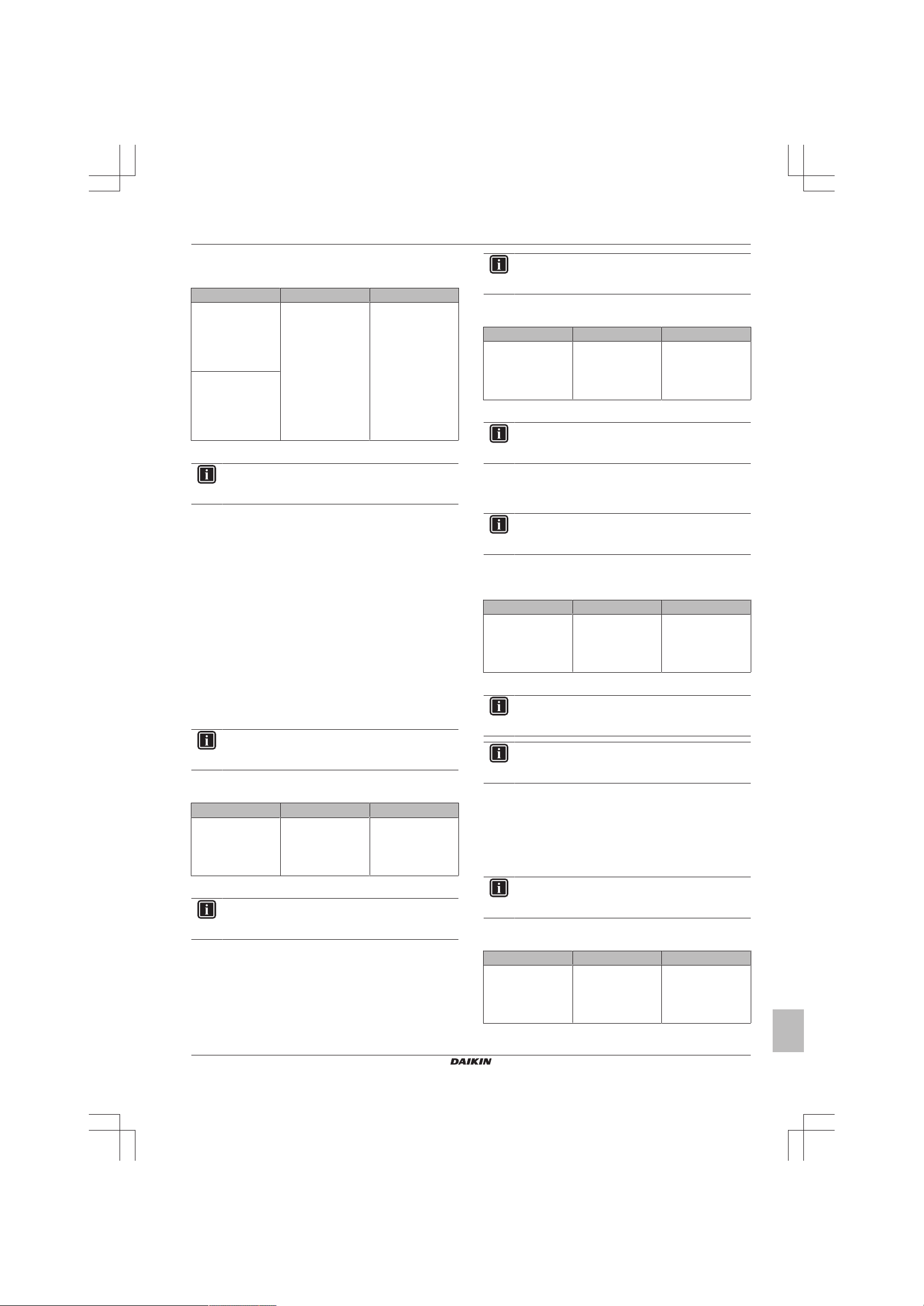
1.5.1 A1-00 – PCB abnormality
Trigger Effect Reset
The system CANNOT
set the internal
settings.
To solve the error code
INFORMATION
It is recommended to perform the checks in the listed
order.
1 Check for improper combination of the indoor unit and the
outdoor unit. See the combination table in the Databook for
more information.
2 Perform a check of the power supply, connections, wiring,…
between the outdoor unit and the indoor unit. See "3.1Power
supply"on page52.
Possible cause: Faulty wiring between the outdoor unit and
the indoor unit.
3 Check if the power supply is conform with the regulations. See
"3.1Power supply"on page52.
Possible cause:
▪ Faulty or disturbance of the power supply (imbalance
>10%),
▪ Power drop,
▪ Short circuit.
4 Perform a check of the indoor unit PCB. See "2.8Indoor unit
PCB"on page30.
Possible cause: Faulty indoor unit PCB.
INFORMATION
If all procedures listed above have been performed and the
problem is still present, contact the helpdesk.
Unit will stop
operating.
Power reset via
outdoor unit.
Service manual
4
(C)(F)TXA15~50A2V1B(W)(S)(T) + RXA42+50A2V1B +
RXA20~35A2V1B
Split Stylish R32
ESIE18-03 – 2018.09
1 Troubleshooting
1.5.2 A5-00 – Freeze-up protection / heating peak cut control
Trigger Effect Reset
During cooling
operation, indoor heat
exchanger
temperature is below
0°C (freeze‑up
protection control).
During heating
operation, indoor heat
exchanger
temperature is above
65°C (heating
peak‑cut control).
To solve the error code
INFORMATION
It is recommended to perform the checks in the listed
order.
1 Check for objects near the indoor unit that may block the
airflow. See "3.3External factors"on page55.
Possible cause: Airflow of the indoor unit is blocked.
2 Clean the air filter. See "4Maintenance"on page56.
Possible cause: Faulty or dirty air filter.
3 Clean the indoor unit heat exchanger. See "4Maintenance"on
page56.
Possible cause: Dirty indoor unit heat exchanger.
4 Perform a check of the indoor unit heat exchanger thermistor.
See "2.18Thermistors"on page49.
Possible cause: Faulty indoor unit heat exchanger
thermistor.
5 Perform a check of the indoor unit PCB. See "2.8Indoor unit
PCB"on page30.
Possible cause: Faulty indoor unit PCB.
INFORMATION
If all procedures listed above have been performed and the
problem is still present, contact the helpdesk.
Unit will stop
operating.
Automatic reset when
temperature is within
range.
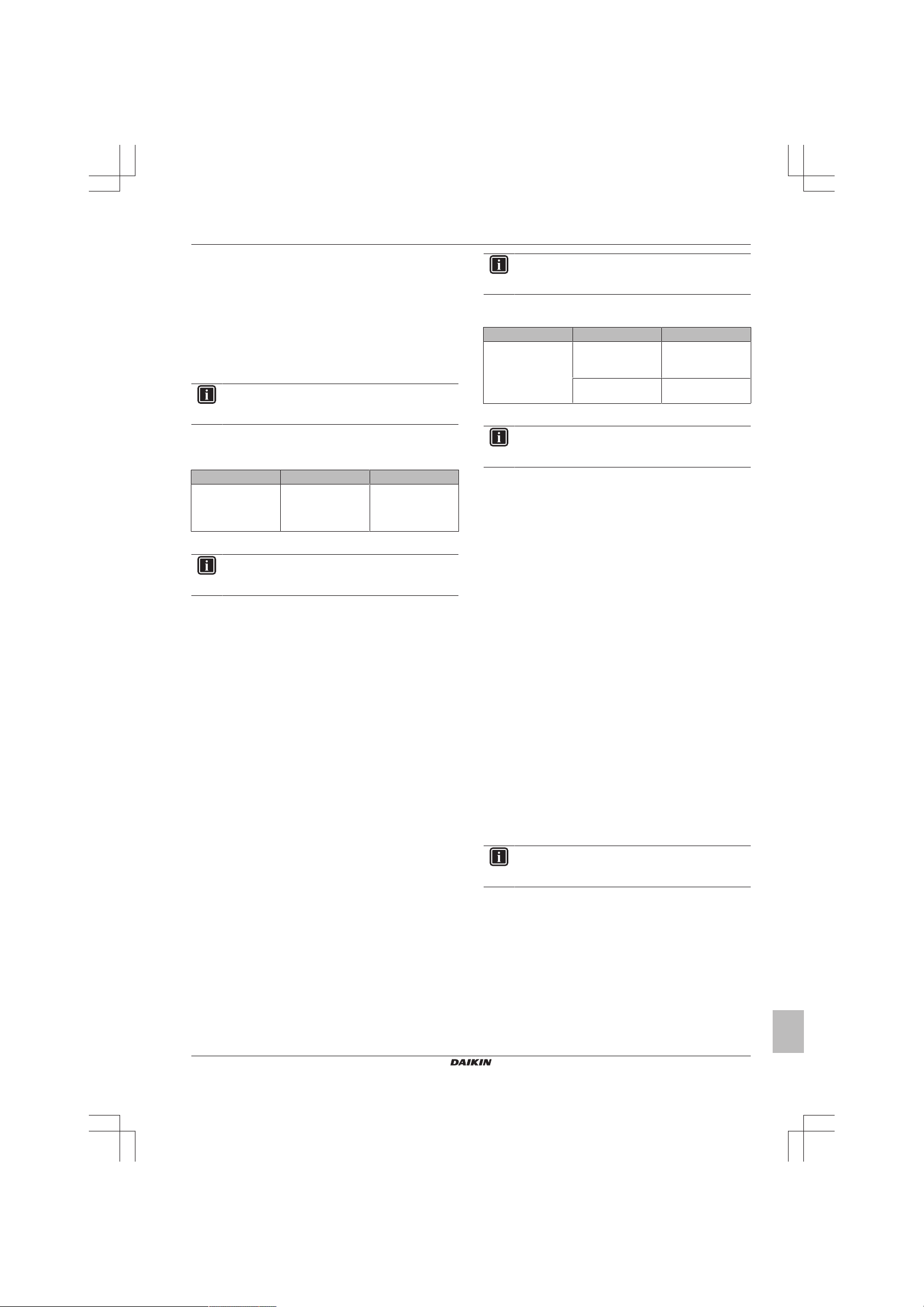
1.5.3 A6-00 – Indoor unit fan motor abnormality
Trigger Effect Reset
The rotation speed of
the fan motor is NOT
detected while the
output voltage to the
fan is at its maximum.
To solve the error code
INFORMATION
It is recommended to perform the checks in the listed
order.
1 Perform a check of the indoor unit PCB. See "2.8Indoor unit
PCB"on page30.
Possible cause: Faulty indoor unit PCB.
2 Perform a check of the indoor unit fan motor. See "2.7Indoor
unit fan motor"on page29.
Possible cause: Faulty indoor unit fan motor.
Unit will stop
operating.
Power reset via the
outdoor unit.
INFORMATION
If all procedures listed above have been performed and the
problem is still present, contact the helpdesk.
1.5.4 AH-00 – Streamer unit abnormality
Trigger Effect Reset
Streamer unit starts
electric discharge
when operation starts
after approximately
90 to 180seconds.
To solve the error code
INFORMATION
It is recommended to perform the checks in the listed
order.
1 Perform a check of the streamer unit. See "2.15 Streamer
unit"on page45.
Possible cause: Faulty streamer unit.
INFORMATION
If all procedures listed above have been performed and the
problem is still present, contact the helpdesk.
Unit will NOT stop
operating.
Manual reset via user
interface.
1.5.5 C4-00 – Indoor heat exchanger thermistor abnormality
Trigger Effect Reset
Refrigerant liquid
thermistor detects an
open or short circuit
during compressor
operation.
To solve the error code
INFORMATION
It is recommended to perform the checks in the listed
order.
INFORMATION
In case of preferential kWh rate, the indoor unit also needs
a power reset.
1 Perform a check of the refrigerant liquid thermistor. See
"2.18Thermistors"on page49.
Possible cause: Faulty refrigerant liquid thermistor.
2 Perform a check of the indoor unit PCB. See "2.8Indoor unit
PCB"on page30.
Possible cause: Faulty indoor unit PCB.
INFORMATION
If all procedures listed above have been performed and the
problem is still present, contact the helpdesk.
Unit will stop
operating.
Power reset via
outdoor unit.
1.5.6 C9-00 – Room thermistor abnormality
Trigger Effect Reset
Resistance value is
out of range.
Temperature
measured <–43.6°C
or >90°C.
Unit will stop
operating.
Automatic reset when
resistance is within
range.
(C)(F)TXA15~50A2V1B(W)(S)(T) + RXA42+50A2V1B +
RXA20~35A2V1B
Split Stylish R32
ESIE18-03 – 2018.09
Service manual
5

1 Troubleshooting
To solve the error code
INFORMATION
It is recommended to perform the checks in the listed
order.
1 Perform a check of the room thermistor. See
"2.18Thermistors"on page49.
Possible cause: Faulty room thermistor.
2 Perform a check of the indoor unit PCB. See "2.8Indoor unit
PCB"on page30.
Possible cause: Faulty indoor unit PCB.
INFORMATION
If all procedures listed above have been performed and the
problem is still present, contact the helpdesk.
1.5.7 CC-00 – Humidity sensor abnormality
Trigger Effect Reset
▪ Disconnected
sensor
▪ Broken sensor
▪ Communication
error
To solve the error code
INFORMATION
It is recommended to perform the checks in the listed
order.
1 Perform a check of the humidity sensor. See "2.6 Humidity
sensor"on page28.
Possible cause: Faulty humidity sensor.
INFORMATION
If all procedures listed above have been performed and the
problem is still present, contact the helpdesk.
Unit will stop
operating.
Manual reset via user
interface.
1.5.8 CE-00 – Intelligent thermal sensor abnormality
Trigger Effect Reset
▪ Disconnected
sensor
▪ Broken sensor
▪ Communication
error
To solve the error code
INFORMATION
It is recommended to perform the checks in the listed
order.
1 Perform a check of the intelligent thermal sensor. See
"2.9Intelligent thermal sensor"on page33.
Possible cause: Faulty intelligent thermal sensor.
INFORMATION
If all procedures listed above have been performed and the
problem is still present, contact the helpdesk.
Unit will stop
operating.
Manual reset via user
interface.
1.5.9 E1-00 – PCB defect
Trigger Effect Reset
Main PCB detects
that EEPROM is
abnormal.
To solve the error code
INFORMATION
It is recommended to perform the checks in the listed
order.
INFORMATION
In case of preferential kWh rate, the indoor unit also needs
a power reset.
1 Perform a check of the main PCB. See "2.11 Main PCB"on
page35.
Possible cause: Faulty main PCB.
2 Check if the power supply is conform with the regulations. See
"3.1Power supply"on page52.
Possible cause:
▪ Faulty or disturbance of the power supply (imbalance
>10%),
▪ Power drop,
▪ Short circuit.
3 Perform a check of the outdoor unit fan motor. See
"2.12Outdoor unit fan motor"on page38.
Possible cause: Faulty outdoor unit fan motor.
INFORMATION
If all procedures listed above have been performed and the
problem is still present, contact the helpdesk.
Unit will stop
operating.
Manual reset via user
interface.
Power reset via
outdoor unit.
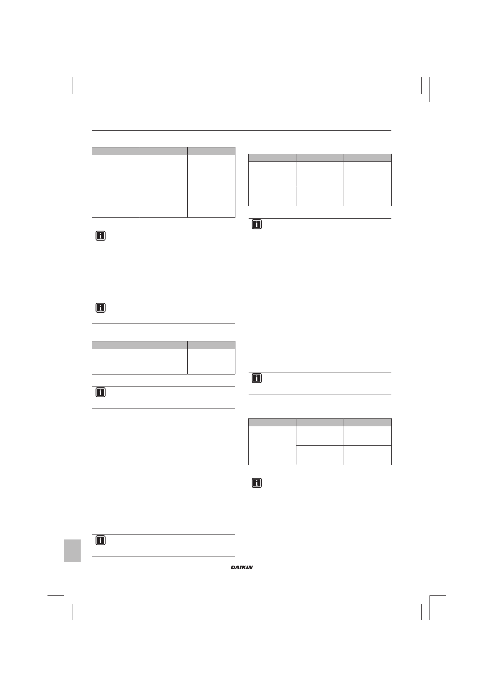
1.5.10 E3-00 – High pressure switch abnormality
Trigger Effect Reset
High pressure switch
opens due to
measured pressure
>41.7bar.
High pressure control
(measured pressure
>38bar) occurs 16
times within
300minutes.
To solve the error code
INFORMATION
It is recommended to perform the checks in the listed
order.
1 Perform a check of the high pressure switch. See "2.5 High
pressure switch"on page27.
Possible cause: Faulty high pressure switch.
2 Perform a check of the main PCB. See "2.11 Main PCB"on
page35.
Possible cause: Faulty main PCB.
3 Perform a check of the refrigerant circuit. See "3.2 Refrigerant
circuit"on page53.
Unit will stop
operating.
Manual reset via user
interface.
Service manual
6
(C)(F)TXA15~50A2V1B(W)(S)(T) + RXA42+50A2V1B +
RXA20~35A2V1B
Split Stylish R32
ESIE18-03 – 2018.09
1 Troubleshooting
Possible cause:
▪ Stop valve is closed,
▪ Clogged refrigerant circuit,
▪ Refrigerant circuit NOT charged correctly,
▪ Humidity in the refrigerant circuit,
▪ Non-condensables in the refrigerant circuit,
▪ Leaking refrigerant circuit.
4 Perform a check of the outdoor unit fan motor. See
"2.12Outdoor unit fan motor"on page38.
Possible cause: Faulty outdoor unit fan motor.
INFORMATION
If all procedures listed above have been performed and the
problem is still present, contact the helpdesk.
1.5.11 E5-00 – Overheat of inverter compressor motor
Trigger Effect Reset
Compressor overload
is detected.
To solve the error code
INFORMATION
It is recommended to perform the checks in the listed
order.
1 Perform a check of the discharge pipe thermistor. See
"2.18Thermistors"on page49.
Possible cause: Faulty discharge pipe thermistor.
2 Perform a check of the outdoor unit fan motor. See
"2.12Outdoor unit fan motor"on page38.
Possible cause: Faulty outdoor unit fan motor.
3 Perform a check of the compressor. See "2.2Compressor" on
page20.
Possible cause: Faulty compressor.
4 Perform a check of the expansion valve. See "2.3 Expansion
valve"on page23.
Possible cause: Faulty expansion valve.
5 Perform a check of the 4‑way valve. See "2.14-way valve"on
page18.
Possible cause: Faulty 4‑way valve.
6 Perform a check of the main PCB. See "2.11 Main PCB"on
page35.
Possible cause: Faulty main PCB.
7 Perform a check of the inverter PCB. See "2.10 Inverter
PCB"on page34.
Possible cause: Faulty power module = inverter PCB.
8 Perform a check of the refrigerant circuit. See "3.2 Refrigerant
circuit"on page53.
Possible cause:
▪ Stop valve is closed,
▪ Clogged refrigerant circuit,
▪ Refrigerant circuit NOT charged correctly,
▪ Humidity in the refrigerant circuit,
▪ Non-condensables in the refrigerant circuit,
▪ Leaking refrigerant circuit.
Unit will NOT stop
operating.
Automatic reset if the
unit runs without
warning for
60seconds.
INFORMATION
If all procedures listed above have been performed and the
problem is still present, contact the helpdesk.
1.5.12 E6-00 – Compressor startup defect
Trigger Effect Reset
The motor rotor does
NOT rotate when the
compressor is
energized.
To solve the error code
INFORMATION
It is recommended to perform the checks in the listed
order.
1 Perform a check of the discharge pipe thermistor. See
"2.18Thermistors"on page49.
Possible cause: Faulty discharge pipe thermistor.
2 Perform a check of the refrigerant circuit. See "3.2 Refrigerant
circuit"on page53.
Possible cause:
▪ Stop valve is closed,
▪ Clogged refrigerant circuit,
▪ Refrigerant circuit NOT charged correctly,
▪ Humidity in the refrigerant circuit,
▪ Non-condensables in the refrigerant circuit,
▪ Leaking refrigerant circuit.
3 Perform a check of the compressor. See "2.2Compressor" on
page20.
Possible cause: Faulty compressor.
4 Perform a check of the main PCB. See "2.11 Main PCB"on
page35.
Possible cause: Faulty main PCB.
5 Perform a check of the inverter PCB. See "2.10 Inverter
PCB"on page34.
Possible cause: Faulty power module = inverter PCB.
6 Perform a check of the 4‑way valve. See "2.14-way valve"on
page18.
Possible cause: Faulty 4‑way valve.
7 Perform a check of the expansion valve. See "2.3 Expansion
valve"on page23.
Possible cause: Faulty expansion valve.
INFORMATION
If all procedures listed above have been performed and the
problem is still present, contact the helpdesk.
Unit will NOT stop
operating.
Unit will stop
operating
Automatic reset after
a continuous run for
10minutes.
Manual reset via user
interface.
(C)(F)TXA15~50A2V1B(W)(S)(T) + RXA42+50A2V1B +
RXA20~35A2V1B
Split Stylish R32
ESIE18-03 – 2018.09
Service manual
7
1 Troubleshooting
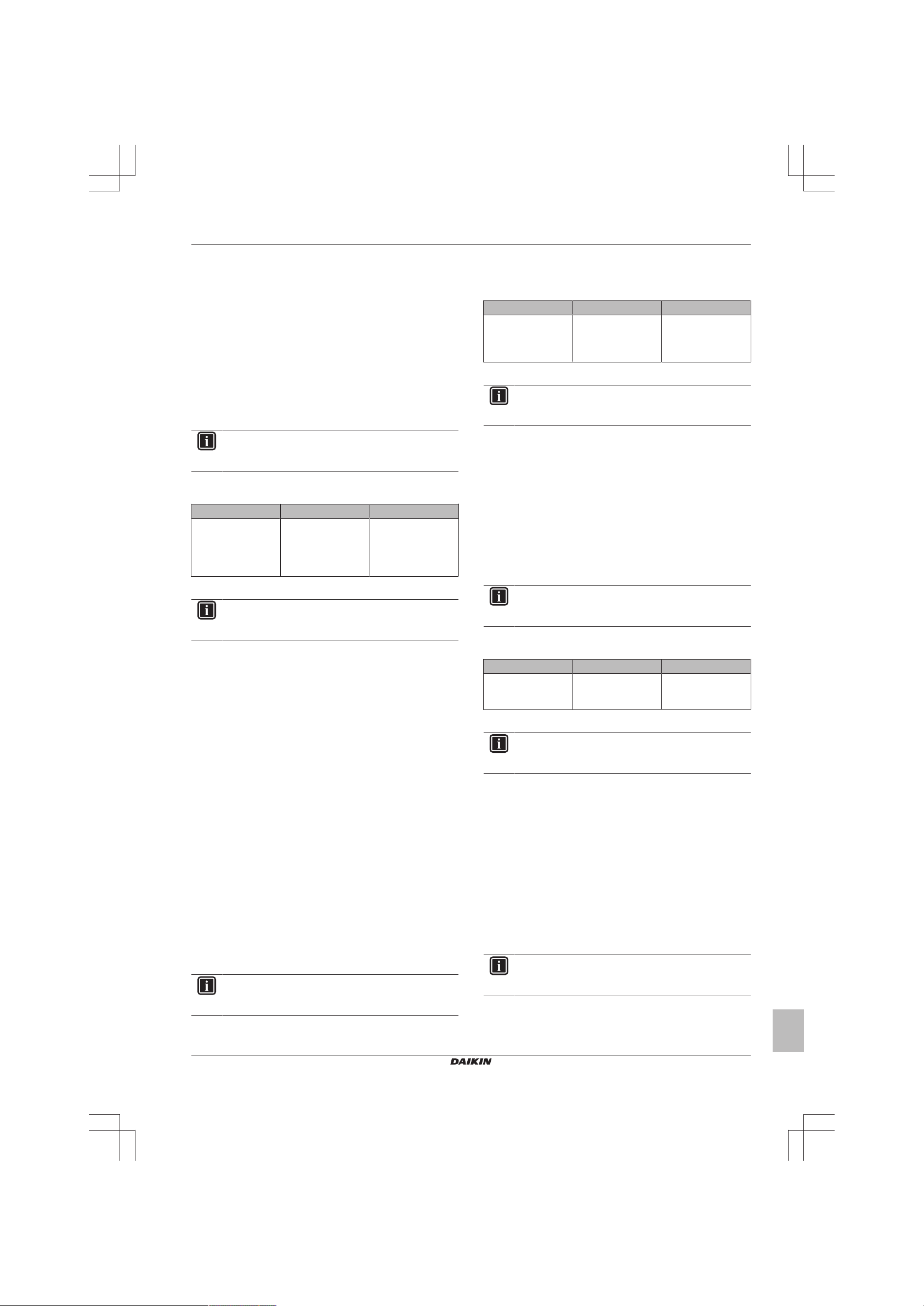
1.5.13 E7-00 – Fan lock abnormality
Trigger Effect Reset
Fan does NOT start
15~30seconds after
ON signal.
It can occur that the
error code is
triggered when the
fan motor is running
caused by a faulty
rotating sensor
signal.
To solve the error code
INFORMATION
It is recommended to perform the checks in the listed
order.
1 Perform a check of the outdoor unit fan motor. See
"2.12Outdoor unit fan motor"on page38.
Possible cause: Faulty outdoor unit fan motor.
2 Perform a check of the inverter PCB. See "2.10 Inverter
PCB"on page34.
Possible cause: Faulty power module = inverter PCB.
INFORMATION
If all procedures listed above have been performed and the
problem is still present, contact the helpdesk.
Unit will stop
operating.
Manual reset via user
interface.
1.5.14 E8-00 – Input overvoltage abnormality
Trigger Effect Reset
Compressor running
current exceeds
standard value for
2.5seconds.
To solve the error code
INFORMATION
It is recommended to perform the checks in the listed
order.
1 Check the outdoor temperature. See "3.3 External factors"on
page55.
Possible cause: Outdoor temperature is out of operation
range.
2 Perform a check of the compressor. See "2.2Compressor" on
page20.
Possible cause: Faulty compressor.
3 Perform a check of the inverter PCB. See "2.10 Inverter
PCB"on page34.
Possible cause: Faulty power module = inverter PCB.
4 Check if the power supply is conform with the regulations. See
"3.1Power supply"on page52.
Possible cause:
▪ Faulty or disturbance of the power supply (imbalance
>10%),
▪ Power drop,
▪ Short circuit.
INFORMATION
If all procedures listed above have been performed and the
problem is still present, contact the helpdesk.
Unit will stop
operating.
Manual reset via user
interface.
1.5.15 EA-00 – Cooling/Heating switch abnormality
Trigger Effect Reset
Room thermistor is
NOT functioning
within operation
range.
To solve the error code
INFORMATION
It is recommended to perform the checks in the listed
order.
1 Perform a check of the 4‑way valve. See "2.14-way valve"on
page18.
Possible cause: Faulty 4‑way valve.
2 Perform a check of the main PCB. See "2.11 Main PCB"on
page35.
Possible cause: Faulty main PCB.
3 Perform a check of the room thermistor. See
"2.18Thermistors"on page49.
Possible cause: Faulty room thermistor.
4 Perform a check of the refrigerant circuit. See "3.2 Refrigerant
circuit"on page53.
Possible cause:
▪ Stop valve is closed,
▪ Clogged refrigerant circuit,
▪ Refrigerant circuit NOT charged correctly,
▪ Humidity in the refrigerant circuit,
▪ Non-condensables in the refrigerant circuit,
▪ Leaking refrigerant circuit.
INFORMATION
If all procedures listed above have been performed and the
problem is still present, contact the helpdesk.
Unit will NOT stop
operating.
If the error occurs too
soon: unit will stop
operating.
Automatic reset after
a continuous
operation of
10minutes.
Manual reset via user
interface.
1.5.16 F3-00 – Discharge pipe temperature stop abnormality
Trigger Effect Reset
Discharge pipe
thermistor detects a
too high temperature.
To solve the error code
INFORMATION
It is recommended to perform the checks in the listed
order.
1 Perform a check of the refrigerant circuit. See "3.2 Refrigerant
circuit"on page53.
Possible cause:
▪ Stop valve is closed,
▪ Clogged refrigerant circuit,
▪ Refrigerant circuit NOT charged correctly,
▪ Humidity in the refrigerant circuit,
▪ Non-condensables in the refrigerant circuit,
▪ Leaking refrigerant circuit.
Unit will NOT stop
operating.
If the error re-occurs
too soon: unit will
stop operating.
Automatic reset when
temperature drops
normal level.
Manual reset via user
interface.
Service manual
8
(C)(F)TXA15~50A2V1B(W)(S)(T) + RXA42+50A2V1B +
RXA20~35A2V1B
Split Stylish R32
ESIE18-03 – 2018.09
1 Troubleshooting
2 Perform a check of the 4‑way valve. See "2.14-way valve"on
page18.
Possible cause: Faulty 4‑way valve.
3 Perform a check of the expansion valve. See "2.3 Expansion
valve"on page23.
Possible cause: Faulty expansion valve.
4 Perform a check of the main PCB. See "2.11 Main PCB"on
page35.
Possible cause: Faulty main PCB.
5 Perform a check of all refrigerant thermistors. See
"2.18Thermistors"on page49.
Possible cause: Faulty refrigerant thermistor(s).
INFORMATION
If all procedures listed above have been performed and the
problem is still present, contact the helpdesk.
1.5.17 F6-00 – Stop due to cooling high pressure
Trigger Effect Reset
Outdoor heat
exchanger thermistor
measures
temperature
>60°C~65°C
To solve the error code
INFORMATION
It is recommended to perform the checks in the listed
order.
1 Clean the outdoor heat exchanger. See "4 Maintenance" on
page56.
Possible cause: Dirty outdoor heat exchanger.
2 Perform a check of the refrigerant circuit. See "3.2 Refrigerant
circuit"on page53.
Possible cause:
▪ Stop valve is closed,
▪ Clogged refrigerant circuit,
▪ Refrigerant circuit NOT charged correctly,
▪ Humidity in the refrigerant circuit,
▪ Non-condensables in the refrigerant circuit,
▪ Leaking refrigerant circuit.
3 Perform a check of the heat exchanger thermistor. See
"2.18Thermistors"on page49.
Possible cause: Faulty heat exchanger thermistor.
4 Perform a check of the expansion valve. See "2.3 Expansion
valve"on page23.
Possible cause: Faulty expansion valve.
5 Perform a check of the main PCB. See "2.11 Main PCB"on
page35.
Possible cause: Faulty main PCB.
6 Perform a check of the outdoor unit fan motor. See
"2.12Outdoor unit fan motor"on page38.
Possible cause: Faulty outdoor unit fan motor.
INFORMATION
If all procedures listed above have been performed and the
problem is still present, contact the helpdesk.
Unit will NOT stop
operating.
Automatic reset when
temperature drops
below 50°C.
1.5.18 F8-00 – System shutdown due to compressor internal temperature abnormality
Trigger Effect Reset
Temperature
discharge pipe
thermistor exceeds
the determined limit.
To solve the error code
INFORMATION
It is recommended to perform the checks in the listed
order.
1 Perform a check of the refrigerant circuit. See "3.2 Refrigerant
circuit"on page53.
Possible cause:
▪ Stop valve is closed,
▪ Clogged refrigerant circuit,
▪ Refrigerant circuit NOT charged correctly,
▪ Humidity in the refrigerant circuit,
▪ Non-condensables in the refrigerant circuit,
▪ Leaking refrigerant circuit.
2 Perform a check of the discharge pipe thermistor. See
"2.18Thermistors"on page49.
Possible cause: Faulty discharge pipe thermistor.
INFORMATION
If all procedures listed above have been performed and the
problem is still present, contact the helpdesk.
Unit will stop
operating.
Manual reset via user
interface.
1.5.19 H0-00 – Current sensor abnormality
Trigger Effect Reset
Compressor voltage
(DC) is out of range
before start‑up.
To solve the error code
INFORMATION
It is recommended to perform the checks in the listed
order.
1 Perform a check of the main PCB. See "2.11 Main PCB"on
page35.
Possible cause: Faulty main PCB.
2 Perform a check of the inverter PCB. See "2.10 Inverter
PCB"on page34.
Possible cause: Faulty power module = inverter PCB.
3 Check if the power supply is conform with the regulations. See
"3.1Power supply"on page52.
Possible cause:
▪ Faulty or disturbance of the power supply (imbalance
>10%),
▪ Power drop,
▪ Short circuit.
INFORMATION
If all procedures listed above have been performed and the
problem is still present, contact the helpdesk.
Unit will stop
operating.
Manual reset via user
interface.
(C)(F)TXA15~50A2V1B(W)(S)(T) + RXA42+50A2V1B +
RXA20~35A2V1B
Split Stylish R32
ESIE18-03 – 2018.09
Service manual
9
1 Troubleshooting
1.5.20 H3-00 – High pressure switch defect
Trigger Effect Reset
High pressure switch
is activated when
compressor is off.
To solve the error code
INFORMATION
It is recommended to perform the checks in the listed
order.
1 Perform a check of the high pressure switch. See "2.5 High
pressure switch"on page27.
Possible cause: Faulty high pressure switch.
2 Perform a check of the refrigerant circuit. See "3.2 Refrigerant
circuit"on page53.
Possible cause:
▪ Stop valve is closed,
▪ Clogged refrigerant circuit,
▪ Refrigerant circuit NOT charged correctly,
▪ Humidity in the refrigerant circuit,
▪ Non-condensables in the refrigerant circuit,
▪ Leaking refrigerant circuit.
3 Perform a check of the main PCB. See "2.11 Main PCB"on
page35.
Possible cause: Faulty main PCB.
4 Perform a check of the inverter PCB. See "2.10 Inverter
PCB"on page34.
Possible cause: Faulty power module = inverter PCB.
5 Check if the power supply is conform with the regulations. See
"3.1Power supply"on page52.
Possible cause:
▪ Faulty or disturbance of the power supply (imbalance
>10%),
▪ Power drop,
▪ Short circuit.
INFORMATION
If all procedures listed above have been performed and the
problem is still present, contact the helpdesk.
Unit will stop
operating.
Manual reset via user
interface.
1.5.21 H6-00 – Location detection sensor abnormality
Trigger Effect Reset
Compressor fails to
start within
15seconds after the
compressor run
command signal is
sent.
To solve the error code
INFORMATION
It is recommended to perform the checks in the listed
order.
1 Perform a check of the compressor. See "2.2Compressor" on
page20.
Possible cause: Faulty compressor.
2 Perform a check of the main PCB. See "2.11 Main PCB"on
page35.
Unit will NOT stop
operating.
If the error re-occurs
within 8minutes: unit
will stop operating.
Automatic reset after
a continuous
operation of
10minutes.
Manual reset via user
interface.
Possible cause: Faulty main PCB.
3 Perform a check of the inverter PCB. See "2.10 Inverter
PCB"on page34.
Possible cause: Faulty power module = inverter PCB.
4 Perform a check of the refrigerant circuit. See "3.2 Refrigerant
circuit"on page53.
Possible cause:
▪ Stop valve is closed,
▪ Clogged refrigerant circuit,
▪ Refrigerant circuit NOT charged correctly,
▪ Humidity in the refrigerant circuit,
▪ Non-condensables in the refrigerant circuit,
▪ Leaking refrigerant circuit.
5 Check if the power supply is conform with the regulations. See
"3.1Power supply"on page52.
Possible cause:
▪ Faulty or disturbance of the power supply (imbalance
>10%),
▪ Power drop,
▪ Short circuit.
INFORMATION
If all procedures listed above have been performed and the
problem is still present, contact the helpdesk.
1.5.22 H8-00 – Compressor input abnormality
Trigger Effect Reset
DC voltage or current
sensor abnormality
based on the
compressor running
frequency and the
input current.
To solve the error code
INFORMATION
It is recommended to perform the checks in the listed
order.
1 Perform a check of the main PCB. See "2.11 Main PCB"on
page35.
Possible cause: Faulty main PCB.
2 Perform a check of the inverter PCB. See "2.10 Inverter
PCB"on page34.
Possible cause: Faulty power module = inverter PCB.
3 Perform a check of the compressor. See "2.2Compressor" on
page20.
Possible cause: Faulty compressor.
4 Perform a check of the reactor. See "2.14 Reactor" on
page44.
Possible cause: Faulty reactor.
INFORMATION
If all procedures listed above have been performed and the
problem is still present, contact the helpdesk.
Unit will NOT stop
operating.
If the error re-occurs
too soon: unit will
stop operating.
Automatic reset when
compressor runs
normally for
60minutes.
Manual reset via user
interface.
Service manual
10
(C)(F)TXA15~50A2V1B(W)(S)(T) + RXA42+50A2V1B +
RXA20~35A2V1B
Split Stylish R32
ESIE18-03 – 2018.09
1 Troubleshooting
1.5.23 H9-00 – Outdoor air thermistor abnormality
Trigger Effect Reset
Outdoor air thermistor
input is out of range.
To solve the error code
INFORMATION
It is recommended to perform the checks in the listed
order.
1 Perform a check of the outdoor air thermistor. See
"2.18Thermistors"on page49.
Possible cause: Faulty outdoor air thermistor.
2 Perform a check of the main PCB. See "2.11 Main PCB"on
page35.
Possible cause: Faulty main PCB.
INFORMATION
If all procedures listed above have been performed and the
problem is still present, contact the helpdesk.
Unit will stop
operating.
Manual reset via user
interface.
1.5.24 J3-00 – Discharge pipe thermistor dislocation abnormality
Trigger Effect Reset
Discharge pipe
thermistor input is out
of range.
To solve the error code
INFORMATION
It is recommended to perform the checks in the listed
order.
1 Perform a check of the discharge pipe thermistor. See
"2.18Thermistors"on page49.
Possible cause: Faulty discharge pipe thermistor.
2 Perform a check of the main PCB. See "2.11 Main PCB"on
page35.
Possible cause: Faulty main PCB.
Unit will stop
operating.
Manual reset via user
interface.
2 Perform a check of the main PCB. See "2.11 Main PCB"on
page35.
Possible cause: Faulty main PCB.
INFORMATION
If all procedures listed above have been performed and the
problem is still present, contact the helpdesk.
1.5.26 L3-00 – Electrical component temperature abnormality
Trigger Effect Reset
Switch box
temperature is too
high.
To solve the error code
INFORMATION
It is recommended to perform the checks in the listed
order.
1 Perform a check of the inverter PCB. See "2.10 Inverter
PCB"on page34.
Possible cause: Faulty power module = inverter PCB.
2 Perform a check of the outdoor unit fan motor. See
"2.12Outdoor unit fan motor"on page38.
Possible cause: Faulty outdoor unit fan motor.
3 Check if the power supply is conform with the regulations. See
"3.1Power supply"on page52.
Possible cause:
▪ Faulty or disturbance of the power supply (imbalance
>10%),
▪ Power drop,
▪ Short circuit.
4 Clean the outdoor heat exchanger. See "4 Maintenance" on
page56.
Possible cause: Dirty outdoor heat exchanger.
INFORMATION
If all procedures listed above have been performed and the
problem is still present, contact the helpdesk.
Unit will stop
operating.
Manual reset via
remote controller.
INFORMATION
If all procedures listed above have been performed and the
problem is still present, contact the helpdesk.
1.5.25 J6-00 – Outdoor heat exchanger thermistor abnormality
Trigger Effect Reset
Outdoor heat
exchanger thermistor
input is out of range.
To solve the error code
INFORMATION
It is recommended to perform the checks in the listed
order.
1 Perform a check of the heat exchanger thermistor. See
"2.18Thermistors"on page49.
Possible cause: Faulty heat exchanger thermistor.
(C)(F)TXA15~50A2V1B(W)(S)(T) + RXA42+50A2V1B +
RXA20~35A2V1B
Split Stylish R32
ESIE18-03 – 2018.09
Unit will stop
operating.
Manual reset via user
interface.
1.5.27 L4-00 – Fin temperature increase abnormality
Trigger Effect Reset
Radiating fin
thermistor measures
a too high
temperature.
To solve the error code
INFORMATION
It is recommended to perform the checks in the listed
order.
1 Perform a check of the outdoor unit fan motor. See
"2.12Outdoor unit fan motor"on page38.
Possible cause: Faulty outdoor unit fan motor.
2 Check if the power supply is conform with the regulations. See
"3.1Power supply"on page52.
Unit will stop
operating.
Manual reset via user
interface.
Service manual
11
1 Troubleshooting
Possible cause:
▪ Faulty or disturbance of the power supply (imbalance
>10%),
▪ Power drop,
▪ Short circuit.
3 Perform a check of the inverter PCB. See "2.10 Inverter
PCB"on page34.
Possible cause: Faulty power module = inverter PCB.
4 Perform a check of the main PCB. See "2.11 Main PCB"on
page35.
Possible cause: Faulty main PCB.
5 Check that the silicon grease is applied properly on the
radiation fin of the outdoor unit PCB. Adjust if needed.
Possible cause: Silicon grease NOT applied properly on the
radiation fin.
INFORMATION
If all procedures listed above have been performed and the
problem is still present, contact the helpdesk.
1.5.28 L5-00 – Output over current abnormality
Trigger Effect Reset
An output overcurrent
is detected by
checking the current
that flows in the
inverter DC section.
To solve the error code
INFORMATION
It is recommended to perform the checks in the listed
order.
1 Perform a check of the refrigerant circuit. See "3.2 Refrigerant
circuit"on page53.
Possible cause:
▪ Stop valve is closed,
▪ Clogged refrigerant circuit,
▪ Refrigerant circuit NOT charged correctly,
▪ Humidity in the refrigerant circuit,
▪ Non-condensables in the refrigerant circuit,
▪ Leaking refrigerant circuit.
2 Perform a check of the inverter PCB. See "2.10 Inverter
PCB"on page34.
Possible cause: Faulty power module = inverter PCB.
3 Perform a check of the compressor. See "2.2Compressor" on
page20.
Possible cause: Faulty compressor.
4 Check if the power supply is conform with the regulations. See
"3.1Power supply"on page52.
Possible cause:
▪ Faulty or disturbance of the power supply (imbalance
>10%),
▪ Power drop,
▪ Short circuit.
INFORMATION
If all procedures listed above have been performed and the
problem is still present, contact the helpdesk.
Unit will stop
operating.
Manual reset via user
interface.
1.5.29 P4-00 – Fin thermistor abnormality
Trigger Effect Reset
Radiating fin
thermistor input is out
of range.
To solve the error code
INFORMATION
It is recommended to perform the checks in the listed
order.
1 Perform a check of the inverter PCB. See "2.10 Inverter
PCB"on page34.
Possible cause: Faulty power module = inverter PCB.
2 Perform a check of the main PCB. See "2.11 Main PCB"on
page35.
Possible cause: Faulty main PCB.
INFORMATION
If all procedures listed above have been performed and the
problem is still present, contact the helpdesk.
Unit will stop
operating.
Manual reset via user
interface.
1.5.30 U0-00 – Shortage of refrigerant
Trigger Effect Reset
Refrigerant shortage
detected.
To solve the error code
INFORMATION
It is recommended to perform the checks in the listed
order.
1 Perform a check of all refrigerant thermistors. See
"2.18Thermistors"on page49.
Possible cause: Faulty refrigerant thermistor(s).
2 Perform a check of the refrigerant circuit. See "3.2 Refrigerant
circuit"on page53.
Possible cause:
▪ Stop valve is closed,
▪ Clogged refrigerant circuit,
▪ Refrigerant circuit NOT charged correctly,
▪ Humidity in the refrigerant circuit,
▪ Non-condensables in the refrigerant circuit,
▪ Leaking refrigerant circuit.
3 Perform a check of the compressor. See "2.2Compressor" on
page20.
Possible cause: Faulty compressor.
4 Perform a check of the expansion valve. See "2.3 Expansion
valve"on page23.
Possible cause: Faulty expansion valve.
INFORMATION
If all procedures listed above have been performed and the
problem is still present, contact the helpdesk.
Unit will stop
operating.
Automatic reset.
Power reset via
outdoor unit.
Service manual
12
(C)(F)TXA15~50A2V1B(W)(S)(T) + RXA42+50A2V1B +
RXA20~35A2V1B
Split Stylish R32
ESIE18-03 – 2018.09
1 Troubleshooting
1.5.31 U2-00 – Main circuit voltage abnormality
Trigger Effect Reset
Power supply
abnormality or instant
power failure is
detected.
To solve the error code
INFORMATION
It is recommended to perform the checks in the listed
order.
INFORMATION
In case of preferential kWh rate, the indoor unit also needs
a power reset.
1 Check if the power supply is conform with the regulations. See
"3.1Power supply"on page52.
Possible cause:
▪ Faulty or disturbance of the power supply (imbalance
>10%),
▪ Power drop,
▪ Short circuit.
2 Perform a check of the compressor. See "2.2Compressor" on
page20.
Possible cause: Faulty compressor.
3 Perform a check of the outdoor unit fan motor. See
"2.12Outdoor unit fan motor"on page38.
Possible cause: Faulty outdoor unit fan motor.
4 Perform a check of the main PCB. See "2.11 Main PCB"on
page35.
Possible cause: Faulty main PCB.
5 Perform a check of the indoor unit PCB. See "2.8Indoor unit
PCB"on page30.
Possible cause: Faulty indoor unit PCB.
6 Wait until the compressor restarts.
Possible cause:
▪ Momentary drop of voltage,
▪ Momentary power failure.
INFORMATION
If all procedures listed above have been performed and the
problem is still present, contact the helpdesk.
Unit will stop
operating.
Power reset via
outdoor unit.
1.5.32 U4-00 – Indoor/outdoor transmission abnormality
Trigger Effect Reset
Communication
failure between
outdoor and indoor
unit.
Unit will stop
operating.
Power reset via
outdoor unit.
1 Check if the power supply is conform with the regulations. See
"3.1Power supply"on page52.
Possible cause:
▪ Faulty or disturbance of the power supply (imbalance
>10%),
▪ Power drop,
▪ Short circuit.
2 Perform a check of the power supply, connections, wiring,…
between the outdoor unit and the indoor unit. See "3.1Power
supply"on page52.
Possible cause: Faulty wiring between the outdoor unit and
the indoor unit.
3 Perform a check of the main PCB. See "2.11 Main PCB"on
page35.
Possible cause: Faulty main PCB.
4 Perform a check of the outdoor unit fan motor. See
"2.12Outdoor unit fan motor"on page38.
Possible cause: Faulty outdoor unit fan motor.
5 Perform a check of the indoor unit PCB. See "2.8Indoor unit
PCB"on page30.
Possible cause: Faulty indoor unit PCB.
INFORMATION
If all procedures listed above have been performed and the
problem is still present, contact the helpdesk.
1.5.33 U5-00 – Transmission malfunction between indoor unit and remote controller
Trigger Effect Reset
Communication
failure between
indoor unit and user
interface.
To solve the error code
INFORMATION
It is recommended to perform the checks in the listed
order.
1 Check for improper combination of the indoor unit and the
remote controller. See Business Portal for more information.
2 Check the wiring between the indoor unit and remote controller.
See "3.1Power supply"on page52.
Possible cause: Faulty wiring between the indoor unit and
remote controller.
INFORMATION
If all procedures listed above have been performed and the
problem is still present, contact the helpdesk.
Unit will stop
operating.
Automatic reset.
1.5.34 UA-00 – Indoor/outdoor combination abnormality
To solve the error code
INFORMATION
It is recommended to perform the checks in the listed
order.
INFORMATION
In case of preferential kWh rate, the indoor unit also needs
a power reset.
(C)(F)TXA15~50A2V1B(W)(S)(T) + RXA42+50A2V1B +
RXA20~35A2V1B
Split Stylish R32
ESIE18-03 – 2018.09
Trigger Effect Reset
Signal transmission
between outdoor and
indoor unit
abnormality. Improper
combination of
outdoor and indoor
unit.
Unit will stop
operating.
Power reset via
outdoor unit.
Service manual
13
1 Troubleshooting
To solve the error code
INFORMATION
It is recommended to perform the checks in the listed
order.
INFORMATION
In case of preferential kWh rate, the indoor unit also needs
a power reset.
1 Check for improper combination of the indoor unit and the
outdoor unit. See the combination table in the Databook for
more information.
2 Perform a check of the power supply, connections, wiring,…
between the outdoor unit and the indoor unit. See "3.1Power
supply"on page52.
Possible cause: Faulty wiring between the outdoor unit and
the indoor unit.
3 Perform a check of the main PCB. See "2.11 Main PCB"on
page35.
Possible cause: Faulty main PCB.
4 Perform a check of the indoor unit PCB. See "2.8Indoor unit
PCB"on page30.
Possible cause: Faulty indoor unit PCB.
INFORMATION
If all procedures listed above have been performed and the
problem is still present, contact the helpdesk.
Service manual
14
(C)(F)TXA15~50A2V1B(W)(S)(T) + RXA42+50A2V1B +
RXA20~35A2V1B
Split Stylish R32
ESIE18-03 – 2018.09
1.6 Symptom based troubleshooting
1 Troubleshooting
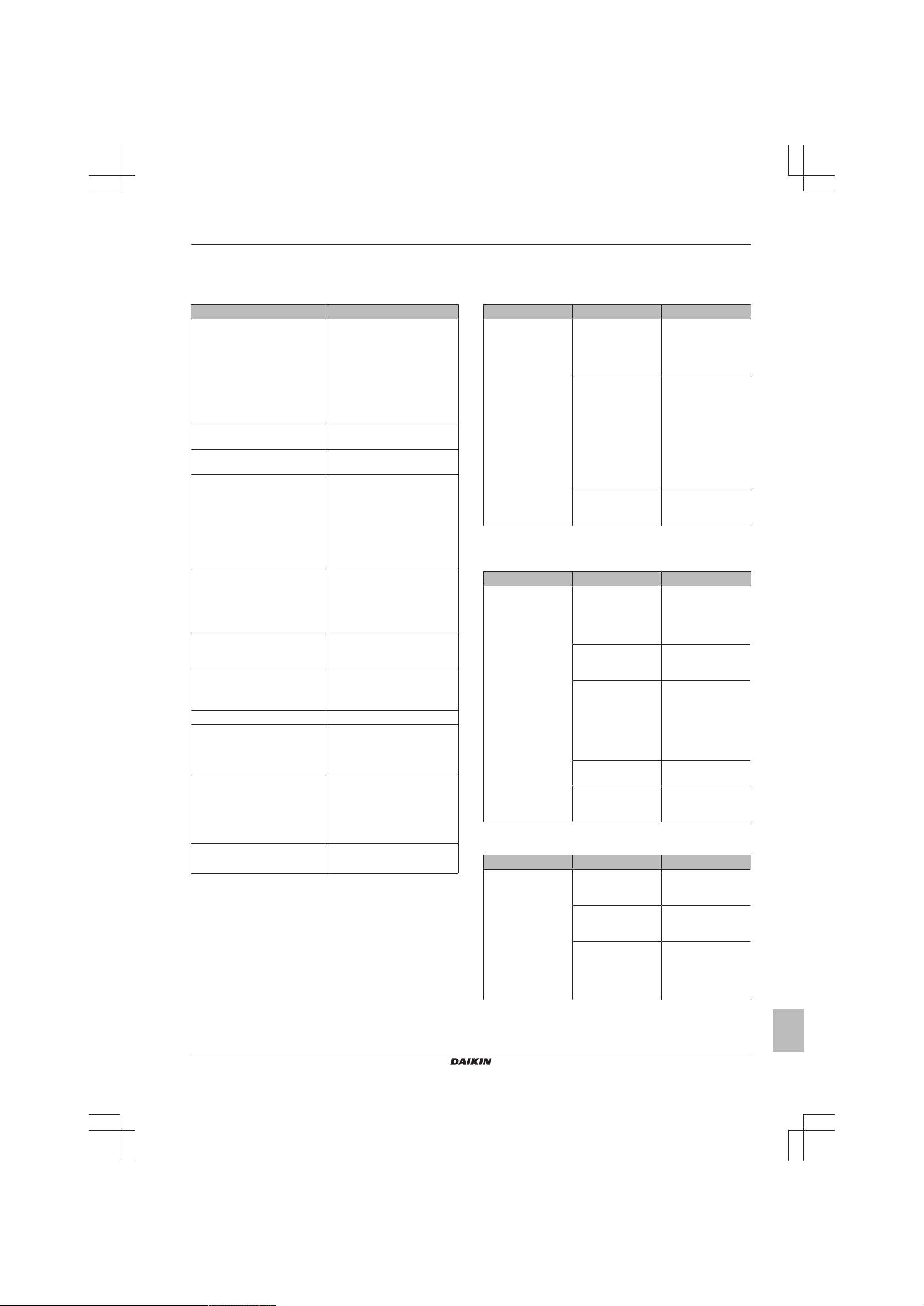
1.6.1 Operation does not start
Check Detail
When the operation lamp is off,
there is a power failure.
Check the power supply.
Check the type of the indoor unit. Is the indoor unit type compatible
Check the transmission between
indoor and outdoor
Check the outdoor temperature. ▪ Heating operation cannot be
When the operation lamp blinks,
there may be an error code,
activating the protection device.
Diagnose with remote controller
indication.
Check the remote controller
addresses.
Check the operation circuit. ▪ Is the thermal fuse blown.
Check high pressure switch. Not available
Check fan motor. ▪ Is the magnetic switch
Check compressor. ▪ Is the contact defective?
Check remote controller. ▪ Are the batteries LOW?
▪ Is the power supply breaker
ON?
▪ Do other electrical appliances
work?
▪ Is the rated voltage (± 10%) is
supplied?
▪ Check the insulation of the
electric system.
with the outdoor unit?
▪
used when the outdoor
temperature is 18°C WB or
higher.
▪ Cooling operation cannot be
used when the outdoor
temperature is below –
10°CDB.
See "1.5Error based
troubleshooting"on page4.
Are the address settings for the
remote controller and indoor unit
correct?
▪ Are wire size and wire
connections OK?.
defective?
▪ Is the overcurrent relay
defective?
▪ Is the protection thermostat
defective?
▪ Is the compressor itself
defective?
▪ Are there incorrect settings?
1.6.2 Operation sometimes stops
Symptom Check Detail
Operation sometimes
stops
Check the power
supply.
Check the outdoor
temperature.
Diagnose with remote
controller indication.
A power failure of 2 to
10 cycles stops air
conditioner operation.
(Operation lamp
OFF)
Heating operation
cannot be used when
the outdoor
temperature is
18°CWB or higher,
and cooling operation
cannot be used when
the outdoor
temperature is below
–10°CDB.
{Jesse Victoor,
12/01/2018
09:43:04: ???}
1.6.3 Operation starts but the unit does not cool/heat
Symptom Check Detail
Operation starts and
the unit does not
cool/heat
Check for wiring and
piping errors in the
connection between
the indoor unit and
outdoor unit.
Check for thermistor
detection errors.
Check for faulty
operation of the
electronic expansion
valve.
Diagnose with remote
controller indication.
Diagnose by service
port pressure and
operating current.
Not applicable
Check if the
thermistor is mounted
securely.
Set the unit to cooling
operation, and check
the temperature of
the liquid pipe to see
if the electronic
expansion valve
works.
Not applicable
Check for refrigerant
shortage.
1.6.4 Operating noise and vibrations
Symptom Check Detail
Operating noise and
vibrations
Check the output
voltage of the power
module.
Check the power
module.
Check the installation
condition.
{Jesse Victoor,
12/01/2018
09:41:35: ???}
{Jesse Victoor,
12/01/2018
09:41:35: ???}
Check if the required
spaces for installation
(specified in the
installation manual)
are provided.
(C)(F)TXA15~50A2V1B(W)(S)(T) + RXA42+50A2V1B +
RXA20~35A2V1B
Split Stylish R32
ESIE18-03 – 2018.09
Service manual
15
1 Troubleshooting
Symptom Check Detail
{Jesse Victoor,
12/01/2018
09:41:41: ????}
Check refrigerant
charge.
▪ Overcharge
▪ Air in the system
▪ Flushing noise, due
to refrigerant
shortage
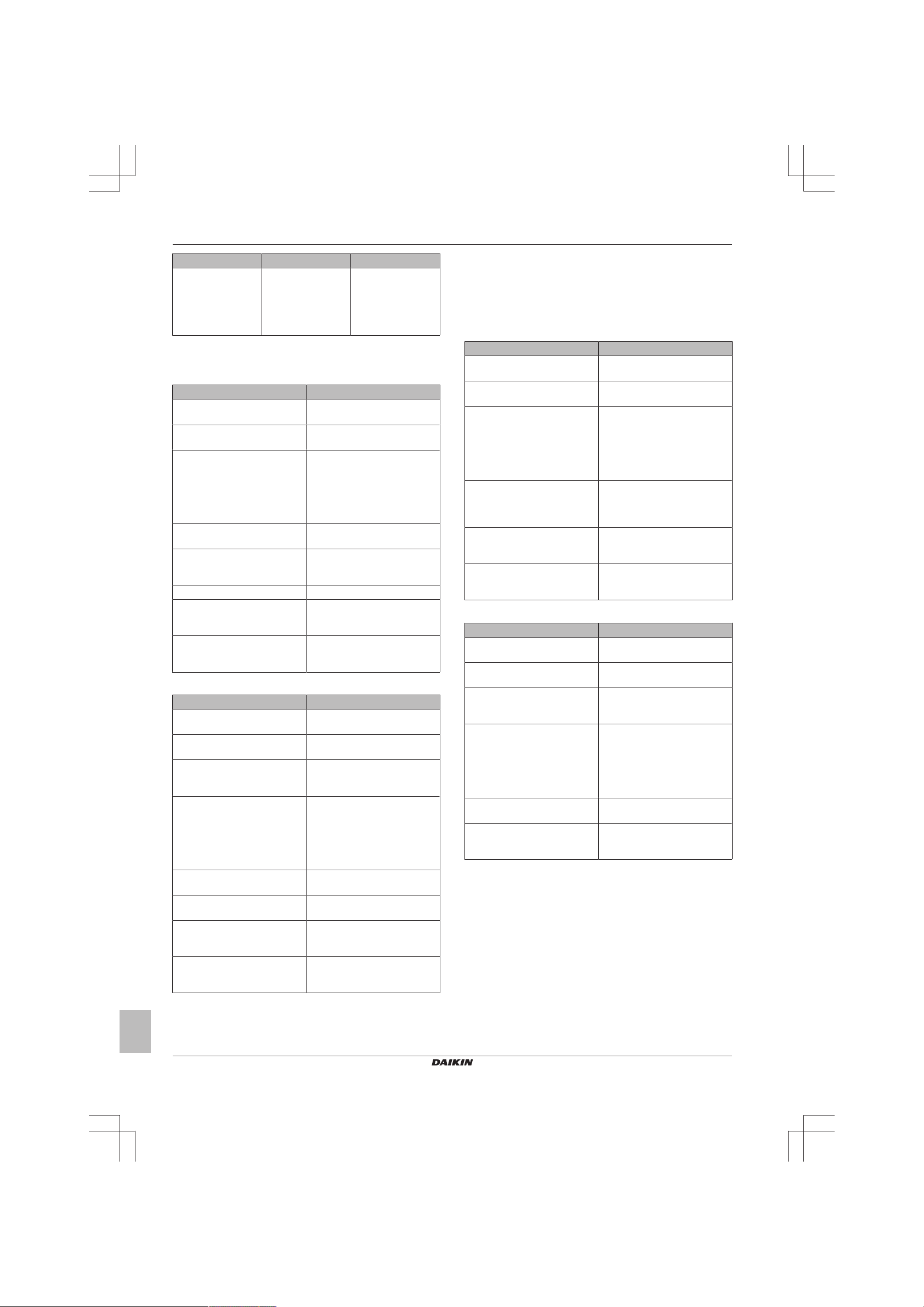
1.6.5 Abnormal high pressure
In cooling mode
Check item Detail
Does the outdoor unit fan run
normally?
Is the outdoor unit heat
exchanger clogged?
Is there clogging before or after
the expansion valve (capillary)?
Is the High Pressure Switch
normal?
Is the outdoor unit installed under
such conditions that short circuit
easily occurs?
Is the piping length ≤5m? Visual inspection
Does air enter the refrigerant
system?
Is the refrigerant overcharged? Conduct refrigerant collection
In cooling mode
Check item Detail
Does the indoor unit fan run
normally?
Is the indoor unit heat exchanger
clogged?
Is the indoor unit installed under
such conditions that short circuit
easily occurs?
Is there clogging before or after
the expansion valve (capillary)?
Is the High Presure Switch
normal?
Is the minimum piping length
respected?
Does air enter the refrigerant
system?
Is the refrigerant overcharged? Conduct refrigerant collection
Visual inspection
Visual inspection
▪ Check if there is a temperature
difference before and after
expansion valve (capillary).
▪ Check if the main valve unit of
expansion valve operates (by
noise, vibration).
Check continuity by using a
tester.
Visual inspection
Conduct refrigerant collection
and vacuum drying, and then
add proper amount refrigerant.
and vacuum drying, and then
add proper amount refrigerant.
Visual inspection
Visual inspection
Visual inspection
▪ Check if there is a temperature
difference before and after
expansion valve (capillary).
▪ Check if the main valve unit of
expansion valve operates (by
noise, vibration).
Check continuity by using a
tester.
Visual inspection
Conduct refrigerant collection
and vacuum drying, and then
add proper amount refrigerant.
and vacuum drying, and then
add proper amount refrigerant.
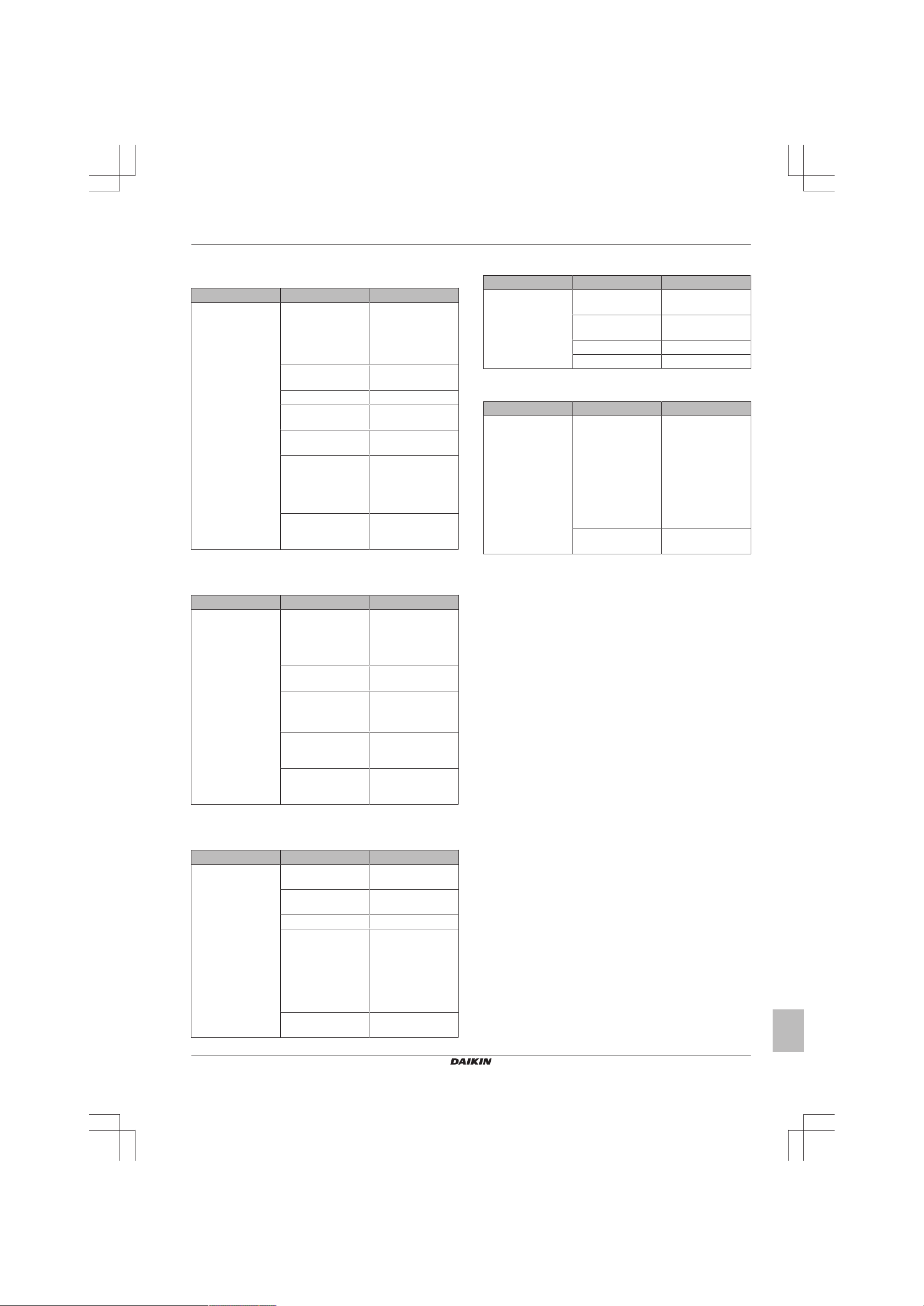
1.6.6 Abnormal low pressure
Abnormally low pressure level is mostly caused by the evaporator
side. The following contents are provided based on field checking of
service engineer. Further, the number is listed in the order of degree
of influence.
In cooling mode
Check item Detail
Does the outdoor unit fan run
normally?
Is the indoor unit heat exchanger
clogged?
Is there clogging before or after
the expansion valve (capillary)?
Is the check valve clogged? Check if there is a temperature
Is the indoor unit installed under
such conditions that short circuit
easily occurs?
Is the refrigerant gas short? Conduct refrigerant collection
In cooling mode
Check item Detail
Does the outdoor unit fan run
normally?
Is the outdoor unit heat
exchanger clogged?
Is the outdoor unit installed under
such conditions that short circuit
easily occurs?
Is there clogging before or after
the expansion valve (capillary)?
Is the check valve clogged? after check valve. If YES, the
Is the refrigerant gas short? Conduct refrigerant collection
Visual inspection
Visual inspection
▪ Check if there is a temperature
difference before and after
expansion valve (capillary).
▪ Check if the main valve unit of
expansion valve operates (by
noise, vibration).
difference before and after check
valve. If YES, the check valve is
caught.
Visual inspection
and vacuum drying, and then
add proper amount refrigerant.
Visual inspection
Visual inspection
Visual inspection
▪ Check if there is a temperature
difference before and after
expansion valve (capillary).
▪ Check if the main valve unit of
expansion valve operates (by
noise, vibration).
check valve is caught.
and vacuum drying, and then
add proper amount refrigerant.
Service manual
16
(C)(F)TXA15~50A2V1B(W)(S)(T) + RXA42+50A2V1B +
RXA20~35A2V1B
Split Stylish R32
ESIE18-03 – 2018.09
1 Troubleshooting
1.6.7 Indoor fan starts operating but the compressor does not operate
Symptom Check Detail
Indoor fan starts
operating,
compressor does not
operate
Check power supply ▪ Check if the rated
voltage is supplied.
▪ Check the
insulation of the
electric system.
Check thermistor Connection witch
PCB, output.
Check PCB's HAP LED.
Check magnetic
switch
Check power
transistor
Check compressor Defective contact,
defective
compressor,
defective protection
thermostat.
Check operation
range
Is the outdoor
temperature within
the limit.
1.6.8 Operation starts and the unit stops immediately
1.6.10 Unit discharges white mist
Symptom Check Detail
Unit discharges white
mist
Check installation
conditions
Check heat
exchanger
Air filter Dirty air filter
Fan motor Defective fan motor
Humid site, dirty site,
oil mist
Dirty heat exchanger
1.6.11 Swing flap does not operate
Symptom Check Detail
Swing flap does not
operate
Check swing flap
motor
Check indoor unit
PCB
Some functions can
force the swing flap
into a fixed position,
although swing mode
is selected on the
remote controller.
This is not a unit
error, but a control
function to prevent
draft to the customer.
Connector connection
Symptom Check Detail
Operation starts and
the unit stops
immediately
Check refrigerant
charge
Check pressure
switch
Check fan motor ▪ Check magnetic
Check heat
exchanger
Check airflow Soiled air filter,
▪ Overcharge
▪ Air in the system
▪ Water in the
system
Not available
switch
▪ Operation
Soiled heat
exchanger,
obstruction.
obstruction,
installation space.
1.6.9 Operation stops, unit cannot start for a while
Symptom Check Detail
Operation stops, the
unit cannot start for a
while
Check compressor Overcurrent relay,
protection thermostat
Check power supply Low voltage, size of
power cable
Check high pressure
Check refrigerant
charge
Compressor delay
timer is counting.
▪ Air in the system
▪ Incorrect charge
▪ Water in the
system
▪ Obstruction in the
system
Wait for minimum 3
minutes.
(C)(F)TXA15~50A2V1B(W)(S)(T) + RXA42+50A2V1B +
RXA20~35A2V1B
Split Stylish R32
ESIE18-03 – 2018.09
Service manual
17
2 Components
2 Components
2.1 4-way valve
2.1.1 Checking procedures
INFORMATION
It is recommended to perform the checks in the listed
order.
To perform a mechanical check of the 4-way valve
Prerequisite: Turn OFF the unit via the user interface.
Prerequisite: Turn OFF the respective circuit breaker.
Prerequisite: Remove the required plate work, see "2.13 Plate
work"on page40.
1 Disconnect the 4‑way valve connector from the main PCB.
2 Turn ON the power of the unit.
INFORMATION
Default position of the 4‑way valve is Heating mode.
3 Activate Heating operation via the user interface.
Water temperature after plate
type heat exchanger of the
indoor unit:
Drops 4‑way valve is stuck in cooling
Rises Skip the next step of this
Does NOT rise/drop Perform the next step of this
4 Connect a manifold to one of the service ports of the refrigerant
circuit and check the pressure.
Refrigerant pressure
measured?
Yes Perform a position check of the
No Leaks may be found in the
CAUTION
To prevent damage due to liquid entering the compressor,
the steps below MUST ONLY be executed once.
CAUTION
Make sure you have a pressure difference of at least 6bar
between the high and low pressure when performing this
test.
5 Place a round permanent magnet on the core of the solenoid
valve and listen to the 4‑way valve.
Does the 4‑way valve switch? Action
Yes Perform an electrical check of the
Action
position. Replace the 4‑way
valve body, see "2.1.2Repair
procedures"on page19.
procedure.
procedure.
Action
4‑way valve, see "2.1.1Checking
procedures"on page18.
refrigerant circuit. Perform a
pressure test of the refrigerant
circuit, see "3.2.1Checking
procedures"on page53.
4‑way valve, see "2.1.1Checking
procedures"on page18.
Does the 4‑way valve switch? Action
No Replace the 4‑way valve body,
see "2.1.2Repair procedures"on
page19.
To perform an electrical check of the 4-way valve
1 First perform a mechanical check of the 4‑way valve, see
"2.1.1Checking procedures"on page18.
2 Activate Cooling operation via the user interface.
3 Measure the voltage on the 4‑way valve connector pins 1-3.
The measured voltage MUST be 220~240 V AC during
switching and 12VDC after switching of the 4‑way valve.
Is the measured voltage
correct?
Yes Skip the next step of this
No Perform the next step of this
4 Disconnect the 4‑way valve connector from the main PCB and
measure the voltage on the connector pins 1-3 of the connector
on the main PCB. The voltage MUST be 220~240VAC during
switching and 12VDC after switching.
Is the measured voltage on the
4‑way valve connector of the
main PCB correct?
Yes Replace the 4‑way valve coil, see
No Replace the main PCB, see
5 Disconnect the 4‑way valve connector from the main PCB and
measure the resistance of the 4‑way valve coil. The resistance
MUST be 1000~2000Ω.
Is the measured resistance
correct?
Yes Perform the next step of this
No Replace the 4‑way valve coil, see
6 De-activate Cooling and activate Heating operation via the user
interface.
7 Measure the temperature after the plate type heat exchanger.
Does the measured
temperature rise?
Yes Perform a position check of the
No Replace the main PCB, see
Action
procedure.
procedure.
Action
"2.1.2Repair procedures"on
page19.
"2.11Main PCB"on page35.
Action
procedure.
"2.1.2Repair procedures"on
page19.
Action
4‑way valve, see "2.1.1Checking
procedures"on page18.
"2.11Main PCB"on page35.
To perform a position check of the 4-way valve
1 First perform a mechanical check of the 4‑way valve, see
"2.1.1Checking procedures"on page18.
2 Slide a magnet over the front and rear side of the 4‑way valve
body. The magnet MUST be attracted in the positions a or b,
but NOT in positions c.
Service manual
18
(C)(F)TXA15~50A2V1B(W)(S)(T) + RXA42+50A2V1B +
RXA20~35A2V1B
Split Stylish R32
ESIE18-03 – 2018.09
2 Components
a a
b b
c c
c a b
cd a b a
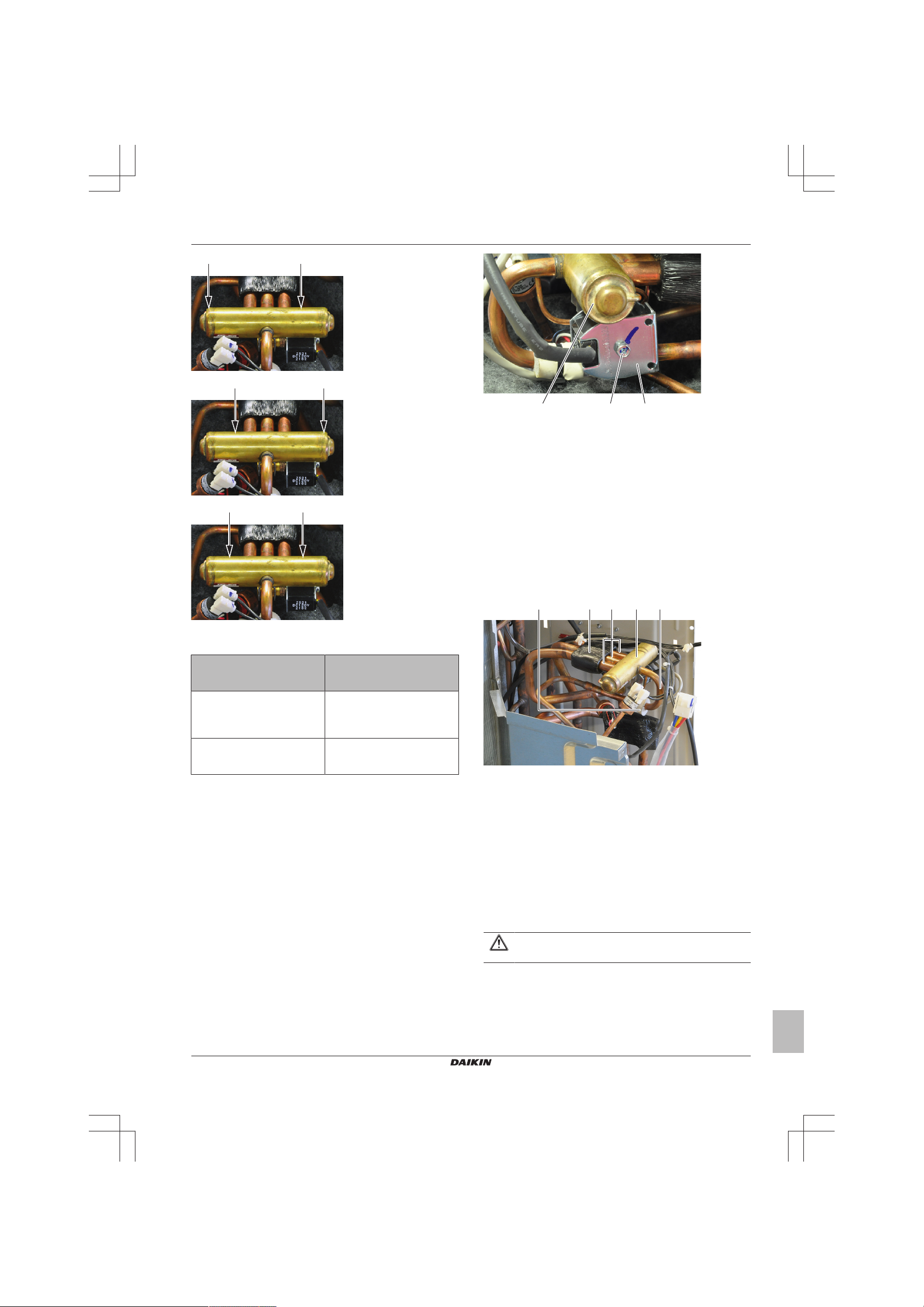
a Screw
b 4‑way valve coil
c 4‑way valve body
2 Cut all tie straps that fix the 4‑way valve coil harness.
3 Disconnect the 4‑way valve coil connector from the main PCB.
4 To install the 4‑way valve coil, see "2.1.2Repair procedures"on
page19.
To remove the 4-way valve body
Prerequisite: Recuperate the refrigerant from the refrigerant circuit,
see "3.2.2Repair procedures"on page54.
1 Remove the 4‑way valve coil from the 4‑way valve body, see
"2.1.2Repair procedures"on page19.
2 Cut the 4‑way valve pipes using a pipe cutter.
a Magnet attracted
b Magnet attracted
c Magnet NOT attracted
Magnet is attracted in the
correct positions of the 4‑way
valve?
Yes The 4‑way valve is OK. Return to
No Replace the 4‑way valve body,
Action
the troubleshooting of the
specific error and continue with
the next procedure.
see "2.1.2Repair procedures"on
page19.
2.1.2 Repair procedures
To remove the 4-way valve coil
Prerequisite: Turn OFF the unit via the user interface.
Prerequisite: Turn OFF the respective circuit breaker.
Prerequisite: Remove the required plate work, see "2.13 Plate
work"on page40.
Prerequisite: If needed, remove any parts to create more space for
the removal of the 4‑way valve coil.
1 Remove the screw and remove the 4‑way valve coil from the
4‑way valve body.
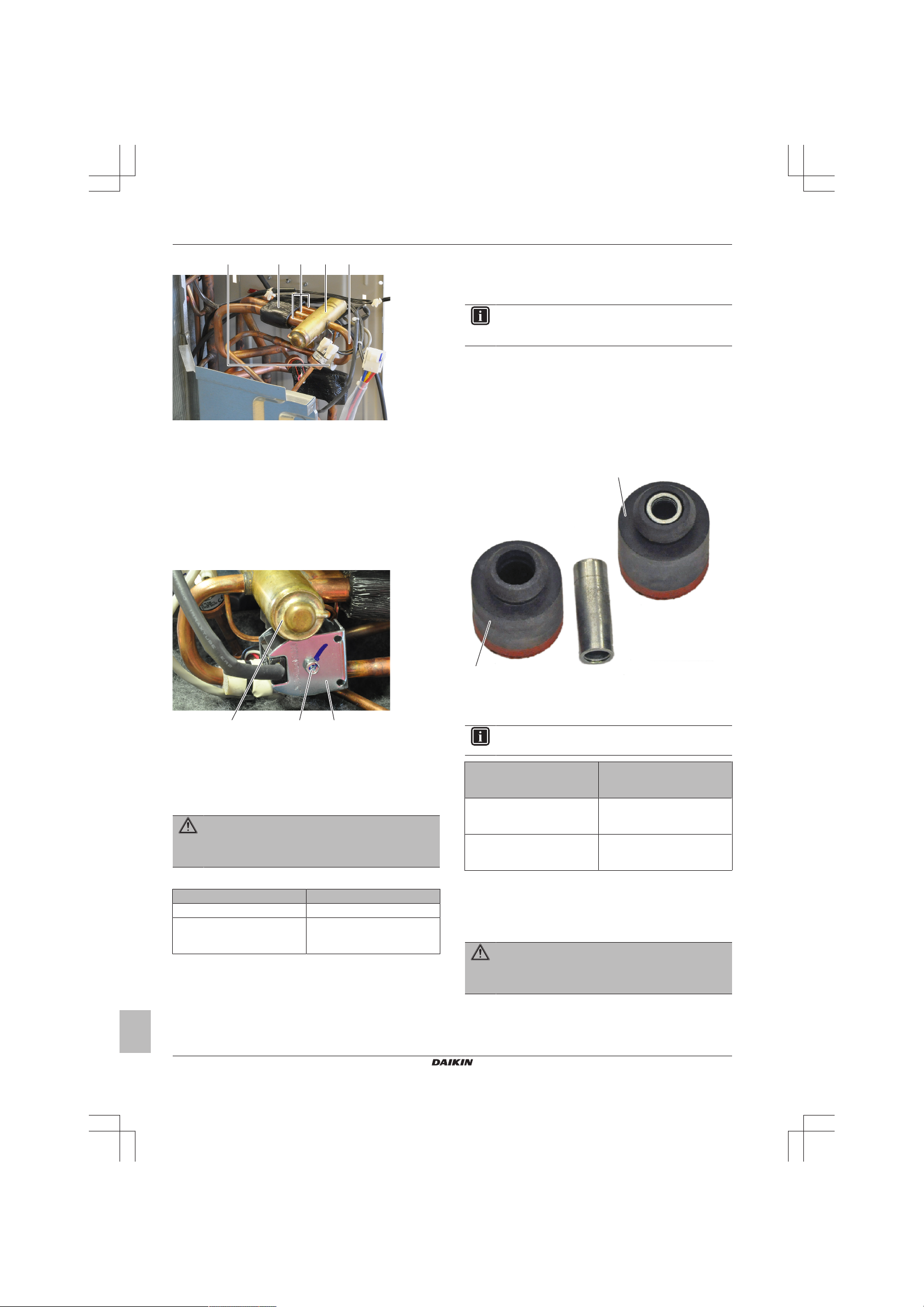
a 4‑way valve pipe
b 4‑way valve
c Putty
d Insulation
3 Remove the 4‑way valve.
4 Keep the putty and the insulation for re-use.
5 To install the 4‑way valve body, see "2.1.2 Repair
procedures"on page19.
To install the 4-way valve body
1 Install the 4‑way valve in the correct location.
2 Wrap a wet rag around the 4‑way valve and solder the 4‑way
valve pipes to the 4‑way valve.
CAUTION
Overheating the valve will damage or destroy it.
(C)(F)TXA15~50A2V1B(W)(S)(T) + RXA42+50A2V1B +
RXA20~35A2V1B
Split Stylish R32
ESIE18-03 – 2018.09
Service manual
19
2 Components
cd a b a
c a b
a
a
a 4‑way valve pipe
b 4‑way valve
c Putty
d Insulation
3 Install the putty and the insulation in their original location.
4 Install the 4‑way valve coil on the 4‑way valve body, see
"2.1.2Repair procedures"on page19.
5 Add refrigerant to the refrigerant circuit, see "3.2.2 Repair
procedures"on page54.
To install the 4-way valve coil
1 Install the 4‑way valve coil on the 4‑way valve body.
2.2 Compressor
2.2.1 Checking procedures
INFORMATION
It is recommended to perform the checks in the listed
order.
To perform a mechanical check of the compressor
Prerequisite: Turn OFF the unit via the user interface.
Prerequisite: Turn OFF the respective circuit breaker.
Prerequisite: Remove the required plate work, see "2.13 Plate
work"on page40.
1 Open the compressor insulation.
2 Check the compressor dampers and piping for any damage.
a Screw
b 4‑way valve coil
c 4‑way valve body
2 Install and tighten the screw to fix the 4‑way valve coil.
3 Route the 4‑way valve coil harness towards the main PCB.
4 Connect the 4‑way valve coil connector to the main PCB.
WARNING
When reconnecting a connector to the PCB, do NOT apply
force, as this may damage the connector or connector pins
of the PCB.
5 Fix the 4‑way valve coil harness using new tie straps.
Is the problem solved? Action
Yes No further actions required.
No Return to the troubleshooting of
the specific error and continue
with the next procedure.
a Damper
INFORMATION
The compressor dampers may look different.
Compressor dampers and
piping are in a good
condition?
Yes Perform an electrical check of the
No Replace the compressor, see
Action
compressor, see "2.2.1Checking
procedures"on page20.
"2.2.2Repair procedures"on
page22.
To perform an electrical check of the compressor
1 First perform a mechanical check of the compressor, see
"2.2.1Checking procedures"on page20.
2 Open the compressor insulation.
WARNING
The smoothing capacitor MUST discharge below 10V DC
before disconnecting the Faston connectors from the
compressor wiring terminals. Risk of electrocution.
3 Remove the cover of the compressor wire terminals.
Service manual
20
(C)(F)TXA15~50A2V1B(W)(S)(T) + RXA42+50A2V1B +
RXA20~35A2V1B
Split Stylish R32
ESIE18-03 – 2018.09
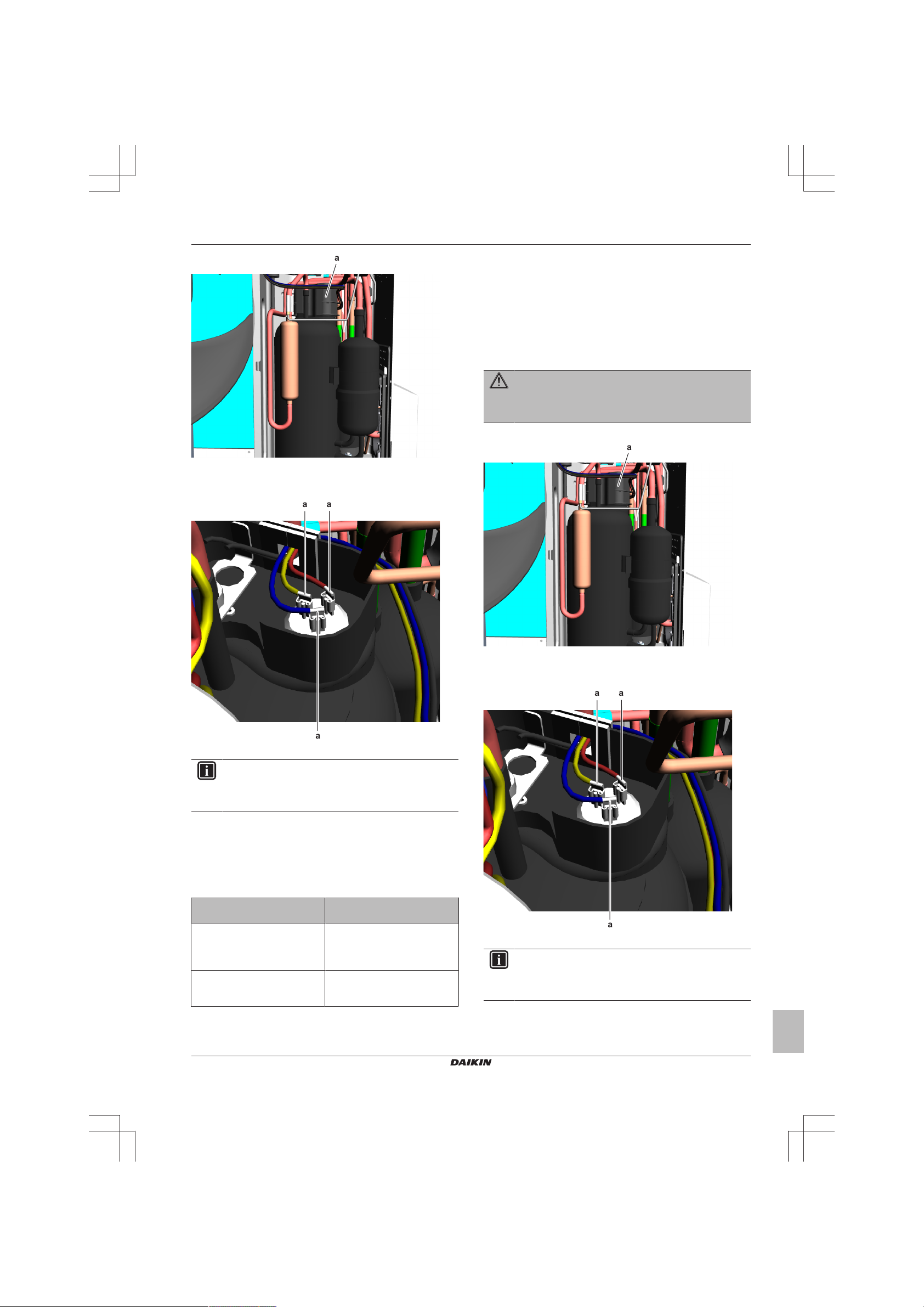
a
a Compressor wire terminals cover
a a
a
a
a a
a
4 Disconnect the Faston connectors from the compressor wire
terminals U, V and W.
2 Components
To perform an insulation check of the compressor
Prerequisite: First perform an electrical check of the compressor,
see "2.2.1Checking procedures"on page20.
Prerequisite: Turn OFF the unit via the user interface.
Prerequisite: Turn OFF the respective circuit breaker.
Prerequisite: Remove the required plate work, see "2.13 Plate
work"on page40.
1 Open the compressor insulation.
WARNING
The smoothing capacitor MUST discharge below 10V DC
before disconnecting the Faston connectors from the
compressor wiring terminals. Risk of electrocution.
2 Remove the cover of the compressor wire terminals.
a Faston connectors
INFORMATION
Note the position of the Faston connectors on the
compressor wire terminals to allow correct connection
during installation.
5 Measure the resistance between the compressor motor
windings U-V, V-W and U-W. All measurements MUST be the
same.
6 Re-connect the Faston connectors and run the compressor.
7 Measure the current in each phase U-V, V-W and U-W. All
measurements MUST be the same.
Compressor motor winding
measurements are correct?
Yes Perform an insulation check of
No Replace the compressor, see
Action
the compressor, see
"2.2.1Checking procedures"on
page20.
"2.2.2Repair procedures"on
page22.
a Compressor wire terminals cover
3 Disconnect the Faston connectors from the compressor wire
terminals U, V and W.
a Faston connectors
INFORMATION
Note the position of the Faston connectors on the
compressor wire terminals to allow correct connection
during installation.
4 Set the Megger voltage to 500VDC or 1000VDC.
5 Connect the Megger ground test lead directly to the compressor
ground wire.
(C)(F)TXA15~50A2V1B(W)(S)(T) + RXA42+50A2V1B +
RXA20~35A2V1B
Split Stylish R32
ESIE18-03 – 2018.09
Service manual
21
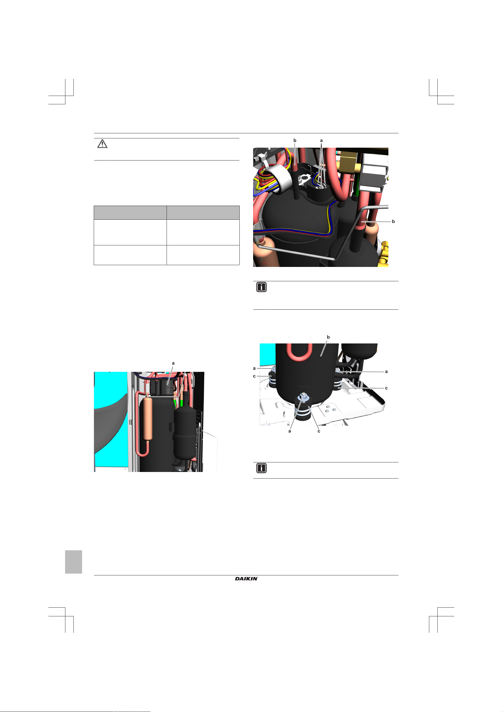
2 Components
a
ab
b
a
a
a
b
c
c
c
CAUTION
Do NOT connect the Megger ground test lead to any other
ground wire.
6 Measure the insulation resistance between the following
terminals. The measured insulation resistance MUST be
>3MΩ.
▪ U–ground,
▪ V–ground,
▪ W–ground.
Compressor insulation
measurements are correct?
Yes Perform a check of the
No Replace the compressor, see
Action
compressor overload protection,
see "2.2.1Checking
procedures"on page20..
"2.2.2Repair procedures"on
page22.
2.2.2 Repair procedures
To remove the compressor
Prerequisite: Turn OFF the unit via the user interface.
Prerequisite: Turn OFF the respective circuit breaker.
Prerequisite: Remove the required plate work, see "2.13 Plate
work"on page40.
Prerequisite: Recuperate the refrigerant from the refrigerant circuit,
see "3.2.2Repair procedures"on page54.
1 If needed, remove any parts to create more space for the
removal of the compressor.
2 Remove the cover of the compressor wire terminals.
a Faston connectors
c Compressor pipe
INFORMATION
Note the position of the Faston connectors on the
compressor wire terminals to allow correct connection
during installation.
4 Cut the compressor pipes (below the soldered joint) using a
pipe cutter.
5 Remove the 3 nuts and remove the compressor from the unit.
a Nut
b Compressor
c Damper
6 Remove the 3 dampers and springs from the compressor.
INFORMATION
a Compressor wire terminals cover
3 Disconnect the Faston connectors from the compressor wire
terminals U, V and W.
The compressor dampers may look different.
7 Remove the bushings and keep them for re-use.
8 Keep the putty for re-use.
9 To install the compressor, see "2.2.2 Repair procedures" on
page22.
To install the compressor
1 Check the state of the dampers. Replace if worn.
2 Install the 3 dampers and springs in the correct location on the
outdoor unit.
Service manual
22
(C)(F)TXA15~50A2V1B(W)(S)(T) + RXA42+50A2V1B +
RXA20~35A2V1B
Split Stylish R32
ESIE18-03 – 2018.09
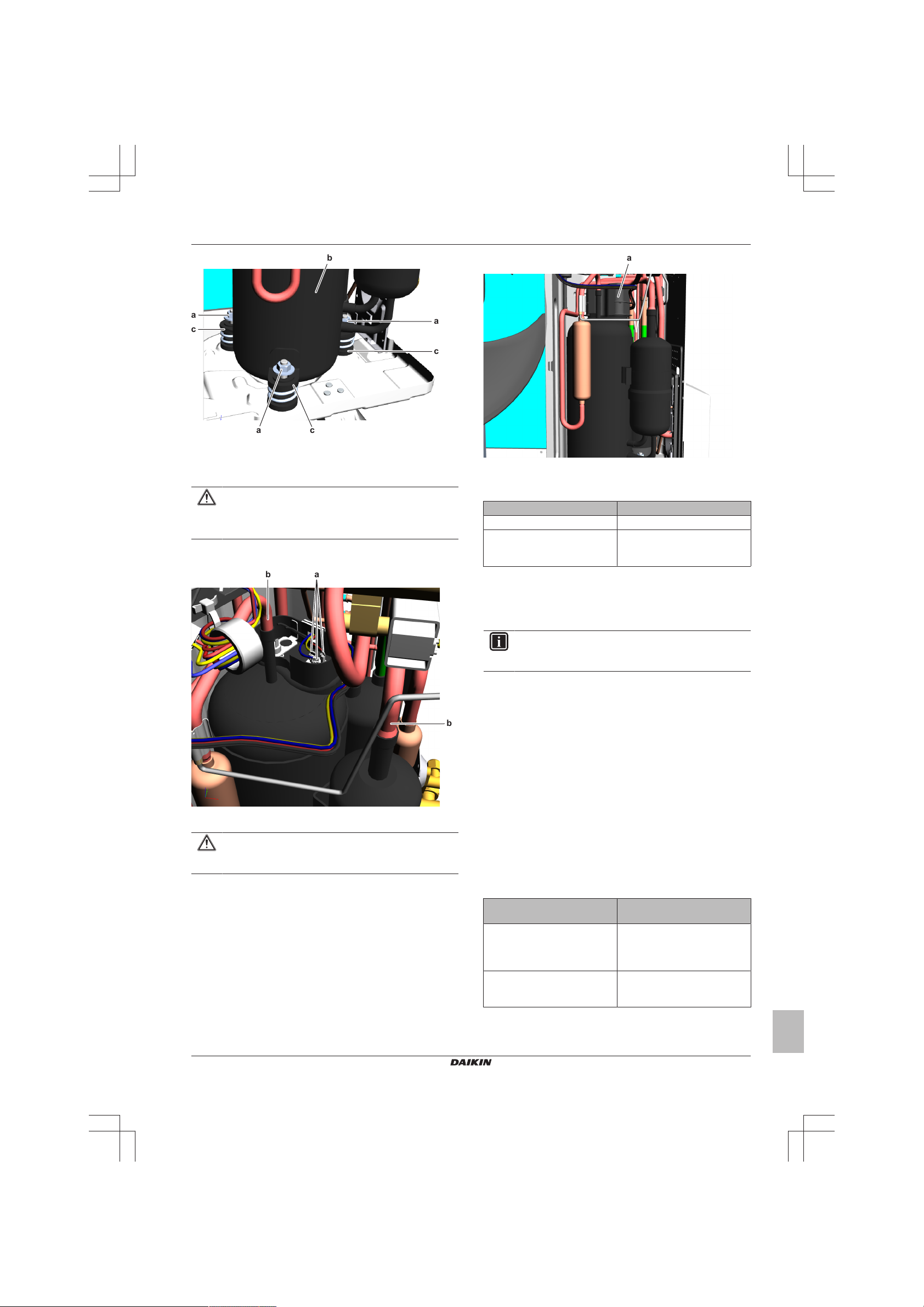
a
a
a
b
c
c
c
a Nut
ab
b
a
b Compressor
c Damper
3 Remove the caps from the compression pipe and suction pipe.
CAUTION
The oil in the compressor is hygroscopic. Therefore
remove the caps from the compressor pipes as late as
possible.
4 Wrap a wet rag around the compressor pipes and solder the
compressor pipes to the refrigerant pipes.
2 Components
a Compressor wire terminals cover
8 Add refrigerant to the refrigerant circuit, see "3.2.2 Repair
procedures"on page54.
Is the problem solved? Action
Yes No further actions required.
No Return to the troubleshooting of
the specific error and continue
with the next procedure.
a Faston connectors
c Compressor pipe
CAUTION
Overheating the compressor pipes (and the oil inside the
compressor pipes) will damage or destroy the compressor.
5 Install the putty in the correct location.
6 Connect the Faston connectors to the compressor wire
terminals U, V and W
7 Install the cover of the compressor wire terminals.
2.3 Expansion valve
2.3.1 Checking procedures
INFORMATION
It is recommended to perform the checks in the listed
order.
To perform a mechanical check of the expansion valve
Prerequisite: Power OFF the unit for 3minutes. Then turn ON the
unit and listen to the expansion valve assembly. If the expansion
valve does NOT make a latching sound, continue with the electrical
check of the expansion valve, see "2.3.1 Checking procedures"on
page23.
Prerequisite: Turn OFF the unit via the user interface.
Prerequisite: Turn OFF the respective circuit breaker.
Prerequisite: Remove the required plate work, see "2.13 Plate
work"on page40.
1 Remove the expansion valve motor from the expansion valve
body, see "2.3.2Repair procedures"on page24.
2 Slide the magnet (tool part number 9950038) over the
expansion valve body and gently rotate the magnet clockwise/
counterclockwise to manually close/open the expansion valve
body.
Does the expansion valve
body open?
Yes Perform an electrical check of the
No Replace the expansion valve
Action
expansion valve, see
"2.3.1Checking procedures"on
page23.
body, see "2.3.2Repair
procedures"on page24.
(C)(F)TXA15~50A2V1B(W)(S)(T) + RXA42+50A2V1B +
RXA20~35A2V1B
Split Stylish R32
ESIE18-03 – 2018.09
Service manual
23
 Loading...