

Daikin FTXN18KVJU, FTX50KVM, FTKN60KVM, FTX60KVM, FT15LV2S Service Manual
...
REMOVAL
PROCEDURE
SERVICE MANUAL
Indoor Unit
Inverter / Non-Inverter
Wall Mounted Type
5.0/6.0/7.1 kW Class
15000/18000/24000 Btu/h Class
Si041142

Service Manual
Removal Procedure
Indoor Unit
Applicable Models
zCooling Only zHeat Pump
FTXN15KVJU FTXN15KVJU
FTXN18KVJU FTXN18KVJU
FTXN24KVJU FTXN24KVJU
FTKN50KVM FTX50KVM
FTKN60KVM FTX60KVM
FT15LV2S FTXS50KVM
FT18LV2S FTXS60KVM
FTXS71KVM
FT50HV1
FT60HV1
FT50HV14
FT60HV14
FT60HV16
FT50JV1V
FT50MV16
FTE50KV1
FTE60KV1
FTE50KV14
FTE60KV14
FTE50LV1V
FTE60LV1V
FTE50LV16
FTE60LV16
FTE50LV169
FTE60LV169
FTE50MV16
FTE60MV16
FTN50HV1G
FTN60HV1G

Si041142
Removal Procedure 1
Table of Contents
1. Removal of Air Filters / Front Panel ........................................................2
2. Removal of Front Grille ...........................................................................5
3. Removal of Horizontal Blades / Vertical Blades......................................7
4. Removal of Electrical Box / PCBs / Swing Motors ..................................9
5. Removal of Indoor Heat Exchanger ......................................................15
6. Removal of Fan Motor / Fan Rotor........................................................18
Note:
The illustrations may be slightly different depending on the model.

Removal of Air Filters / Front Panel Si041142
2 Removal Procedure
1. Removal of Air Filters / Front Panel
Procedure Warning Be sure to wait for 10 minutes or more after turning off all power
supplies before disassembling work.
Step Procedure Points
1. Appearance features
Warning
Dangerous: High voltage
A high voltage is applied to all
the electric circuits of this
product including
thermistors.
When the signal receiver
catches a signal from the
remote controller, the
receiving tone sounds and
the operation lamp blinks
immediately to confirm the
signal reception.
When the [ON/OFF] button
is kept pressed for 5
seconds, the forced cooling
operation is performed for
about 15 minutes.
Some models have no
HOME LEAVE lamp.
2. Remove the air filters.
1
Open the front panel to
the position where it
stops.
2
3
Slightly push up the
center knob of the air
filter and unfasten the
hooks.
Pull out the air filter
downward and remove
it.
The air filter is not marked
for difference between the
right and left sides.
Insert the air filter with the
"FRONT" mark faced up.
The air filter can be set
easily by inserting it along
the guides.
Be sure to insert the hooks
(at 2 lower positions) when
mounting the air filter.
(R12786)
Operation lamp
Signal receiver
TIMER lamp
[ON/OFF] button
(R17229)
Room temperature thermistor
HOME LEAVE
lamp
(R6701)
Front panel
Air filter
(R6702)
Si041142 Removal of Air Filters / Front Panel
Removal Procedure 3
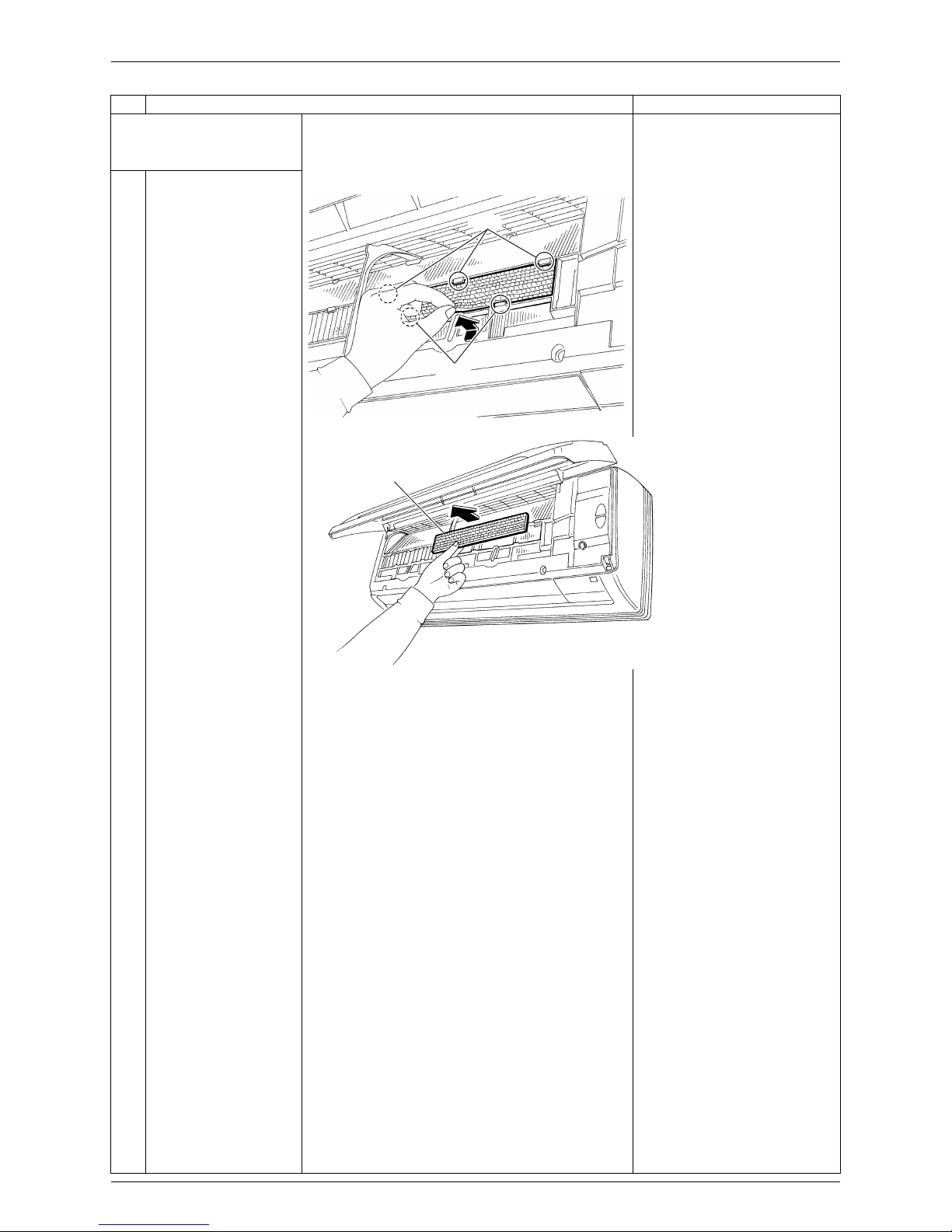
3. Remove the Titanium
apatite photocatalytic airpurifying filters.
The right and left filters are
interchangeable.
Some models have no
Titanium apatite
photocatalytic air-purifying
filter.
Some models have Airpurifying filters with
photocatalytic deodorizing
function instead.
Some models have air filters
only.
1
Push up the bottom of
the Titanium apatite
photocatalytic airpurifying filter to
unfasten the hooks (2
on lower, 3 on upper)
and take the filter out.
Step Procedure Points
Hook
Hook
(R2751)
Titanium apatite
photocatalytic airpurifying filter
(R12788)

Removal of Air Filters / Front Panel Si041142
4 Removal Procedure
4. Remove the front panel.
1
While opening the front
panel further than it
stops, release both the
shafts and remove the
front panel.
Slide the front panel from
side to side to release each
shaft.
When reassembling the front
panel, fit the right and left
rotary shafts one by one into
the grooves and fully push
them into position.
Step Procedure Points
(R2753)
(R2754)
(R2755)
Si041142 Removal of Front Grille
Removal Procedure 5
2. Removal of Front Grille
Procedure Warning Be sure to wait for 10 minutes or more after turning off all power
supplies before disassembling work.
Step Procedure Points
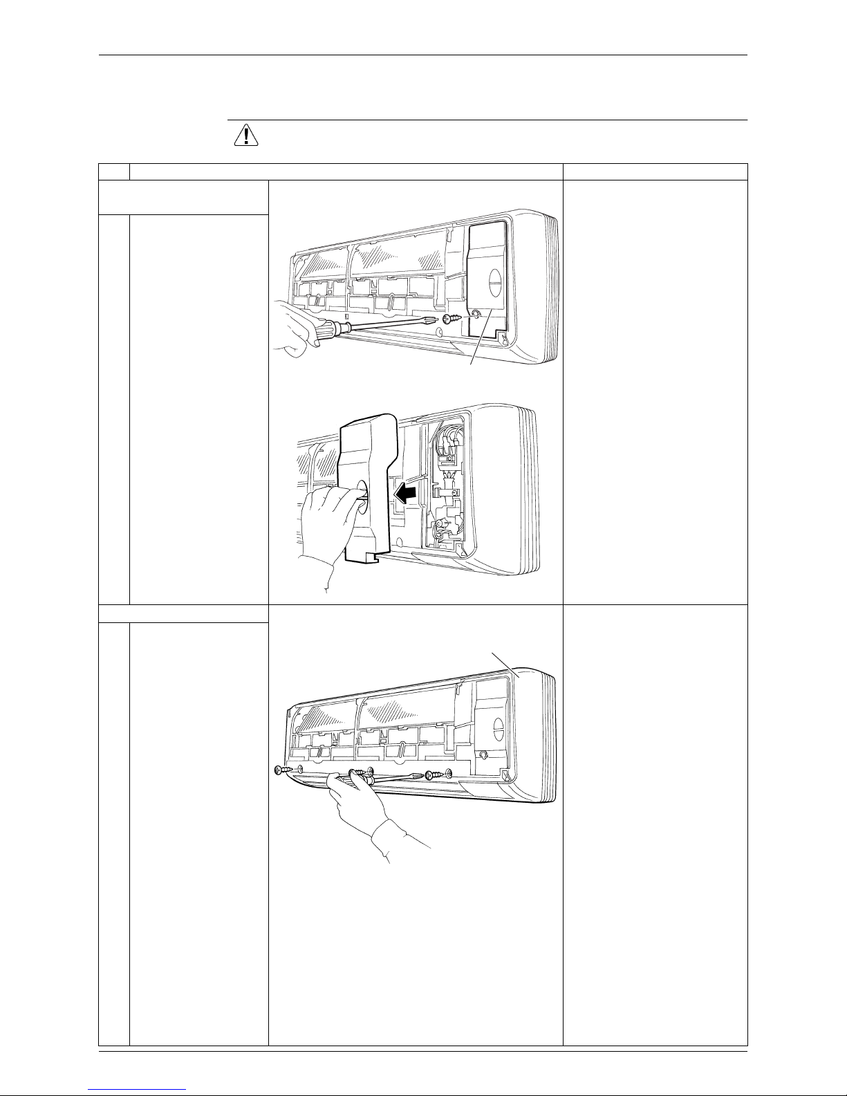
1. Remove the service
cover.
Preparation
Remove the front panel
according to "Removal of the
Air Filters / Front Panel".
You can remove the front
grille without detaching the
service cover.
1
Remove the screw and
remove the service
cover.
2. Remove the front grille.
1
Remove the 3 screws
of the front grille.
Refer to the removal
procedure in a reverse way
when reassembling.
Service cover
(R2756)
(R2757)
(R2758)
Front grille
 Loading...