

Daikin FFRN50CXV1, FCRN100EXV1, FFRN35CXV1, FCRN71EXV1, FCRN125EXV1 Technical Manual
...
TECHNICAL MANUAL
Split Unit Air Conditioner
Ceiling Cassette C & E Series
FCQN-E, FFQN-C, FCRN-E, FFRN-C
— Cooling only & Heatpump [50Hz] —
R410A
DAIKIN_FFRN.indb iDAIKIN_FFRN.indb i 12/27/2012 9:28:06 AM12/27/2012 9:28:06 AM

DAIKIN_FFRN.indb iiDAIKIN_FFRN.indb ii 12/27/2012 9:28:07 AM12/27/2012 9:28:07 AM

Table of Contents
Table of Contents
Nomenclature......................................................................................................................1
Indoor ............................................................................................................................1
Outdoor ..........................................................................................................................1
Product Line-Up .............................................................................................................2
Application Information .....................................................................................................5
Operating Range ...........................................................................................................5
Refrigerant Circuit Diagrams (C Series) ........................................................................6
Refrigerant Circuit Diagrams (E Series) ........................................................................ 8
Installation Guideline ................................................................................................... 11
Sound Data ........................................................................................................................16
Sound Pressure Level ................................................................................................. 16
NC Curve ..................................................................................................................... 17
Engineering & Physical Data ...........................................................................................21
Performance Data .............................................................................................................26
Calculation Steps .........................................................................................................26
Performance Tables .....................................................................................................28
Outline & Dimension ........................................................................................................50
Wiring Diagram .................................................................................................................53
Service & Maintenance ....................................................................................................64
Troubleshooting ...............................................................................................................66
DAIKIN_FFRN.indb iiiDAIKIN_FFRN.indb iii 12/27/2012 9:28:07 AM12/27/2012 9:28:07 AM
Nomenclature
1
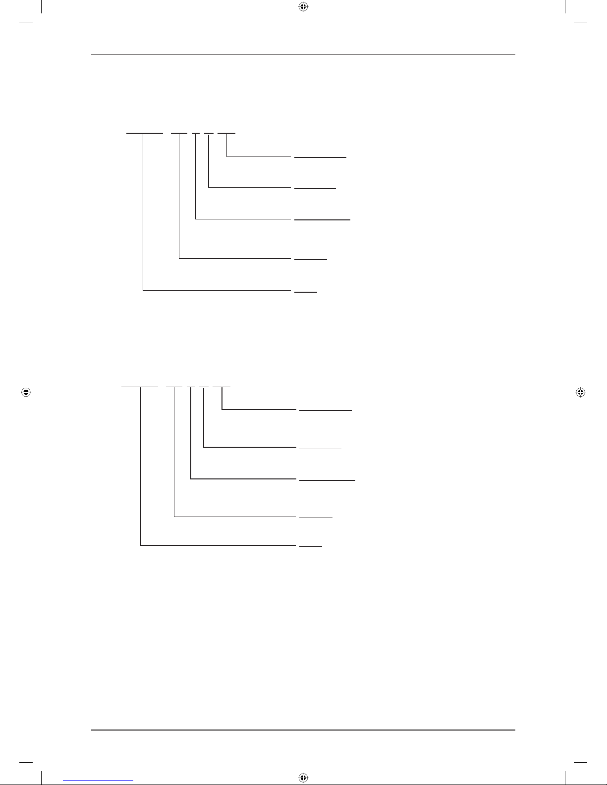
Nomenclature
Indoor
FFRN 25 C X V1
Power Supply
V1: 1 phase 50 Hz 220-240V
Production
X: OYLM
Product Series
C: C Series
E: E Series
Capacity
25: 2.5 kW
Model
FFRN: Ceiling Cassette 2”x2” (Cooling Only)
FCRN: Ceiling Cassette 3”x3” (Cooling Only)
FFQN: Ceiling Cassette 2”x2” (Heatpump)
FCQN: Ceiling Cassette 3”x3” (Heatpump)
Outdoor
R(Y)N 25 C X V1
Power Supply
V1: 1 phase 50 Hz 220-240V
Y1: 3 phase 50 Hz 380-415V
Production
X: OYLM
Product Series
C: C Series
D: D Series
Capacity
25: 2.5 kW
Model
RR & RN: Single Split Condensing Unit (Cooling
Only)
RYN & RQ: Single Split Condensing Unit (Heatpump)
DAIKIN_FFRN.indb 1DAIKIN_FFRN.indb 1 12/27/2012 9:28:07 AM12/27/2012 9:28:07 AM

Nomenclature
2
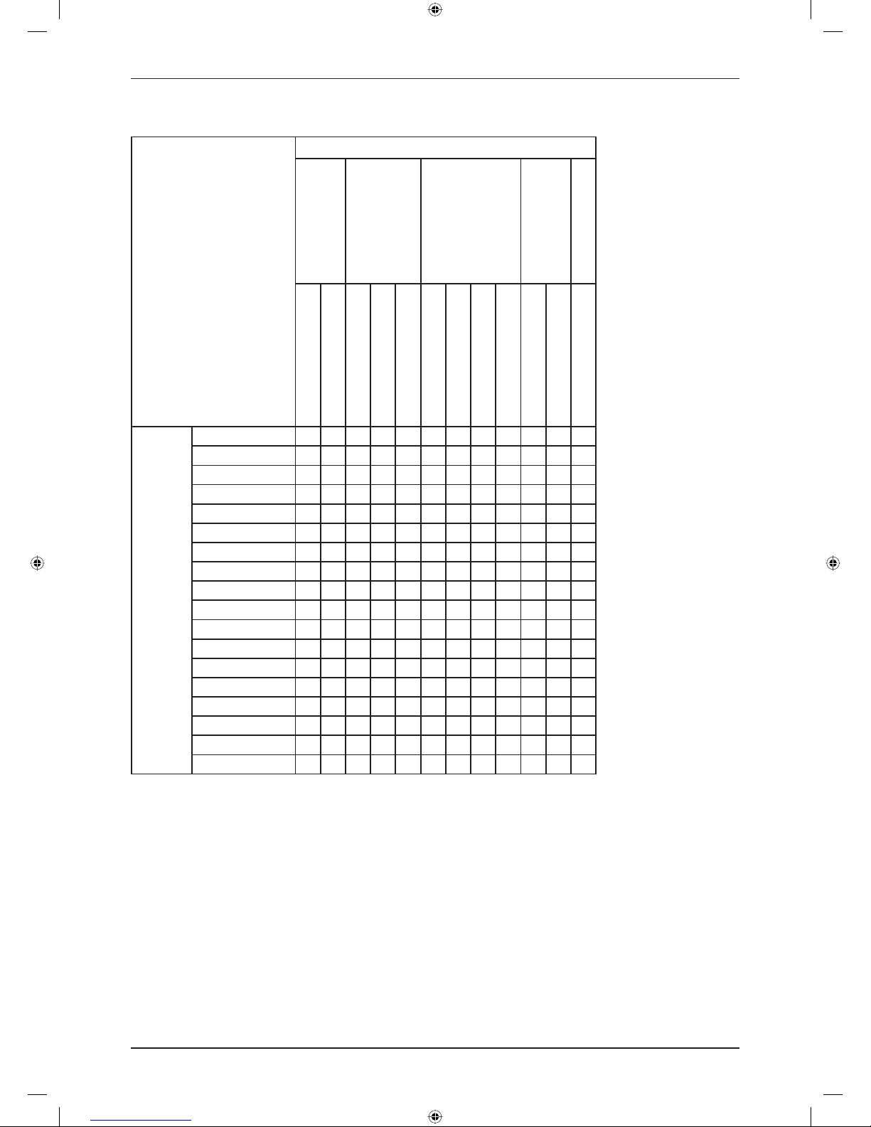
Product Line-Up
Indoor Unit
FCQN-E, FFQN-C, FCRN-E, FFRN-C
Nomenclature
Classifi cation
Panel (Handset)
PCB
Fin
Refrigerant Control
BC20CXW (BRC52A62)
BYC20CXW (BRC52A61)
BC50EXW (BRC52A62)
BYC50EXW (BRC52A61)
L208A EC
L208A AP
L2CKE EC
L2CKE AP
Hydrophilic (Blue)
Cap Tube
w/o Cap Tube
COOLING
FFRN25CXV1 X X X X
FFRN35CXV1 X X X X
FFRN50CXV1 X X X X
FCRN50EXV1 X X X X
FCRN60EXV1 X X X X
FCRN71EXV1 X X X X
FCRN100EXV1 X X X X
FCRN125EXV1 X X X X
HEATPUMP
FFQN25CXV1 X X X X
FFQN35CXV1 X X X X
FFQN50CXV1 X X X X
FCQN50EXV1 X X X X
FCQN60EXV1 X X X X
FCQN71EXV1 X X X X
FCQN100EXV1 X X X X
FCQN125EXV1 X X X X
DAIKIN_FFRN.indb 2DAIKIN_FFRN.indb 2 12/27/2012 9:28:07 AM12/27/2012 9:28:07 AM
Nomenclature
3
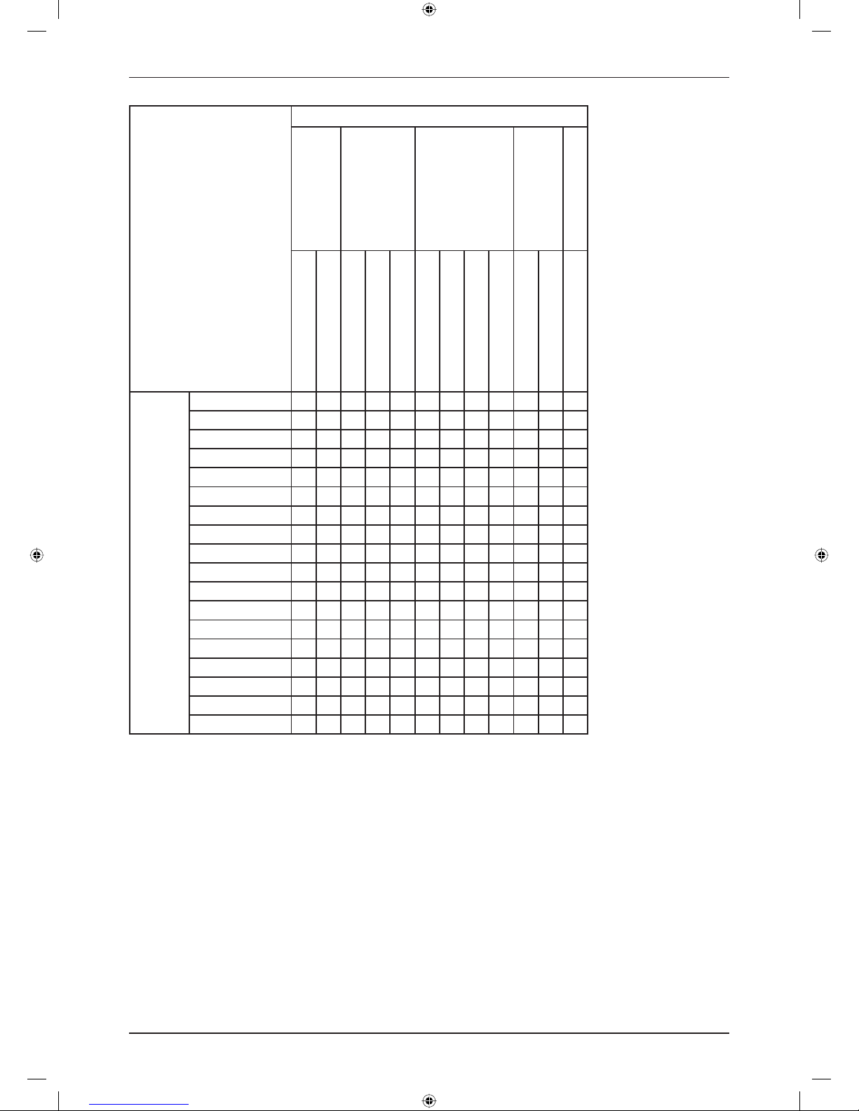
Outdoor Unit
R(Y)N / RR / RQ
Nomenclature
Classifi cation
Refrigerant Control
Fin
Safety Devices
Compressor
Others
Cap Tube
TXV
Hydrophilic (Blue)
Hydrophilic (Gold)
Bare Aluminium
Contactor
High Pressure Switch
Low Pressure Switch
Phase Sequencer
Scroll
Rotary
Drain Elbow
COOLING
RN25CXV1 X X X
RN25CGXV1 X X X
RN35CXV1 X X X
RN35CGXV1 X X X
RN50CXV1 X X X
RN50CGXV1 X X X
RN60CXV1 X X X
RN60CGXV1 X X X
RR71CXV1 X X X
RR71CGXV1 X X X
RR90DXV1 X X X X X
RR90DGXV1 X X X X X
RR100DXV1 X X X X X
RR100DGXV1 X X X X X
RR100DXY1 X X X X X X X
RR100DGXY1 X X X X X X X
RR125DXY1 X X X X X X X
RR125DGXY1 X X X X X X X
DAIKIN_FFRN.indb 3DAIKIN_FFRN.indb 3 12/27/2012 9:28:07 AM12/27/2012 9:28:07 AM
Nomenclature
4
Nomenclature
Classifi cation
Refrigerant Control
Fin
Safety Devices
Compressor
Others
Cap Tube
TXV
Hydrophilic (Blue)
Hydrophilic (Gold)
Bare Aluminium
Contactor
High Pressure Switch
Low Pressure Switch
Phase Sequencer
Scroll
Rotary
Drain Elbow
HEATPUMP
RYN25CXV1 X X X X
RYN25CGXV1 X X X X
RYN35CXV1 X X X X
RYN35CGXV1 X X X X
RYN50CXV1 X X X X
RYN50CGXV1 X X X X
RYN60CXV1 X X X X
RYN60CGXV1 X X X X
RQ71CXV1 X X X X
RQ71CGXV1 X X X X
RQ90DXV1 X X X X X X
RQ90DGXV1 X X X X X X
RQ100DXV1 X X X X X X
RQ100DGXV1 X X X X X X
RQ100DXY1 X X X X X X X X
RQ100DGXY1 X X X X X X X X
RQ125DXY1 X X X X X X X X
RQ125DGXY1 X X X X X X X X
DAIKIN_FFRN.indb 4DAIKIN_FFRN.indb 4 12/27/2012 9:28:08 AM12/27/2012 9:28:08 AM
5
Application Information
Application Information
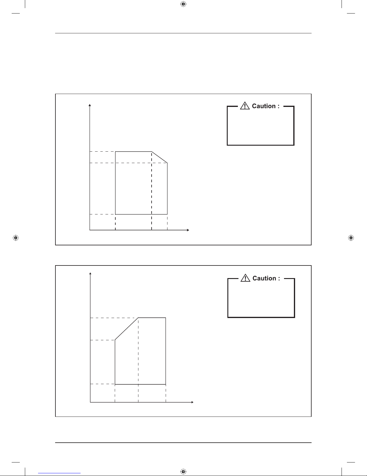
Operating Range
Ensure the operating temperature is in allowance range.
Cooling
The use of your air conditioner
outside the range of working
temperature and humidity can
result in serious failure.
Outdoor
DB (°C)
46
43
19
14 19 23 Indoor WB (°C)
Heating
The use of your air conditioner
outside the range of working
temperature and humidity can
result in serious failure.
Outdoor
WB (°C)
18
15 20 27 Indoor DB (°C)
10
-9
DAIKIN_FFRN.indb 5DAIKIN_FFRN.indb 5 12/27/2012 9:28:08 AM12/27/2012 9:28:08 AM

6
Application Information
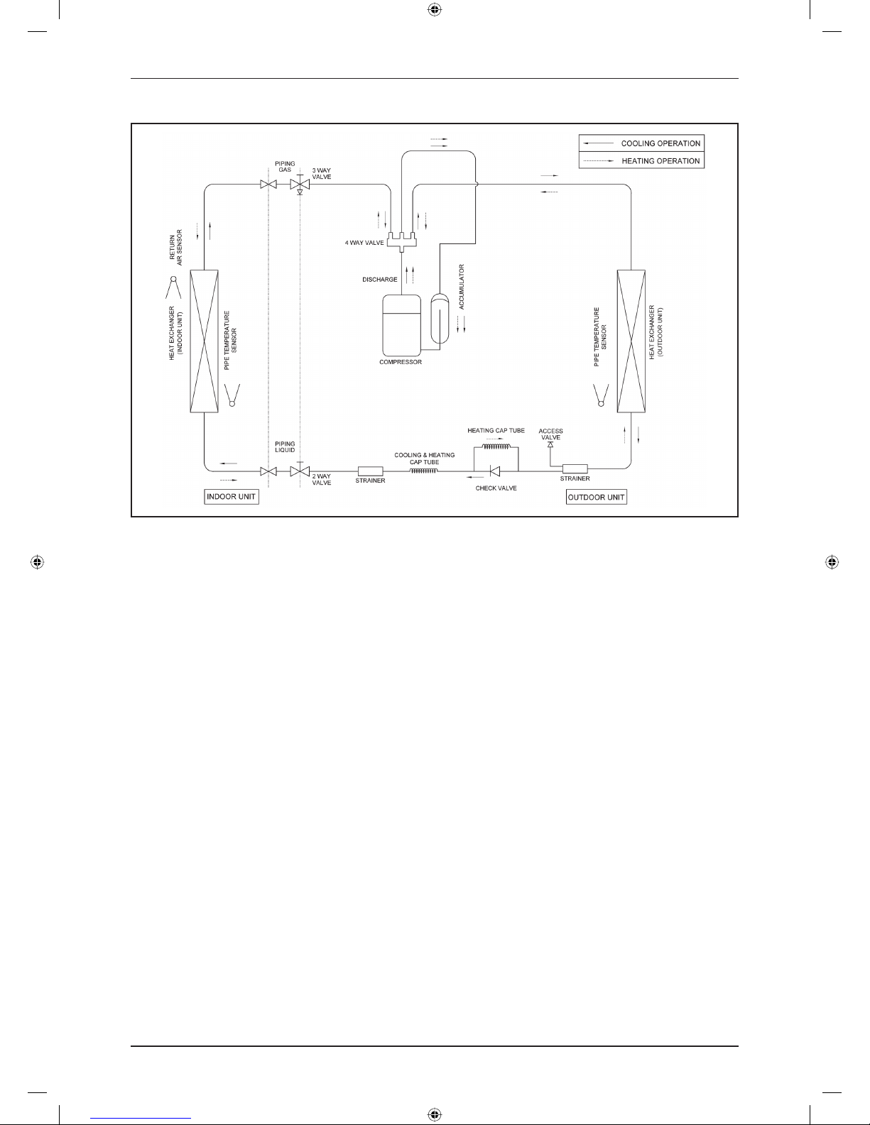
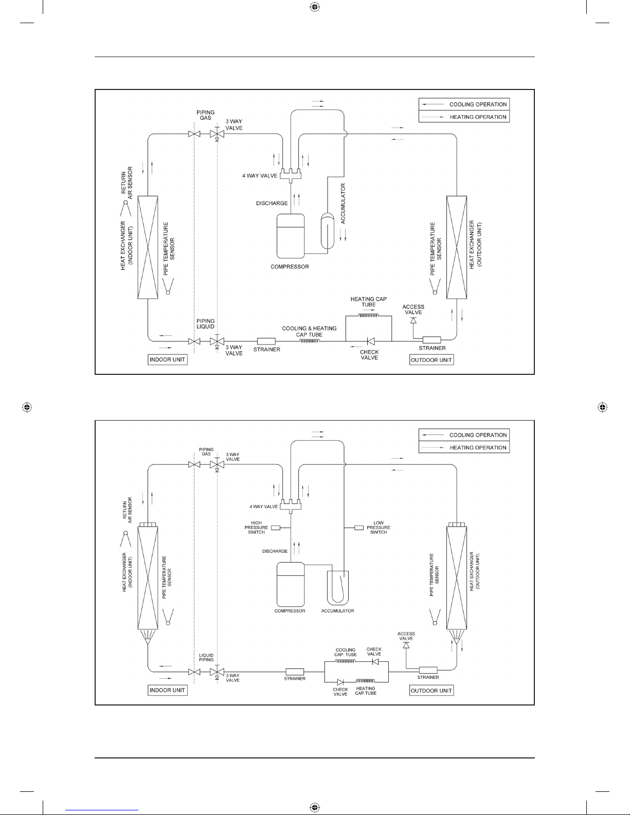
Refrigerant Circuit Diagrams (C Series)
Model: FFRN25CXV1 – RN25CXV1 / FFRN35CXV1 – RN35CXV1 / FFRN50CXV1 – RN50CXV1
Model: FFQN25CXV1 – RYN25CXV1
DAIKIN_FFRN.indb 6DAIKIN_FFRN.indb 6 12/27/2012 9:28:08 AM12/27/2012 9:28:08 AM
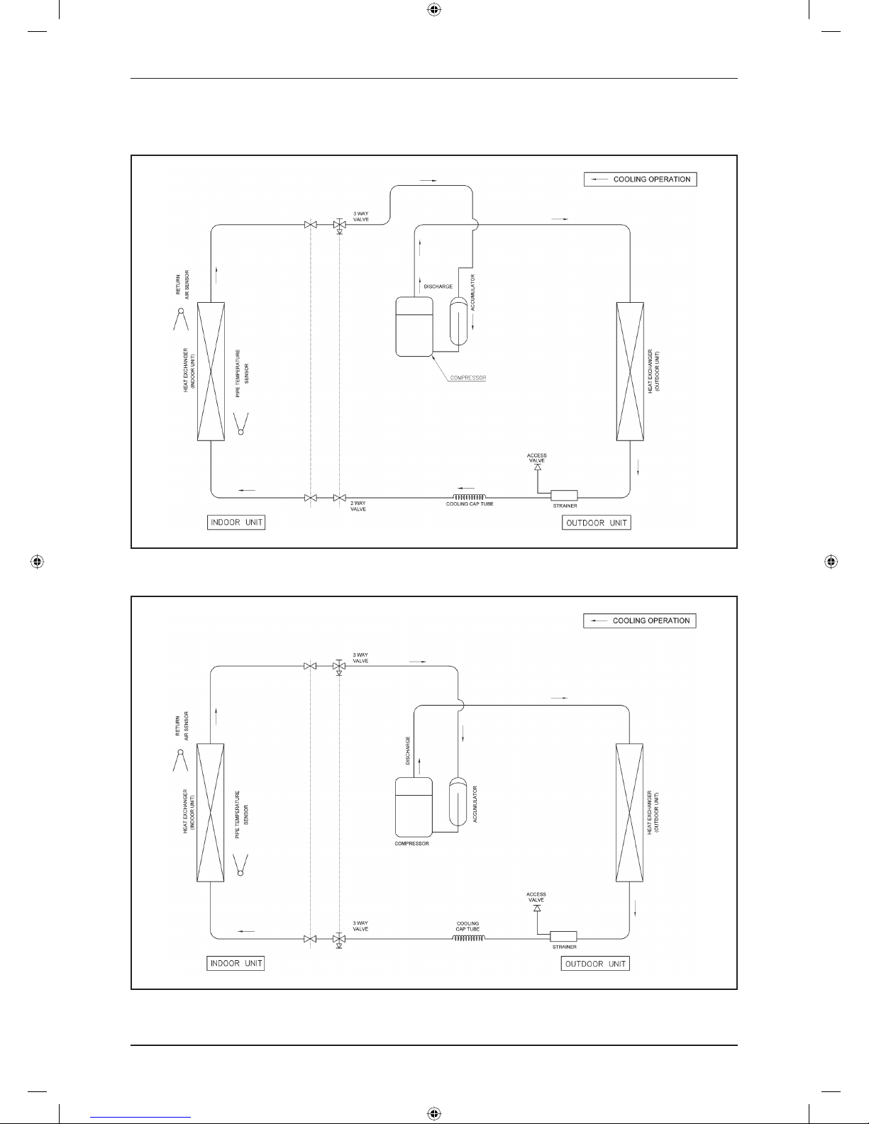
7
Application Information
Model: FFQN35CXV1 – RYN35CXV1 / FFQN50CXV1 – RYN50CXV1
DAIKIN_FFRN.indb 7DAIKIN_FFRN.indb 7 12/27/2012 9:28:08 AM12/27/2012 9:28:08 AM
8
Application Information
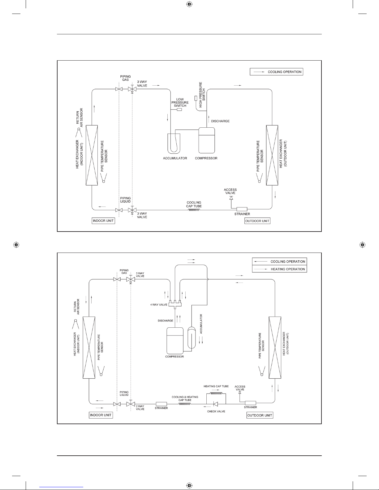
Refrigerant Circuit Diagrams (E Series)
Model: FCRN50EXV1 – RN50CXV1 / FCRN60EXV1 – RN60CXV1
Model: FCRN71EXV1 – RR71CXV1
DAIKIN_FFRN.indb 8DAIKIN_FFRN.indb 8 12/27/2012 9:28:08 AM12/27/2012 9:28:08 AM
9
Application Information
Model: FCRN100EXV1 – RR90DXV1 / FCRN100EXV1 – RR100DXV1 / FCRN100EXV1 – RR100DXY1 /
FCRN125EXV1 – RR125DXY1
Model: FCQN50EXV1 – RYN50CXV1 / FCQN60EXV1 – RYN60CXV1
DAIKIN_FFRN.indb 9DAIKIN_FFRN.indb 9 12/27/2012 9:28:08 AM12/27/2012 9:28:08 AM
10
Application Information
Model: FCQN71EXV1 – RQ71CXV1
Model: FCQN100EXV1 – RQ90DXV1 / FCQN100EXV1 – RQ100DXV1 / FCQN100EXV1 – RR100DXY1 /
FCQN125EXV1 – RR125DXY1
DAIKIN_FFRN.indb 10DAIKIN_FFRN.indb 10 12/27/2012 9:28:08 AM12/27/2012 9:28:08 AM
11
Application Information
Installation Guideline
Safety Precautions
Installation and maintenance should be performed
by qualifi ed persons who are familiar with local code
and regulation, and experienced with this type of
appliance.
All fi eld wiring must be installed in accordance with
the national wiring regulation.
Ensure that the rated voltage of the unit corresponds
to that of the name plate before commencing wiring
work according to the wiring diagram.
The unit must be GROUNDED to prevent possible
hazard due to insulation failure.
All electrical wiring must not touch the refrigerant
piping or any moving parts of the fan motors.
Confi rm that the unit has been switched OFF before
installing or servicing the unit.
Disconnect from the main power supply before
servicing the air conditioner unit.
DO NOT pull out the power cord when the power is
ON. This may cause serious electrical shocks which
may result in fi re hazards.
Keep the indoor and outdoor units, power cable and
transmission wiring, at least 1m from TVs and radios,
to prevent distorted pictures and static. {Depending
on the type and source of the electrical waves, static
may be heard even when more than 1m away}.
•
•
•
•
•
•
•
•
•
Please take note of the following important points
when installing.
Do not install the unit where leakage of fl ammable
gas may occur.
If gas leaks and accumulates around the unit, it
may cause fi re ignition.
Ensure that drainage piping is connected properly.
If the drainage piping is not connected properly,
it may cause water leakage which will dampen
the furniture.
Do not overcharge the unit.
This unit is factory pre-charged. Overcharge will
cause over-current or damage to the compressor.
Ensure that the unit’s panel is closed after service
or installation.
Unsecured panels will cause the unit to operate
noisily.
Sharp edges and coil surfaces are potential
locations which may cause injury hazards. Avoid
from being in contact with these places.
Before turning off the power supply, set the remote
controller’s ON/OFF switch to the “OFF” position
to prevent the nuisance tripping of the unit. If this is
not done, the unit’s fans will start turning automatically
when power resumes, posing a hazard to service
personnel or the user.
Do not operate any heating apparatus too close to the
air conditioner unit. This may cause the plastic panel to
melt or deform as a result of the excessive heat.
Ensure the color of wires of the outdoor unit and
the terminal markings are same to the indoors
respectively.
IMPORTANT : DO NOT INSTALL OR USE THE AIR
CONDITIONER UNIT IN A LAUNDRY ROOM.
Do not use joined and twisted wires for incoming
power supply.
•
•
•
•
•
•
•
•
•
•
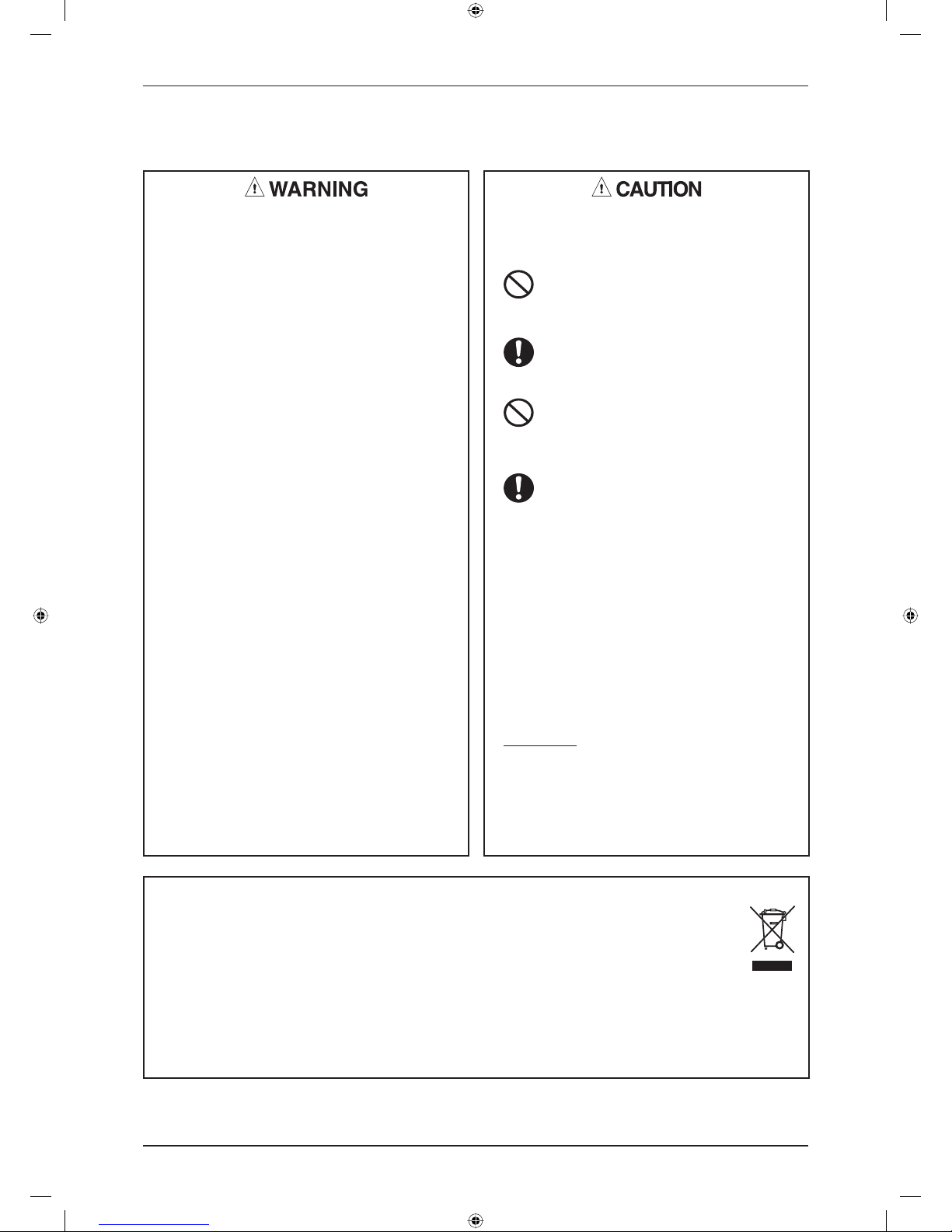
NOTICE
Disposal requirements
Your air conditioning product is marked with this symbol. This means that electrical and electronic products
shall not be mixed with unsorted household waste.
Do not try to dismantle the system yourself: the dismantling of the air conditioning system, treatment of the
refrigerant, of oil and of other parts must be done by a qualifi ed installer in accordance with relevant local and
national legislation. Air conditioners must be treated at a specialized treatment facility for re-use, recycling
and recovery. By ensuring this product is disposed of correctly, you will help to prevent potential negative
consequences for the environment and human health. Please contact the installer or local authority for more
information.
Batteries must be removed from the remote controller and disposed of separately in accordance with relevant
local and national legislation.
DAIKIN_FFRN.indb 11DAIKIN_FFRN.indb 11 12/27/2012 9:28:08 AM12/27/2012 9:28:08 AM
12
Application Information
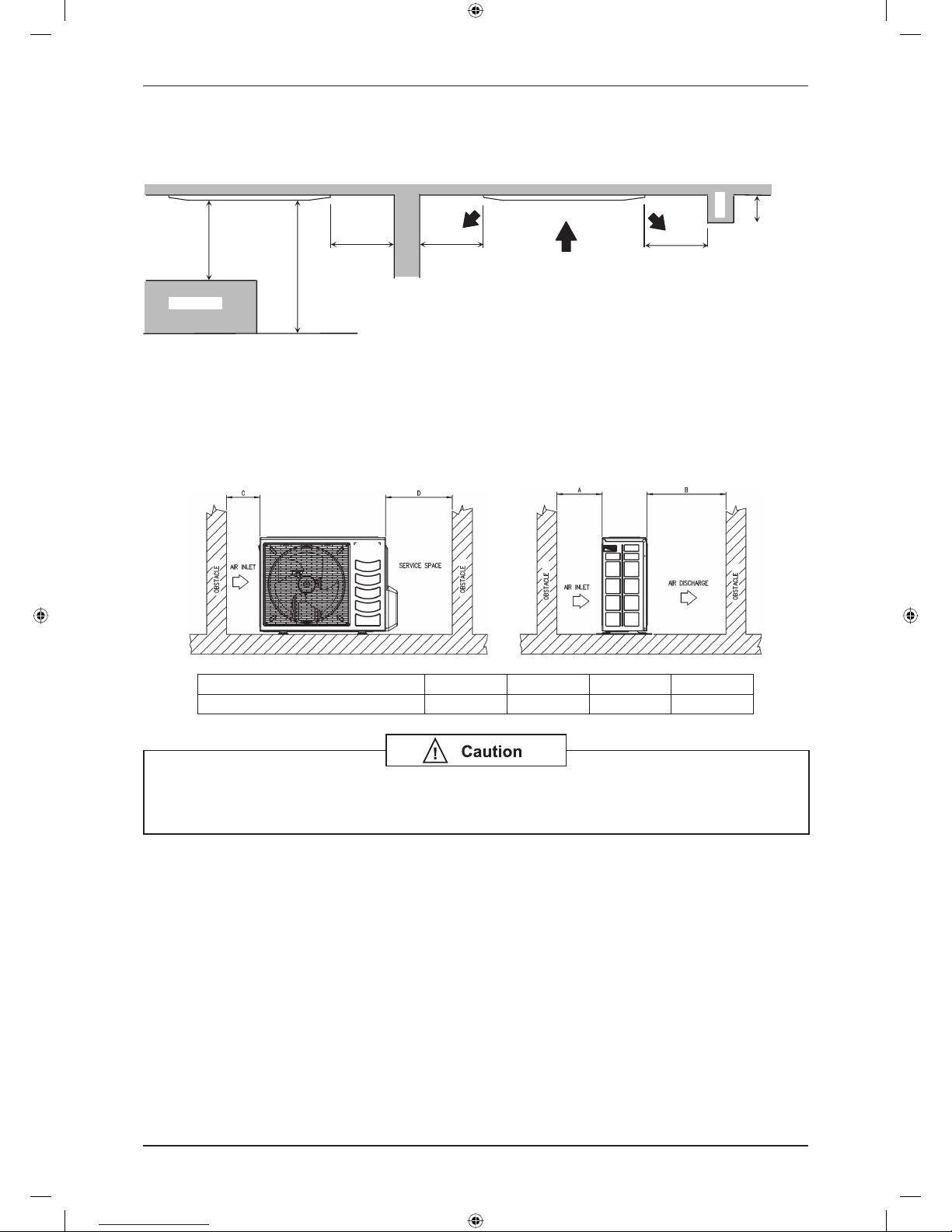
1) Indoor Installation Clearance
Clearance must be provided for the indoor unit from wall and obstacles as shown in fi gure below.
Beam
Max. 0.3 m
Min 0.5 m
Min 0.5 m
Max. 3.0 m
Min 0.5 m
Floor
Obstacles
The installation place (handling ceiling surface) must be level and the height in the ceiling is 350mm or more.
2) Outdoor Installation Clearance
Outdoor unit must be installed such that there is no short circuit of the hot discharge air or obstruction to smooth
air fl ow. Select the coolest possible place where intake air should not hotter than the outside temperature
(Max. 45°C).
ALL MODELS A B C D
Minimum Distance 300 mm 1000 mm 300 mm 500 mm
If the condensing unit is operated in an atmosphere containing oils (including machine
oils), salt (coastal area), sulphide gas (near hot spring, oil refi nery plant), such substances
may lead to failure the unit.
DAIKIN_FFRN.indb 12DAIKIN_FFRN.indb 12 12/27/2012 9:28:09 AM12/27/2012 9:28:09 AM
13
Application Information
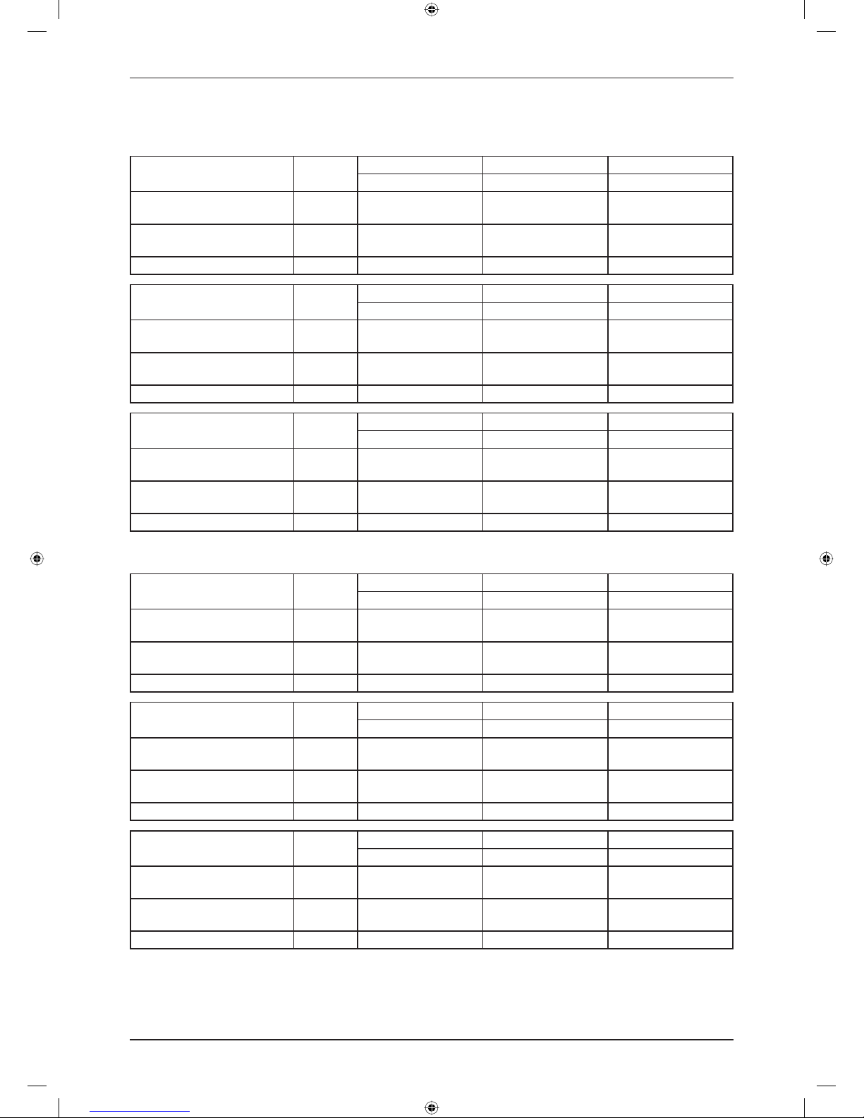
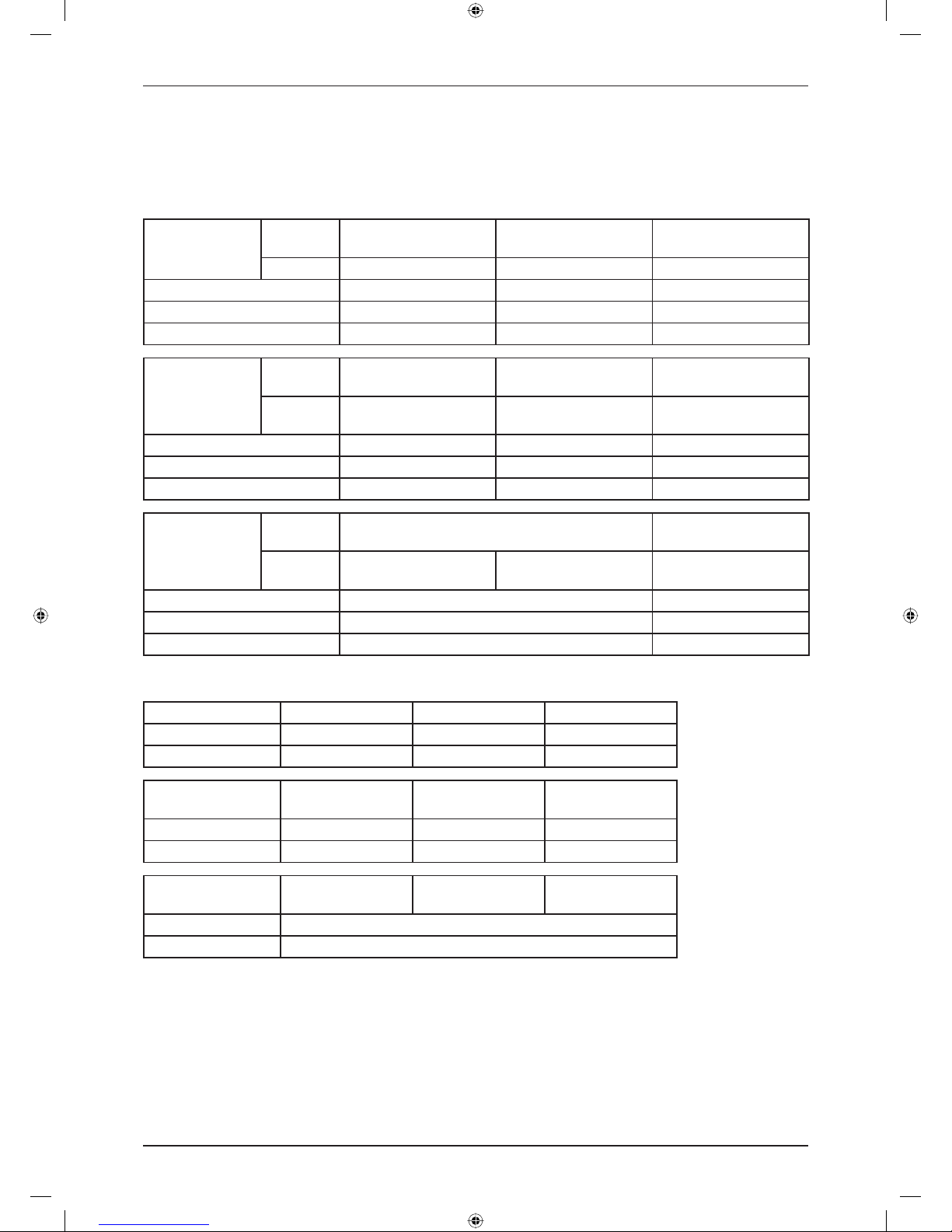
3) Cable Size
Cooling only
Model Unit
FFRN25/35CXV1 FFRN50CXV1 FCRN50EXV1
RN25/35CXV1 RN50CXV1 RN50CXV1
Power supply cable size
Number of wire
mm²
1.5
3
2.5
3
2.5
3
Interconnection cable size
Number of wire
mm²
1.5
3
2.5
3
2.5
3
Recommended fuse A 15 20 13
Model Unit
FCRN60EXV1 FCRN71EXV1 FCRN100EXV1
RN60CXV1 RR71CXV1 RR90DXV1
Power supply cable size
Number of wire
mm
2
2.5
3
4.0
3
4.0
3
Interconnection cable size
Number of wire
mm
2
2.5
3
2.5
3
2.5
4
Recommended fuse A 18 25 25
Model Unit
FCRN100EXV1 FCRN100EXV1 FCRN125EXV1
RR100DXV1 RR100DXY1 RR125DXY1
Power supply cable size
Number of wire
mm
2
4.0
3
2.5
5
4.0
5
Interconnection cable size
Number of wire
mm
2
2.5
4
1.5
4
1.5
4
Recommended fuse A 30 13 18
Heatpump
Model Unit
FFQN25/35CXV1 FFQN50CXV1 FCQN50EXV1
RYN25/35CXV1 RYN50CXV1 RYN50CXV1
Power supply cable size
Number of wire
mm
2
1.5
3
2.5
3
2.5
3
Interconnection cable size
Number of wire
mm
2
1.5
5
2.5
5
2.5
5
Recommended fuse A 15 20 13
Model Unit
FCQN60EXV1 FCQN71EXV1 FCQN100EXV1
RYN60CXV1 RQ71CXV1 RQ90DXV1
Power supply cable size
Number of wire
mm
2
2.5
3
4.0
3
4.0
3
Interconnection cable size
Number of wire
mm
2
2.5
5
2.5
5
2.5
3 & 4
Recommended fuse A 18 25 25
Model Unit
FCQN100EXV1 FCQN100EXV1 FCQN125EXV1
RQ100DXV1 RQ100DXY1 RQ125DXY1
Power supply cable size
Number of wire
mm
2
4.0
3
2.5
5
2.5
5
Interconnection cable size
Number of wire
mm
2
2.5
3 & 4
1.5
3 & 4
1.5
3 & 4
Recommended fuse A 30 13 18
DAIKIN_FFRN.indb 13DAIKIN_FFRN.indb 13 12/27/2012 9:28:09 AM12/27/2012 9:28:09 AM
14
Application Information
4) Refrigerant Piping
When the pipe length becomes too long, both the capacity and reliability drop. As the number of bends increases,
system piping resistance to the refrigerant fl ow increases, thus lowering the cooling capacity, and as the result
the compressor may become defective. Always choose the shortest path and follow the recommendation as
tabulated below:
Model
Indoor
FFRN25CXV1
FFQN25CXV1
FFRN35CXV1
FFQN35CXV1
FFRN50CXV1
FFQN50CXV1
Outdoor R(Y)N25CXV1 R(Y)N35CXV1 R(Y)N50CXV1
Max. Length, m 12 12 15
Max. Elevation, m 5 5 8
Max. No. of Bends 10 10 10
Model
Indoor
FCRN50EXV1
FCQN50EXV1
FCRN60EXV1
FCQN60EXV1
FCRN71EXV1
FCQN71EXV1
Outdoor R(Y)N50CXV1 R(Y)N60CXV1
RR71CXV1
RQ71CXV1
Max. Length, m 15 15 15
Max. Elevation, m 8 8 8
Max. No. of Bends 10 10 10
Model
Indoor
FCRN100EXV1
FCQN100EXV1
FCRN125EXV1
FCQN125EXV1
Outdoor
RR90/100DXV1
RQ90/100DXV1
RR100DXY1
RQ100DXY1
RR125DXY1
RQ125DXY1
Max. Length, m 45 45
Max. Elevation, m 25 25
Max. No. of Bends 10 10
Piping sizes (fl are connection type) are as follows:
Model R(Y)N25CXV1 R(Y)N35CXV1 R(Y)N50CXV1
Liquid, mm / in 6.35 / 1/4 6.35 / 1/4 6.35 / 1/4
Suction, mm / in 9.52 / 3/8 12.70 / 1/2 12.70 / 1/2
Model R(Y)N60CXV1
RR71CXV1
RQ71CXV1
RR90DXV1
RQ90DXV1
Liquid, mm / in 6.35 / 1/4 9.52 / 3/8 9.52 / 3/8
Suction, mm / in 15.88 / 5/8 15.88 / 5/8 15.88 / 5/8
Model
RR100DXV1
RQ100DXV1
RR100DXY1
RQ100DXY1
RR125DXY1
RQ125DXY1
Liquid, mm / in 9.52 / 3/8
Suction, mm / in 15.88 / 5/8
DAIKIN_FFRN.indb 14DAIKIN_FFRN.indb 14 12/27/2012 9:28:09 AM12/27/2012 9:28:09 AM
15
Application Information
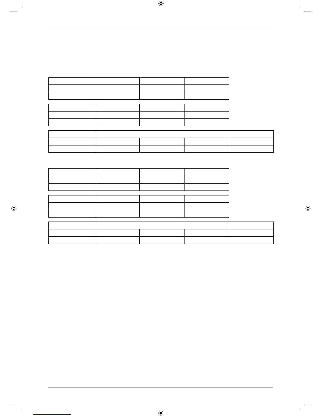
5) Additional Charge
The refrigerant charge has already charged into the outdoor unit. For the piping length of 7.6m, additional
refrigerant charge after vacuuming is not necessary.
When the piping length is more than 7.6m, please use the table below (unit in gram).
Cooling Only
Indoor FFRN25CXV1 FFRN35CXV1 FFRN50CXV1
Outdoor RN25CXV1 RN35CXV1 RN50CXV1
Add. Charge, g/m 11 9 10
Indoor FCRN50EXV1 FCRN60EXV1 FCRN71EXV1
Outdoor RN50CXV1 RN60CXV1 RR71CXV1
Add. Charge, g/m 22 10 24
Indoor FCRN100EXV1 FCRN125EXV1
Outdoor RR90/100DXV1 RR100DXV1 RR100DXY1 RR125DXY1
Add. Charge, g/m 27 24 24 24
Heatpump
Indoor FFQN25CXV1 FFQN35CXV1 FFQN50CXV1
Outdoor RYN25CXV1 RYN35CXV1 RYN50CXV1
Add. Charge, g/m 15 18 12
Indoor FCQN50EXV1 FCQN60EXV1 FCQN71EXV1
Outdoor RYN50CXV1 RYN60CXV1 RQ71CXV1
Add. Charge, g/m 16 16 41
Indoor FCQN100EXV1 FCQN125EXV1
Outdoor RQ90/100DXV1 RQ100DXV1 RQ100DXY1 RQ125DXY1
Add. Charge, g/m 42 37 37 39
Example: FCRN60EXV1 & RN60CXV1 with 13m piping length, additional piping length is 5.5m. Thus,
Additional Charge = 5.5m x 10 g/m
= 55g
•
•
DAIKIN_FFRN.indb 15DAIKIN_FFRN.indb 15 12/27/2012 9:28:09 AM12/27/2012 9:28:09 AM
16
Sound Data
Sound Data
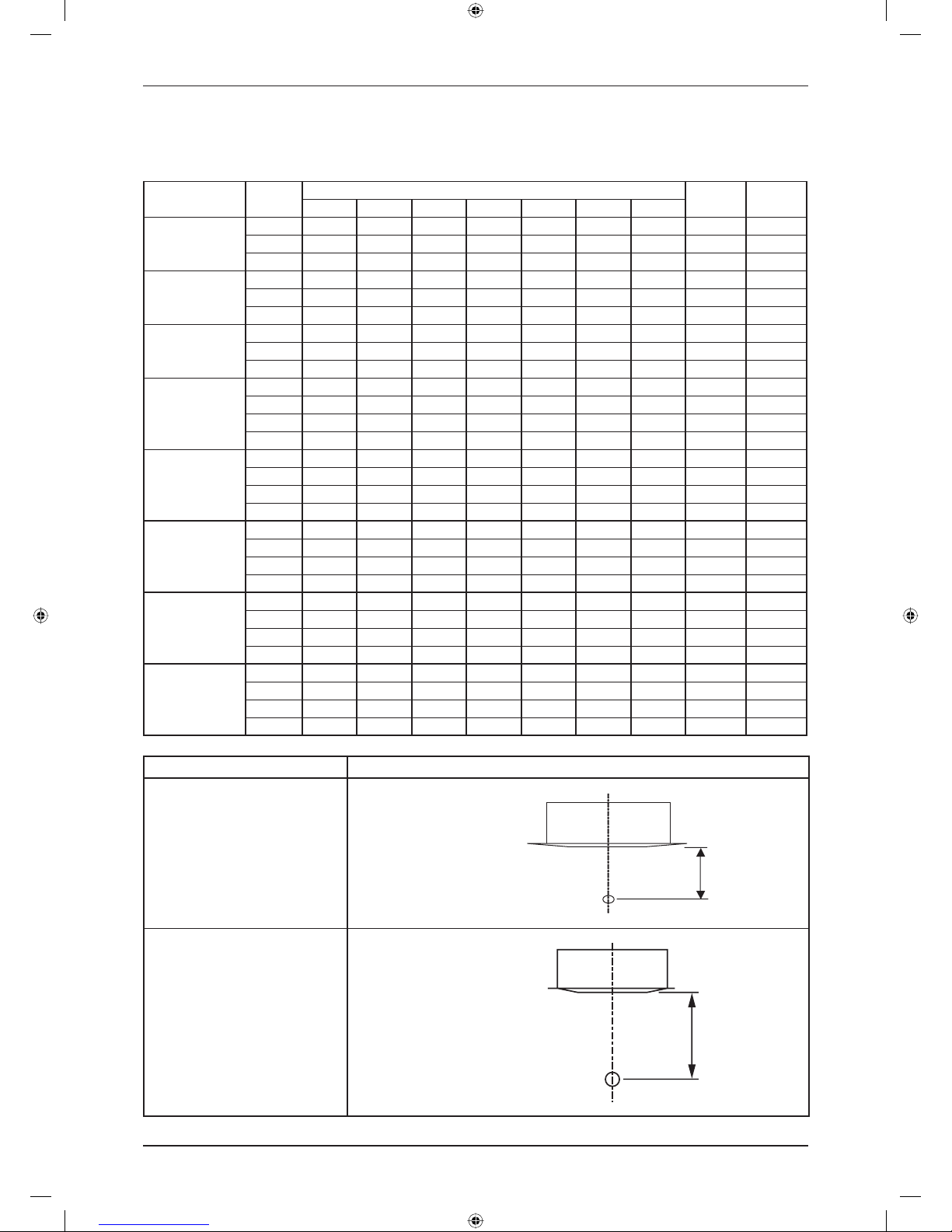
Sound Pressure Level
Model Speed
1/1 Octave Sound Pressure (dB, ref 20μPa)
Overall
(dBA)
Noise
Criteria
125Hz 250Hz 500Hz 1kHz 2kHz 4kHz 8kHz
FF(R)(Q)N25CXV1
High 42 45 40 35 27 20 10 41 35
Med 40 42 37 32 24 15 7 38 32
Low 38 40 34 28 20 10 5 35 29
FF(R)(Q)N35CXV1
High 45 45 40 35 27 20 11 41 35
Med 41 42 37 32 23 15 9 38 32
Low 38 38 33 28 18 9 8 34 28
FF(R)(Q)N50CXV1
High 48 47 43 38 30 24 14 44 38
Med 46 45 40 35 26 19 9 41 35
Low 44 40 36 31 21 12 5 37 31
FC(R)(Q)N50EXV1
High 37 38 35 26 17 8 6 34 30
Med 35 35 34 22 12 6 6 32 29
Low 34 31 31 18 9 6 6 30 25
Quiet 32 28 29 16 7 4 5 28 23
FC(R)(Q)N60EXV1
High 39 40 37 29 22 12 6 37 32
Med 37 37 34 25 17 8 4 34 29
Low 37 37 34 23 15 7 7 33 29
Quiet 36 36 33 22 12 7 8 32 28
FC(R)(Q)N71EXV1
High 46 44 43 36 30 23 12 42 38
Med 39 40 38 30 23 15 7 38 37
Low 38 38 35 26 19 9 5 35 34
Quiet 36 36 33 24 15 6 5 33 30
FC(R)(Q)N100EXV1
High 51 48 47 41 33 31 18 47 43
Med 52 44 44 37 28 24 11 44 39
Low 50 41 40 33 23 15 8 40 35
Quiet 46 36 37 26 15 6 6 36 32
FC(R)(Q)N125EXV1
High 52 50 48 44 35 34 22 49 44
Med 53 45 44 39 29 28 14 45 39
Low 53 43 42 37 27 24 10 43 37
Quiet 51 41 39 32 23 16 6 39 34
Model Measuring Location
FF(R)(Q)N25/35/50CXV1
FC(R)(Q)N50/60/71EXV1
Microphone
1.4m
Standard : JIS C 9612
FC(R)(Q)N100EXV1
FC(R)(Q)N125EXV1
Microphone
1.5m
Standard: JIS B 8616
DAIKIN_FFRN.indb 16DAIKIN_FFRN.indb 16 12/27/2012 9:28:09 AM12/27/2012 9:28:09 AM
17
Sound Data
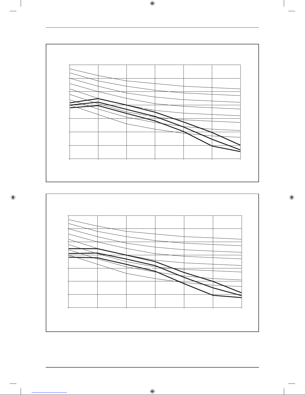
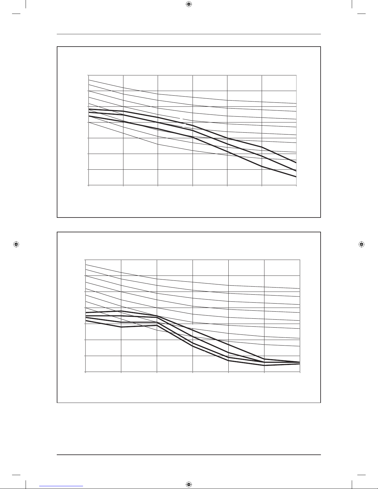
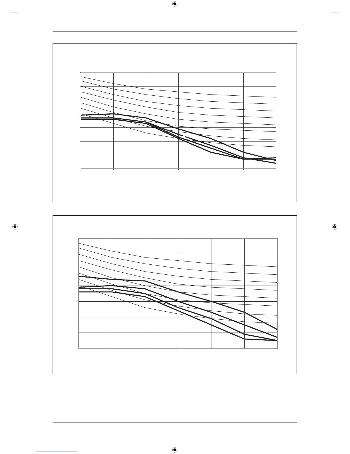
NC Curve
0
10
20
30
40
50
60
70
125 250 500 1000 2000 4000 8000
Octave-band frequency (Hz)
Sound pressure level (dB, ref 20μPa)
NC-20
NC-25
NC-35
NC-40
NC-45
NC-50
NC-55
H
M
L
NC-30
FF(R)(Q)N25CXV1
NC-30
FF(R)(Q)N35CXV1
0
10
20
30
40
50
60
70
125 250 500 1000 2000 4000 8000
Octave-band frequency (Hz)
Sound pressure level (dB, ref 20μPa)
NC-20
NC-30
NC-25
NC-35
NC-40
NC-45
NC-50
NC-55
H
M
L
DAIKIN_FFRN.indb 17DAIKIN_FFRN.indb 17 12/27/2012 9:28:09 AM12/27/2012 9:28:09 AM
18
Sound Data
FF(R)(Q)N50CXV1
0
10
20
30
40
50
60
70
125 250 500 1000 2000 4000 8000
Octave-band frequency (Hz)
Sound pressure level (dB, ref 20μPa)
NC-20
NC-30
NC-25
NC-35
NC-40
NC-45
NC-50
NC-55
L
H
M
FC(R)(Q)N50EXV1
0
10
20
30
40
50
60
70
125 250 500 1000 2000 4000 8000
Octave-band frequency (Hz)
Sound pressure level (dB, ref 20μPa)
NC-20
NC-30
NC-25
NC-35
NC-40
NC-45
NC-50
NC-55
H
M
L
Q
DAIKIN_FFRN.indb 18DAIKIN_FFRN.indb 18 12/27/2012 9:28:09 AM12/27/2012 9:28:09 AM
19
Sound Data
FC(R)(Q)N60EXV1
0
10
20
30
40
50
60
70
125 250 500 1000 2000 4000 8000
Octave-band frequency (Hz)
Sound pressure level (dB, ref 20μPa)
NC-20
NC-30
NC-25
NC-35
NC-40
NC-45
NC-50
NC-55
M
L
Q
H
FC(R)(Q)N71EXV1
0
10
20
30
40
50
60
70
125 250 500 1000 2000 4000 8000
Octave-band frequency (Hz)
Sound pressure level (dB, ref 20μPa)
NC-20
NC-30
NC-25
NC-35
NC-40
NC-45
NC-50
NC-55
M
H
L
Q
DAIKIN_FFRN.indb 19DAIKIN_FFRN.indb 19 12/27/2012 9:28:09 AM12/27/2012 9:28:09 AM
 Loading...