

Daikin RN60CXV1, RN50CXV1, RN60CGXV1, FCRN71EXV1, RR71CXV1 Installation Manual
...
INSTALLATION
MANUAL
MODELS
FCRN50EXV1 RN50C(G)XV1
FCRN60EXV1 RN60C(G)XV1
FCRN71EXV1 RR71C(G)XV1
FCRN100EXV1 RR90D(G)XV1
FCRN125EXV1 RR90D(G)XY1
RR100D(G)XV1
FCQN50EXV1 RR100D(G)XY1
FCQN60EXV1 RR125D(G)XY1
FCQN71EXV1
FCQN100EXV1 RYN50C(G)XV1
FCQN125EXV1 RYN60C(G)XV1
RQ71C(G)XV1
RQ90D(G)XV1
RQ90D(G)XY1
RQ100D(G)XV1
RQ100D(G)XY1
RQ125D(G)XY1
CEILING CASSETTE
R410A SPLIT TYPE AIR CONDITIONER
(E Series)
IM-5CKE-0912(0)DAIKIN
Part No.: R08019038169
English
Français
Deutsch
Italiano
Español
Русский
Türkçe
Installation Manual
R410A Split Type Air Conditioner
Manuel D’installation
Climatiseurs Split System R410A
Installationshandbuch
Doppelfunktions-Klimagerät and R410A
Manuale Di Installazione
Condizionatore Split A R410A
Manual De Instalación
Equipo de air Acondicionado de tipo
Dividido de R410A
Руководство по установке
R410A разделить Кондиционер
воздуха типа
Kurulum kılavuzu
R410A Split Tipi Klima
CVR 5CKE-0912(0)DAIKIN-EN.indd 1CVR 5CKE-0912(0)DAIKIN-EN.indd 1 9/27/12 12:12:39 PM9/27/12 12:12:39 PM
1-1
English
N
L
KL
QN
M
A
D
O
BP
RS
C
HG
E
IJ
F
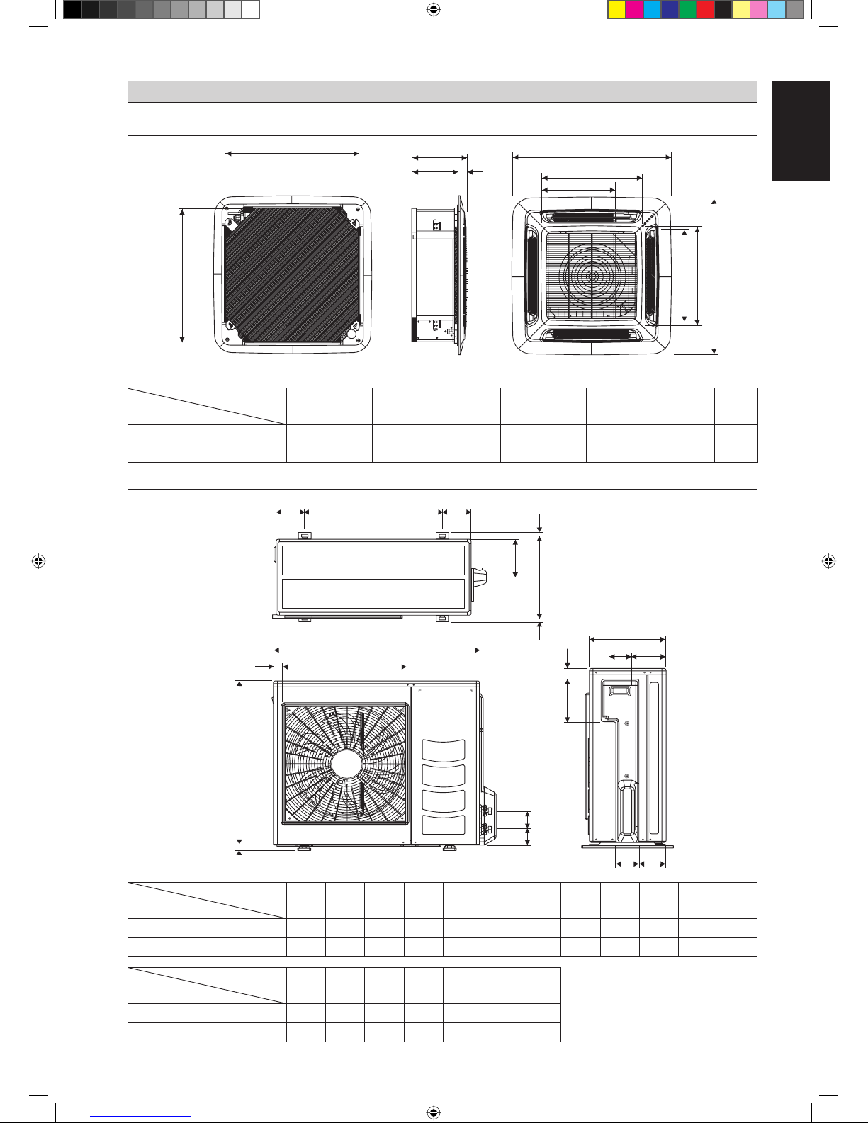
All dimensions are in mm
A
B
C
D
E
F
H
K
J
I
G
Outdoor Unit (RN/RR/RYN/RQ)
All dimensions are in mm
OUTLINE AND DIMENSIONS
Dimension
Model
ABCDE FGHI JKL
50C 855 628 328 520 179 46 93 149 101 113 603 126
60/71C 855 730 328 520 179 46 93 149 101 113 603 126
Dimension
Model
MNOPQR S
50C 164 15 34 23 362 73 75
60/71C 164 15 34 23 362 73 75
Dimension
Model
ABCDE FGHI JK
50/60/71E 820 820 340 300 40 990 990 627 627 607 430
100/125E 820 820 375 335 40 990 990 627 627 607 430
Indoor Unit (FCRN/FCQN)
Original Instruction
1 IM-5CKE-0912(0)DAIKIN-EN.indd 11 IM-5CKE-0912(0)DAIKIN-EN.indd 1 9/28/12 2:04:14 PM9/28/12 2:04:14 PM
1-2
MADE IN MALAYSIA
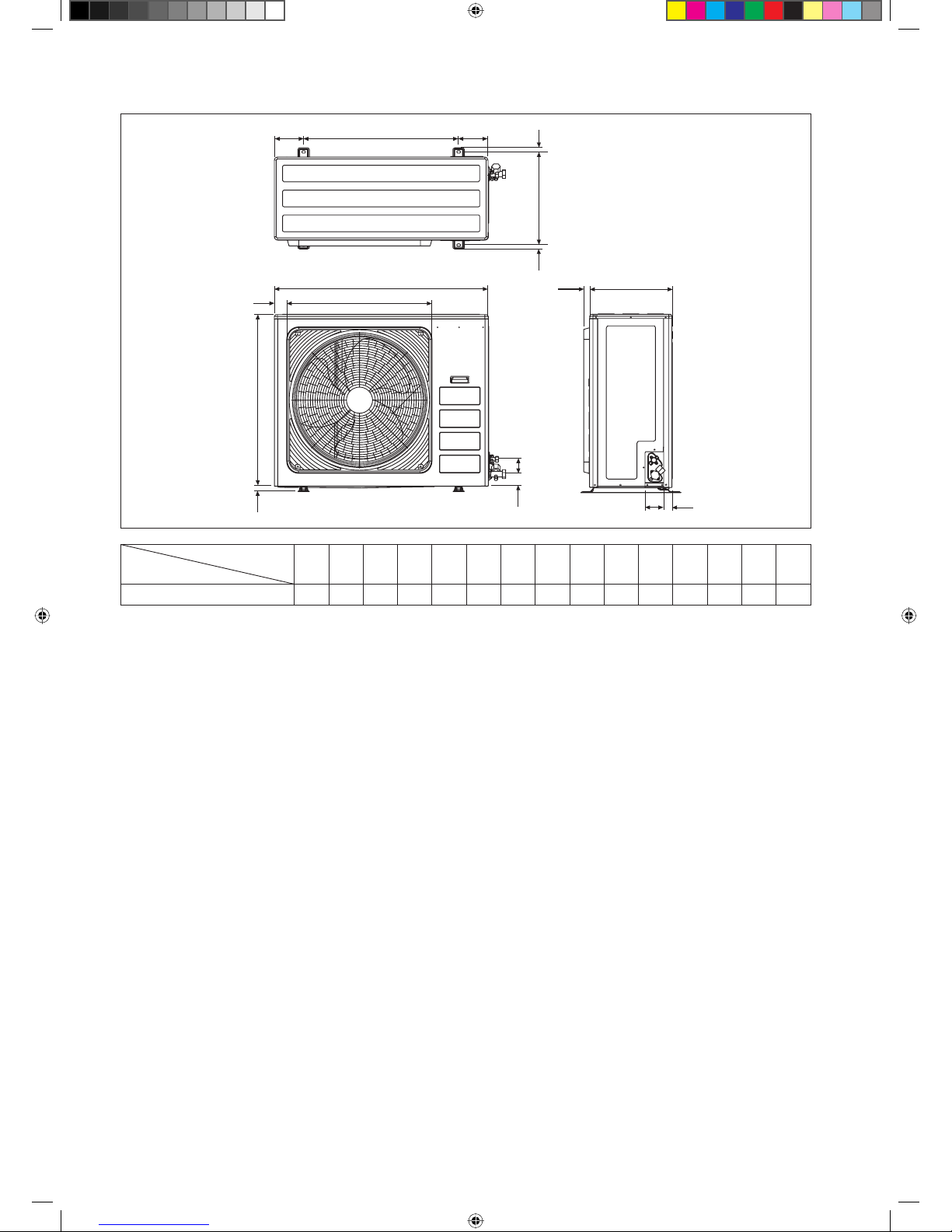
Outdoor Unit (RR/RQ)
All dimensions are in mm
IJJ
D
M
B
G
O
Dimension
Model
ABCDE FGHI JKLMNO
90/100/125D 1030 826 400 410 57 72 90 40 746 142 60 26 448 22 28
NN
K
A
L
EF
H
C
1 IM-5CKE-0912(0)DAIKIN-EN.indd 21 IM-5CKE-0912(0)DAIKIN-EN.indd 2 9/28/12 2:04:14 PM9/28/12 2:04:14 PM
1-3
English
INSTALLATION MANUAL
This manual provides the procedures of installation to ensure a safe and good standard of operation for the air conditioner unit.
Special adjustment may be necessary to suit local requirements.
Before using your air conditioner, please read this instruction manual carefully and keep it for future reference.
This appliance is intended to be used by expert or trained users in shops, in light industry and on farms, or for commercial use
by lay persons.
This appliance is not intended for use by persons, including children, with reduced physical, sensory or mental capabilities, or
lack of experience and knowledge, unless they have been given supervision or instruction concerning use of the appliance by a
person responsible for their safety.
Children should be supervised to ensure that they do not play with the appliance.
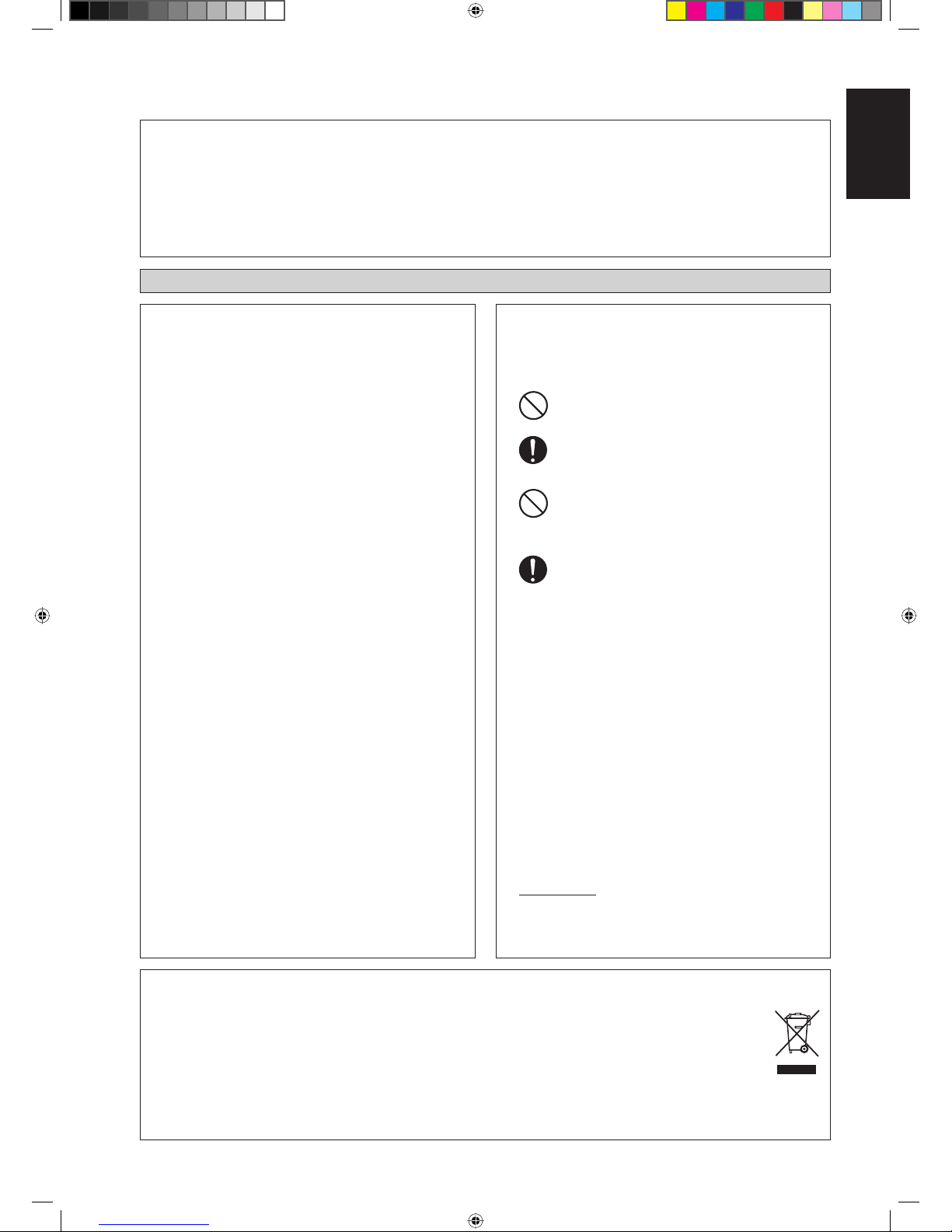
SAFETY PRECAUTIONS
! WARNING ! CAUTION
Installation and maintenance should be performed by
qualified persons who are familiar with local code and
regulation, and experienced with this type of appliance.
All field wiring must be installed in accordance with the
national wiring regulation.
Ensure that the rated voltage of the unit corresponds to
that of the name plate before commencing wiring work
according to the wiring diagram.
The unit must be GROUNDED to prevent possible hazard
due to insulation failure.
All electrical wiring must not touch the refrigerant piping,
or any moving parts of the fan motors.
Confirm that the unit has been switched OFF before
installing or servicing the unit.
Disconnect from the main power supply before servicing
the air conditioner unit.
DO NOT pull out the power cord when the power is ON.
This may cause serious electrical shocks which may result
in fire hazards.
Keep the indoor and outdoor units, power cable and
transmission wiring, at least 1m from TVs and radios, to
prevent distorted pictures and static. {Depending on the
type and source of the electrical waves, static may be heard
even when more than 1m away}.
•
•
•
•
•
•
•
•
•
Please take note of the following important points when
installing.
Do not install the unit where leakage of flammable gas
may occur.
If gas leaks and accumulates around the unit, it may
cause fire ignition.
Ensure that the drainage piping is connected properly.
If the drainage piping is not connected properly, it may
cause water leakage which will dampen the furniture.
Do not overcharge the unit.
This unit is factory pre-charged.
Overcharge will cause over-current or damage to
the compressor.
Ensure that the unit’s panel is closed after service or
installation.
Unsecured panels will cause the unit to operate
noisily.
Sharp edges and coil surfaces are potential locations
which may cause injury hazards. Avoid from being in
contact with these places.
Before turning off the power supply, set the remote
controller’s ON/OFF switch to the “OFF” position to
prevent the nuisance tripping of the unit. If this is not done,
the unit’s fans will start turning automatically when power
resumes, posing a hazard to service personnel or the user.
Do not install the units at or near doorway.
Do not operate any heating apparatus too close to the air
conditioner unit or use in room where mineral oil, oil vapour
or oil steam exist, this may cause plastic part to melt or
deform as a result of excessive heat or chemical reaction.
When the unit is used in kitchen, keep flour away from
going into suction of the unit.
This unit is not suitable for factory used where cutting oil
mist or iron powder exist or voltage fluctuates greatly.
Do not install the units at area like hot spring or oil refinery
plant where sulphide gas exists.
Ensure the color of wires of the outdoor unit and the terminal
markings are same to the indoors respectively.
IMPORTANT : DO NOT INSTALL OR USE THE AIR
CONDITIONER UNIT IN A LAUNDRY ROOM.
Don’t use joined and twisted wires for incoming power supply.
The equipment is not intended for use in a potentially
explosive atmosphere.
•
•
•
•
•
•
•
•
•
•
•
•
•
•
•
NOTICE
Disposal requirements
Your air conditioning product is marked with this symbol. This means that electrical and electronic products shall not
be mixed with unsorted household waste.
Do not try to dismantle the system yourself: the dismantling of the air conditioning system, treatment of the refrigerant, of
oil and of other parts must be done by a qualified installer in accordance with relevant local and national legislation.
Air conditioners must be treated at a specialized treatment facility for re-use, recycling and recovery. By ensuring this
product is disposed of correctly, you will help to prevent potential negative consequences for the environment and
human health. Please contact the installer or local authority for more information.
Batteries must be removed from the remote controller and disposed of separately in accordance with relevant local
and national legislation.
1 IM-5CKE-0912(0)DAIKIN-EN.indd 31 IM-5CKE-0912(0)DAIKIN-EN.indd 3 9/28/12 2:04:14 PM9/28/12 2:04:14 PM
1-4
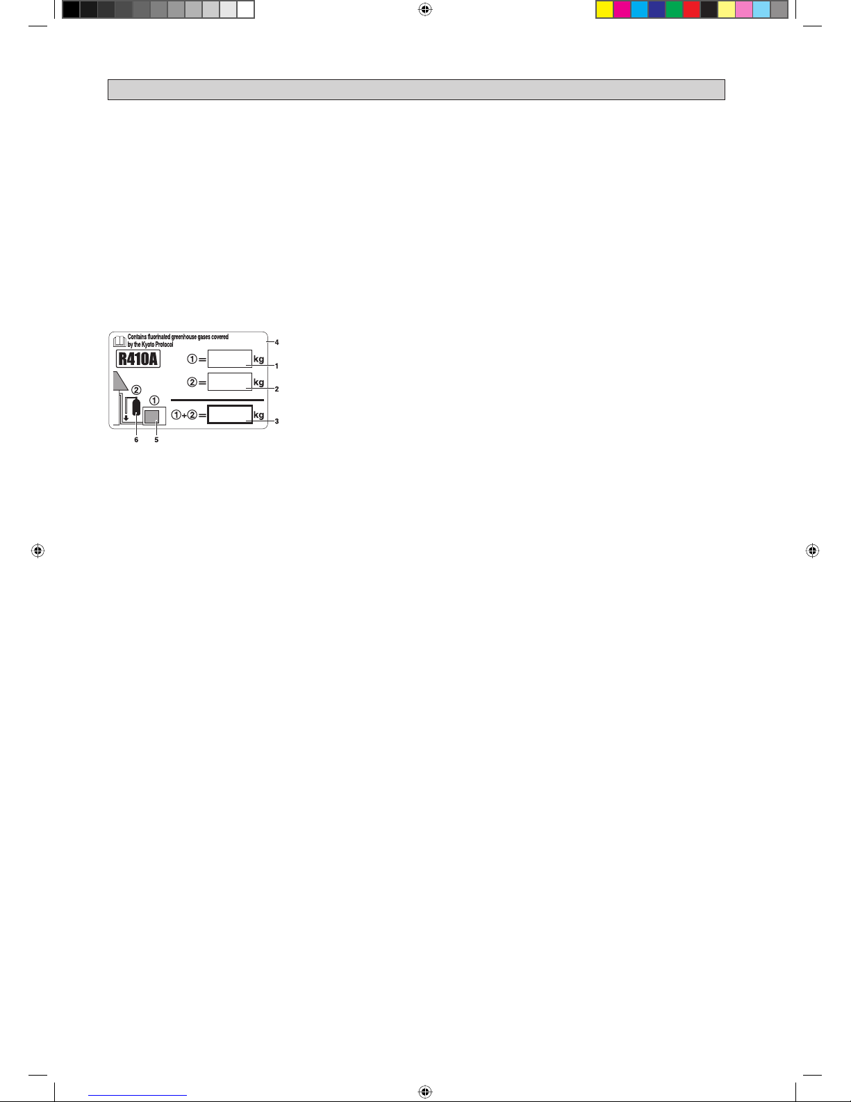
IMPORTANT
Important information regarding the refrigerant used
This product contains fluorinated greenhouse gases covered by the Kyoto Protocol.
Do not vent gases into the atmosphere.
Refrigerant type: R410A
GWP
(1)
value: 1975
(1)
GWP = global warming potential
Please fill in with indelible ink,
1 the factory refrigerant charge of the product,
2 the additional refrigerant amount charged in the field and
1 + 2 the total refrigerant charge
on the refrigerant charge label supplied with the product.
The filled out label must be adhered in the proximity of the product charging port (e.g. onto the inside of the service cover).
1 factory refrigerant charge of the product:
see unit name plate
(2)
2 additional refrigerant amount charged in the field
3 total refrigerant charge
4 contains fluorinated greenhouse gases covered by the Kyoto Protocol
5 outdoor unit
6 refrigerant cylinder and manifold for charging
(2)
In case of multiple indoor systems, only 1 label must be adhered*, mentioning the total factory refrigerant charge of all
indoor units connected in the refrigerant system.
Periodical inspections for refrigerant leaks may be required depending on European or local legislation. Please contact your
local dealer for more information.
* on the outdoor unit
■
■
■
1 IM-5CKE-0912(0)DAIKIN-EN.indd 41 IM-5CKE-0912(0)DAIKIN-EN.indd 4 9/28/12 2:04:15 PM9/28/12 2:04:15 PM
1-5
English
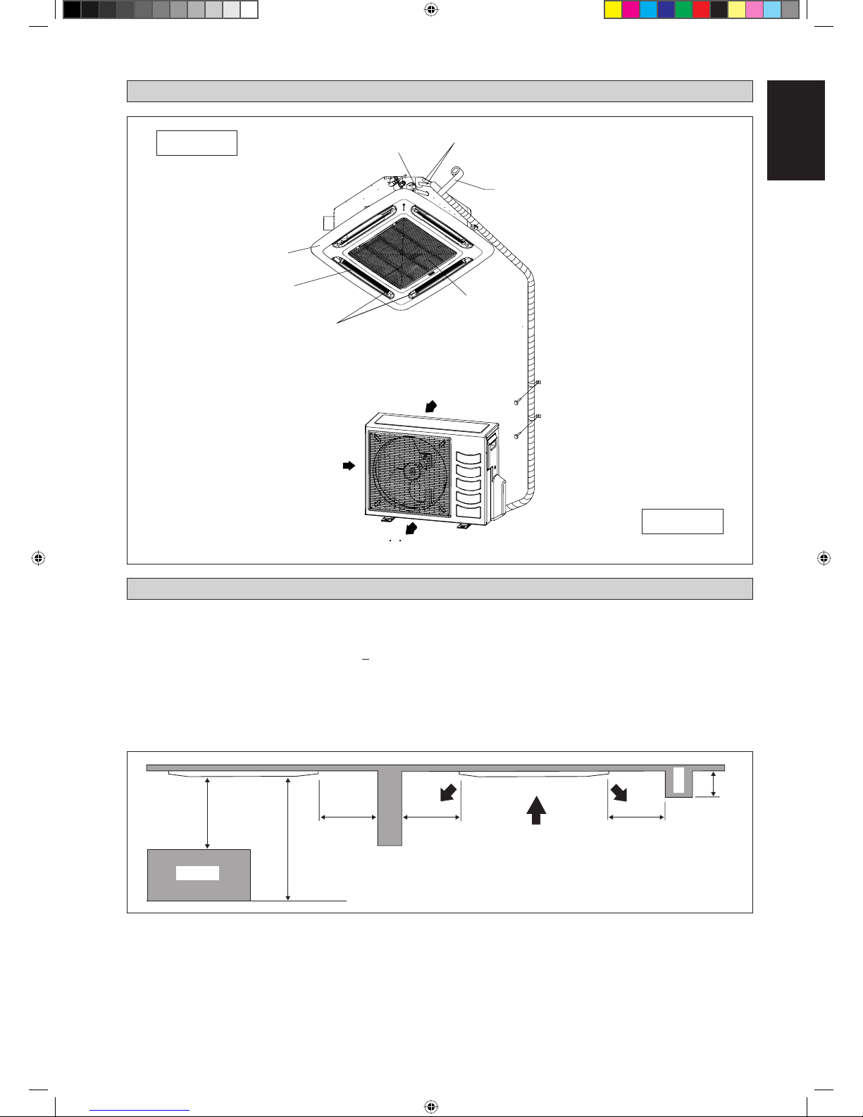
INSTALLATION DIAGRAM
INSTALLATION OF THE INDOOR UNIT
Preliminary Site Survey
Be sure to read this manual before installing the air-conditioner indoor unit.
Voltage supply fl uctuation must not exceed +10% of rated voltage. Electricity supply lines must be independent of
welding transformers which can cause high supply fl uctuation.
Ensure that the location is convenient for wiring, piping and drainage.
Do not exert pressure on the resin parts when opening the unit or when moving it after opening.
Do not move the unit from packaging while moving, until it reaches the installation site. Use safe material or protection
plates when unpacking it or lifting it to avoid damage or scratches to the unit.
•
•
•
•
Drain Piping
Front Panel
Air Filter
(behind the grille)
Air Intake Grille
Air Discharge
Air Discharge Louver
Air Intake
Air Intake
Thermal Insulation
Wrap the insulated pipe with the
fi nishing tape from bottom to top
Indoor Unit
Outdoor Unit
0.5m or more 0.5m or more 0.5m or more
0.3m or less
3m or more
1m or more
Floor
Obstacle
Beam
1 IM-5CKE-0912(0)DAIKIN-EN.indd 51 IM-5CKE-0912(0)DAIKIN-EN.indd 5 9/28/12 2:04:15 PM9/28/12 2:04:15 PM
1-6
Ensure a location where:
Drainage can be done easily.
Convenient for wiring and piping.
Which have enough space for installation and service work.
Where no risk of flammable gas leakage.
When free from any obstacles in path of cool air discharge and warm air return and must allow spreading of air
throughout the room (near the center of the room).
Must be provided clearance for indoor unit from the wall and obstacles as shown in figure below.
The installation place must be strong enough to support a load 4 times the indoor unit weight to avoid amplifying
noise and vibration.
The installation place (hanging ceiling surface) must be assuring levelness and the height in the ceiling is 350mm or
more.
The indoor unit must be away from heat and steam sources (avoid installing it near an entrance).
•
a)
b)
c)
d)
e)
f)
g)
h)
i)
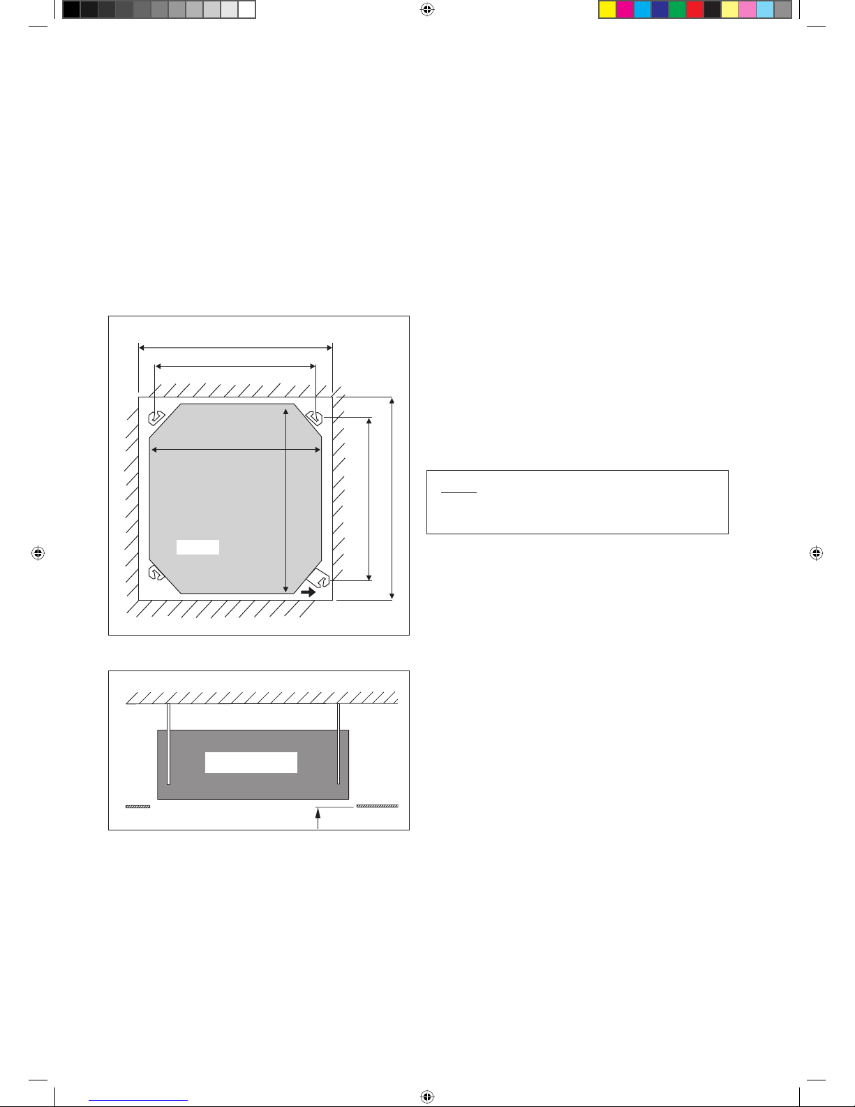
Unit Installation
Measure and mark the position for the hanging rod.
Drill the hole for the angle nut on the ceiling and fix the
hanging rod.
The installation template is extended according to
temperature and humidity. Check on dimensions in use.
The dimensions of the installation template are the same
as those of the ceiling opening dimensions.
Before ceiling laminating work is completed, be sure to
fit the installation template to the indoor unit.
•
•
•
•
NOTE
Be sure to discuss the ceiling drilling work with the
installers concerned.
Unit Hanging
Hold the unit and hang it on the hanging rod with the nut
and washer.
Adjust the unit height to 30mm between the indoor unit
bottom surface and the ceiling surface.
Confirm with a level gauge that the unit is installed
horizontally and tighten the nut and bolt to prevent unit
falling and vibration.
Open the ceiling board along the outer edge of the paper
installation template.
•
•
•
•
Unit size 820mm
Piping Direction
Ceiling Opening Size = 890mm
Ceiling Opening Size = 890mm
Hanging Rod Size = 790mm
Unit size 820mm
Unit
Indoor Unit
30 mm
Ceiling
Board
Hanging Rod Size = 621mm
1 IM-5CKE-0912(0)DAIKIN-EN.indd 61 IM-5CKE-0912(0)DAIKIN-EN.indd 6 9/28/12 4:27:24 PM9/28/12 4:27:24 PM
1-7
English
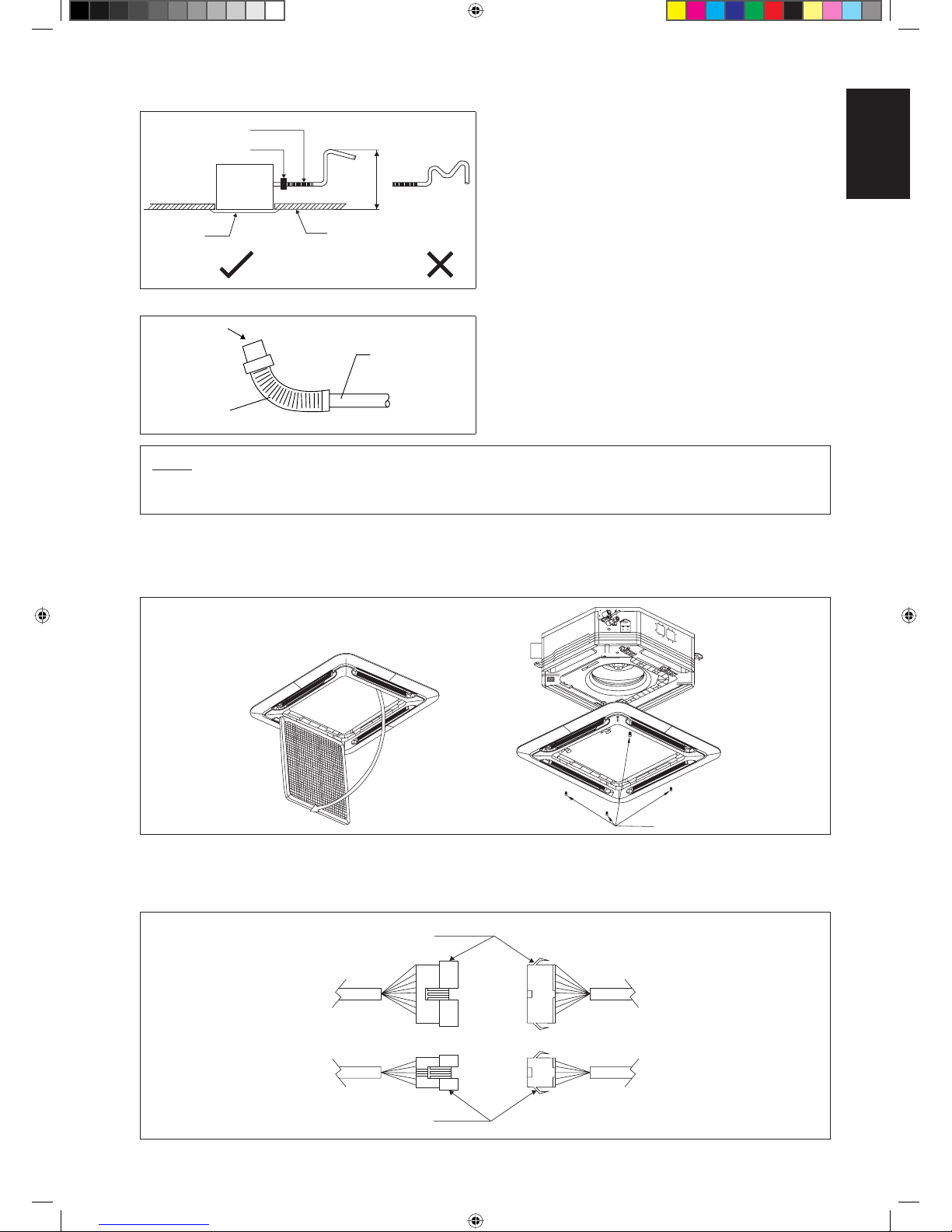
Drain Piping Work
Avoid installing the drain pipe in upward gradient after
the drain connection.
Ensure the height of drain pipe from ceiling is 700mm or
less if it is necessary to increase the height of drain pipe
to prevent water leak.
Avoid installing the drain pipe in up and down slope to
prevent reversed water flow.
During the drain pipe connection, be careful not to exert
extra force on the drain connector at indoor unit.
The outside diameter of the drain connection at the
flexible drain hose is 20mm.
Be sure to execute heat insulation (polyethylene foam
with thickness more than 8mm) on the drain piping to
avoid the condensed water dripping inside the room.
Connect the main drain pipe to the flexible drain hose.
Feed water from flexible drain hose to check the piping
for leakage.
When the test is completed, connect the flexible drain
hose to the drain connector on the indoor unit.
•
•
•
•
•
•
•
•
•
Drain Test
NOTE
This Indoor Unit uses a drain pump for condensed water drainage. Install the unit horizontally to prevent water leakage
or condensation around the air outlet.
Panel Installation
The front panel can only be fitted in one direction, follow the piping direction. (Follow piping arrow sticker on front
panel)
Be sure to remove the installation template before installing the front panel.
•
•
Open the air intake grille by pulling back the catchers and removing it together with filter from panel.
Install the front frame panel onto the indoor unit by 4 screws and tighten it completely to prevent cool air leakage.
Connect the LED wire and air swing wire to the indoor unit.
The air swing connector must put inside the control box after connected.
•
•
•
•
Main Drain Pipe
Feed Water
Flexible Drain Hose
Open
Screw
From Unit
Control Box
From Front
Panel
LED Wire
Air Swing Wire
Pipe Clamp
Ceiling
700.0mm or less
Panel
Flexible Hose
Indoor
Unit
1 IM-5CKE-0912(0)DAIKIN-EN.indd 71 IM-5CKE-0912(0)DAIKIN-EN.indd 7 9/28/12 2:04:16 PM9/28/12 2:04:16 PM
 Loading...