

Daikin FAQ100BUV1B, RR71B7V3B, FAQ100B7V3B, FAQ71B7V3B, RR71B7W1B Technical Data Manual
...Page 1
FAQ-BU
Wall Mounted Unit
technical data
Split
Sky Air
air conditioning systems
Page 2
Split - Sky Air
EEDE05-1/3 • 05/2005
Prepared in Belgium by Goekint Graphics
B - 8400 Ostend Belgium
Specifications are subject to change without prior notice.
ISO14001 assures an effective environmental
management system in order to help protect
human health and the environment from the potential
impact of our activities, products and services and to
assist in maintaining and improving the quality of
the environment
Daikin Europe N.V. is approved by LRQA for its Quality
Management System in accordance with the ISO9001
standard. ISO9001 pertains to quality assurance regarding
design, development, manufacturing as well as to services
related to the product.
Daikin units comply with the European
regulations that guarantee the safety of
the product.
Daikin Europe N.V. participates in the Eurovent Certification
Programme for Air Conditioners (AC), Liquid Chilling Packages
(LCP) and Fan Coil Units (FC); the certified data of certified
models are listed in the Eurovent Directory.
www.daikineurope.com
Zandvoordestraat 300
Page 3
TABLE OF CONTENTS
FAQ-BU
1 Features ................................................................................. 2
2 Specifications
....................................................................... 3
Nominal capacity, capacity steps and nominal input
Technical specifications
3 Dimensional drawings ..................................................... 6
4 Piping diagrams
.................................................................. 7
5 Wiring diagrams
................................................................. 8
6 Sound level
.......................................................................... 10
Sound level data
Sound pressure spectrum
7
Air flow patterns
................................................................. 11
8 Accessories
.......................................................................... 15
Standard accessories
Optional accessories
9 Control systems .................................................................. 16
10 Safety device settings
...................................................... 17
11 Installation
............................................................................ 17
For capacity tables, please refer to part II: outdoor units
•
Wall Mounted, Inverter Controlled Unit • R-410A • FAQ71-100BUV1B
1
• Split - Sky Air • Indoor Units
Page 4
1
Features
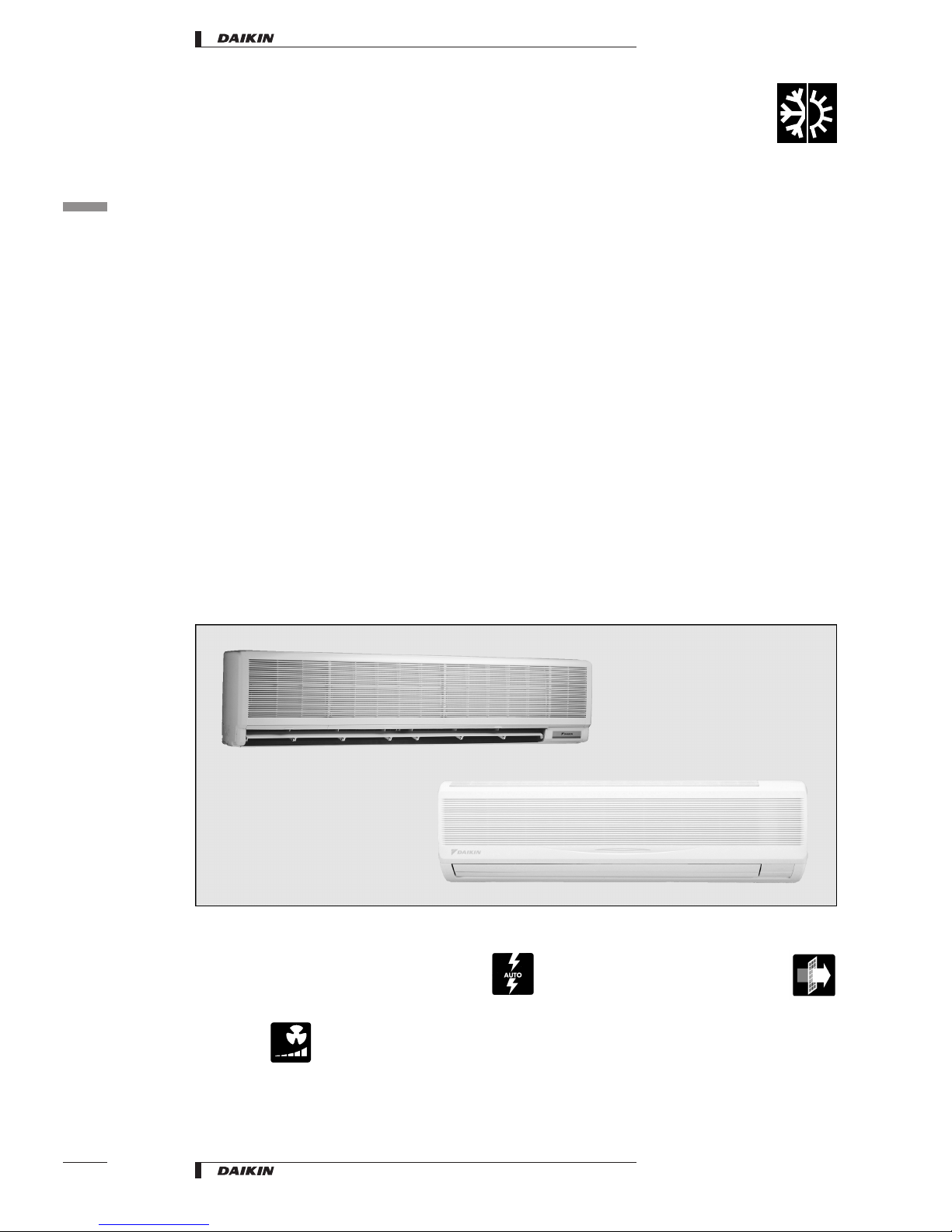
+ Ideal for shops, restaurants or offices requiring maximum floor
space for furniture and fittings
+ The 71 class has a modern casing: it is very compact (290mm
height - 1050mm width) and very lightweight (only 13 kg).
+ Fits neatly on a wall
+ Automatic air flow director ensures uniform air flow and
temperature distribution
+ The flap of the unit is closed when not operating.
+ The front panel of the new casing is easy removable and
washable.
+ Extremely quiet in operation both indoors and outdoors
+ For equal distribution in larger rooms, up to 3 indoor units can
be connected to 1 outdoor. They are operated from 1 remote
control
+ These indoor units can also be connected to the Sky Air super
inverter RZQ-B.
+ Daikin remote controls give you easy control at your fingertips.
+ The wired remote control provides you with a schedule timer,
enabling to program the air conditioning daily or weekly.
+ The optional remote ON/OFF enables you to start/stop the air
conditioning from a mobile phone via a telephone remote
control (field supply).
+ The optional forced OFF enables you to switch off the unit
automatically. E.g. when a window is opened, the unit switches
off.
+ The ’home leave’ operation button prevents large temperature
differences by continuously operating at a minimum (heating
mode) or maximum (cooling mode) preset level while you’re
out or sleeping. It also allows the indoor temperature to return
quickly to your favourite comfort level.
2130 8qx
6 )(6
Optional Optional
Heat pump
2 steps
Optional
Twin / Triple
•
Wall Mounted, Inverter Controlled Unit • R-410A • FAQ71-100BUV1B
1
1
2
• Split - Sky Air • Indoor Units
Page 5
2
Specifications
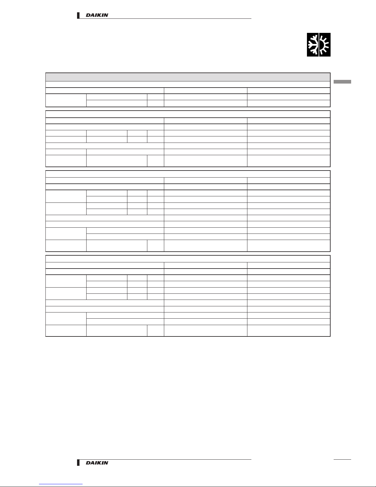
NOMINAL CAPACITY and NOMINAL INPUT
For indoor units only:
INDOOR UNITS FAQ71BUV1B FAQ100BUV1B
NOMINAL INPUT Cooling kW 0.068 0.101
Heating kW 0.068 0.101
For combination indoor + outdoor units (air cooled):
INDOOR UNITS FAQ71B7V3B FAQ100B7V3B
OUTDOOR UNITS RR71B7V3B/RR71B7W1B RR100B7V3B/RR100B7W1B
NOMINAL CAPACITY (3) Cooling (1) nominal kW 7.10 10.00
NOMINAL INPUT Cooling nominal kW 2.65/2.53 3.56/3.52
EER 2.68/2.81 2.81/2.84
ENERGY LABEL Cooling D/C C/C
ANNUAL ENERGY
CONSUMPTION
Cooling kWh 1,325 1,780
For combination indoor + outdoor units (air cooled):
INDOOR UNITS FAQ71B7V3B FAQ100B7V3B
OUTDOOR UNITS RQ71B7V3B/RQ71B7W1B RQ100B7V3B/RQ100B7W1B
NOMINAL CAPACITY (3) Cooling (1) nominal kW 7.10 10.10
Heating (2) nominal kW 8.00 11.20
NOMINAL INPUT Cooling nominal kW 2.65/2.53 3.56/3.52
Heating nominal kW 2.58/2.49 3.96/3.82
EER 2.68/2.81 2.81/2.84
COP 3.10/3.21 2.83/2.93
ENERGY LABEL Cooling D/C C/C
Heating D/C D/D
ANNUAL ENERGY
CONSUMPTION
Cooling kWh 1,325 1,780
For combination indoor + outdoor units (air cooled):
INDOOR UNITS FAQ71BUV1B FAQ100BUV1B
OUTDOOR UNITS RZQ71B8V3B RZQ100B8V3B/B7W1B
NOMINAL CAPACITY (3) Cooling (1) nominal kW 7.10 10.00
Heating (2) nominal kW 8.00 11.20
NOMINAL INPUT Cooling nominal kW 2.36 2.78
Heating nominal kW 2.42 3.39
EER 3.01 3.6
COP 3.31 3.30
ENERGY LABEL Cooling B A
Heating C C
ANNUAL ENERGY
CONSUMPTION
Cooling kWh 1,180 1,390
•
Wall Mounted, Inverter Controlled Unit • R-410A • FAQ71-100BUV1B
1
2
3
• Split - Sky Air • Indoor Units
Page 6
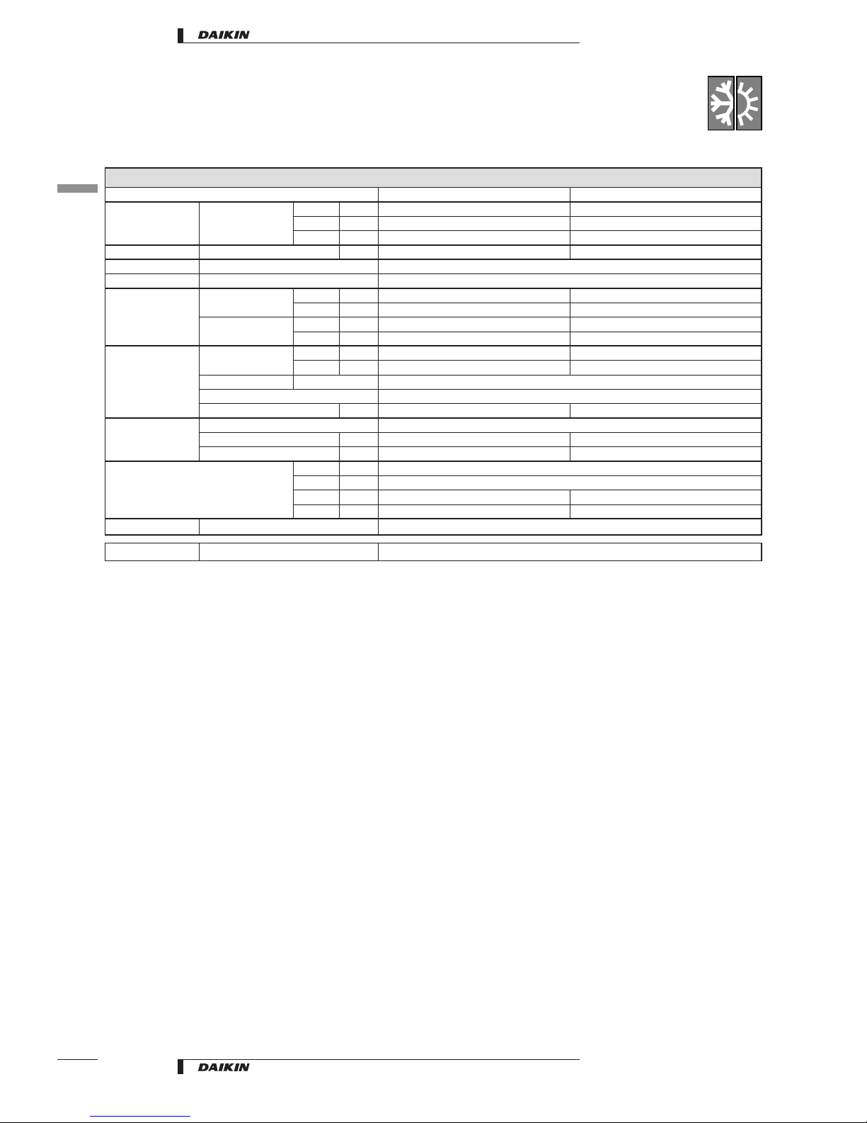
TECHNICAL SPECIFICATIONS
INDOOR UNITS FAQ71BUV1B FAQ100BUV1B
DIMENSIONS Unit H mm 290 360
W mm 1,050 1,570
D mm 230 200
WEIGHT Unit kg 13 26
MATERIAL Unit Resin
COLOUR Unit White
SOUND LEVEL
Sound pressure (cooling/heating) (4)
high dB(A) 43/43 45/45
low dB(A) 37/37 41/41
Sound power (cooling/heating) (5)
high dB(A) 59/59 61/61
low dB(A) 53/53 57/57
FAN Air flow rate high m
3
/min 19/19 23/23
low m
3
/min 15/15 19/19
Speed steps 2 steps
Type Cross flow fan
Qty x motor output W 1 x 43 1 x 49
HEAT EXCHANGER Type Cross fin coil (Multi louver fins and Hi-XA tubes)
Rows x stages x fin pitch mm 2 x 16 x 1.4 2 x 12 x 1.4
Face area m
2
0.289 0.332
PIPING CONNECTIONS liquid mm φ9.5 (flare)
gas mm φ15.9 (flare)
drain I.D. mm φ13 (VP13) φ20 (VP20)
drain O.D. mm φ18 (VP13) φ26 (VP20)
INSULATION MATERIAL Heat insulation Foamed polystyrene/foamed polyethylene
For outdoor units
Pair / Twin / Triple application See chapter RR-B / RQ-B / RZQ-B
•
Wall Mounted, Inverter Controlled Unit • R-410A • FAQ71-100BUV1B
2
Specifications
1
2
4
• Split - Sky Air • Indoor Units
Page 7
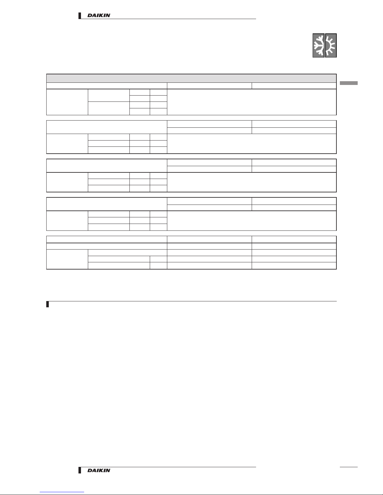
ELECTRICAL SPECIFICATIONS
For indoor units only: FAQ71BUV1B FAQ100BUV1B
CURRENT Nominal running current
cooling
A
See chapter RR-B7, RQ-B7, RZQ-B
heating
A
Max. running current
cooling
A
heating
A
For combination indoor + outdoor units (air cooled): FAQ71B7V3B FAQ100B7V3B
RR71B7V3B/RR71B7W1B RR100B7V3B/RR100B7W1B
CURRENT Nominal running current
cooling
A
See chapter RR-B7Maximum running current
cooling
A
Starting current
cooling
A
For combination indoor + outdoor units (air cooled): FAQ71BUV1B FAQ100BUV1B
RQ71B7V3B/RQ71B7W1B RQ100B7V3B/RQ100B7W1B
CURRENT Nominal running current
cooling
A
See chapter RQ-B7Maximum running current
cooling
A
Starting current
cooling
A
For combination indoor units + outdoor units: FAQ71BUV1B FAQ100BUV1B
RZQ71B8V3B RZQ100B8V3B/B7W1B
CURRENT Nominal running current
cooling
A
See chapter RZQ-BMaximum running current
cooling
A
Starting current
cooling
A
For indoor units only: FAQ71BUV1B FAQ100BUV1B
POWER SUPPLY V1 V1
NOMINAL DISTRIBUTION
SYSTEM VOLTAGE
Phase 1∼ 1∼
Frequency Hz 50 50
Voltage V 220-240 220-240
4D043953
NOTES
1 Nominal cooling capacities are based on: indoor temperature 27°CDB/19.5°CWB * outdoor temperature 35°CDB * equivalent refrigerant piping
length: 7.5m * level difference: 0m.
2 Nominal heating capacities are based on: indoor temperature: 20°CDB * outdoor temperature: 7°CDB/6°CWB * refrigerant piping length: 7.5m *
level difference 0m.
3 Capacities are net, including a deduction for cooling (an addition for heating) for indoor fan motor heat.
4 The sound pressure level is measured via a microphone at 1m distance from the unit. It is a relative value, depending on the distance and
acoustic environment. For measuring conditions: please refer to item 6 of this chapter.
5 The sound power level is an absolute value indicating the ’’power’’ which a sound source generates.
6 Energy label: scale from A (most efficient) to G (less efficient).
7 Annual energy consumption: based on average use of 500 running hours per year at full load (= nominal conditions).
•
Wall Mounted, Inverter Controlled Unit • R-410A • FAQ71-100BUV1B
2
Specifications
1
2
5
• Split - Sky Air • Indoor Units
Page 8
3
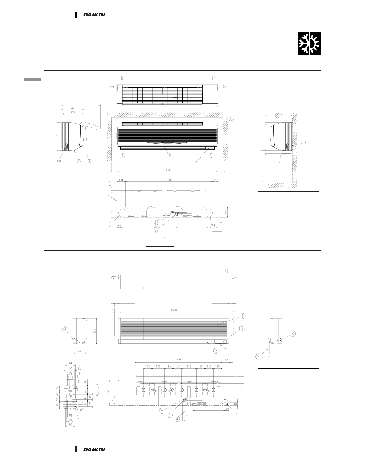
Dimensional drawings
unit (mm)
50 or more
30 or more
(Required space)
J80 hole
approx. 345
approx. 475
FAQ71BUV1B
approx. 400
Mounting location
approx. 390
Piping direction
(Required space)
50 or more
Dimensions for
full open front
panel
Outside line
J80 hole
(piping and wiring
intake)
2500 or more
For installation in high
spaces
(Required space)
120 or less
1 Front panel
2 Front grille
3 Air outlet
4 Gas pipe (J15.9 Flare connection)
5 Liquidpipe(J9.5 Flare connection)
6 Drain hose VP13 (External dia J18)
7 Grounding terminal (M4)
8 Right side piping connection hole
9 Left side drain piping connection hole
3D038540B
Notes:
1 Location of general rated name plate
Right side plate outside surface
2 In case of using infrared remote control,
this position will be a signal receiver.
Refer to the drawing of infrared remote
control in detail.
Name plate
50 or more
Piping direction
Note) 2
Piping direction
(Required space)
unit (mm)
50 or more
250 or more
(Required space)
J80 hole
approx. 450
approx. 600
FAQ100BUV1B
8-5x20 Oval hole (for wood screw)
Mounting location
Detail
j
A
(Mounting hole for installation plate)
approx. 580
Piping direction
(Required space)
50 or more
50 or more
(Required space)
5-6x20 Oval hole (for wood screw)
13-J5 Hole (for wood screw)
2-J12 Hole (for bolt)
(piping and wiring
intake)
Note 2. (service space for air filter)
Direction for air filter draw out
1 Front grille
2 Air filter
3 Discharge outlet
4 Gas piping connection (J15.9 flare)
5 Gas piping connection (J9.5 flare)
6 Drain pipe connection (VP20 O.D. J26)
7 Earth terminal(M4) (inside cover)
8 Slit hole for right side piping connection
9 Slit hole for left side piping connection
3D044897
Notes:
1 Location of general rated name plate
Right side plate outside surface
2 In case of using infrared remote control, this
position will be a signal receiver. Refer to the
drawing of infrared remote control in detail.
Brand name plate
Ceiling surface
•
Wall Mounted, Inverter Controlled Unit • R-410A • FAQ71-100BUV1B
1
3
6
• Split - Sky Air • Indoor Units
Page 9
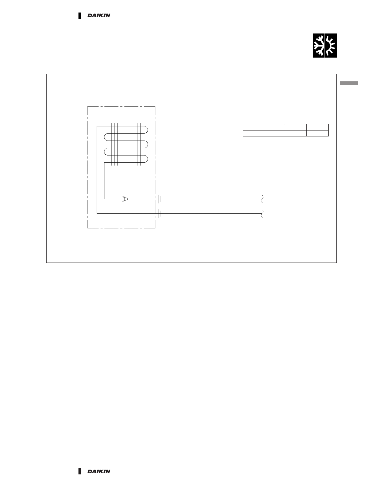
4
Piping diagrams
O Check valve L Flare connection M Screw connection N Flange connection Z Pinched pipe P Spinned pipe
Indoor heat exchanger
Field piping J9.5 C1220T-0
4D037995A
FAQ71-100BUV1B
Field piping J15.9 C1220T-0
Refrigerant pipe connection port diameters
Model A B
FAQ71, 100BUV1B J 9.5 J 15.9
To outdoor unit
Indoor unit
•
Wall Mounted, Inverter Controlled Unit • R-410A • FAQ71-100BUV1B
1
4
7
• Split - Sky Air • Indoor Units
Page 10
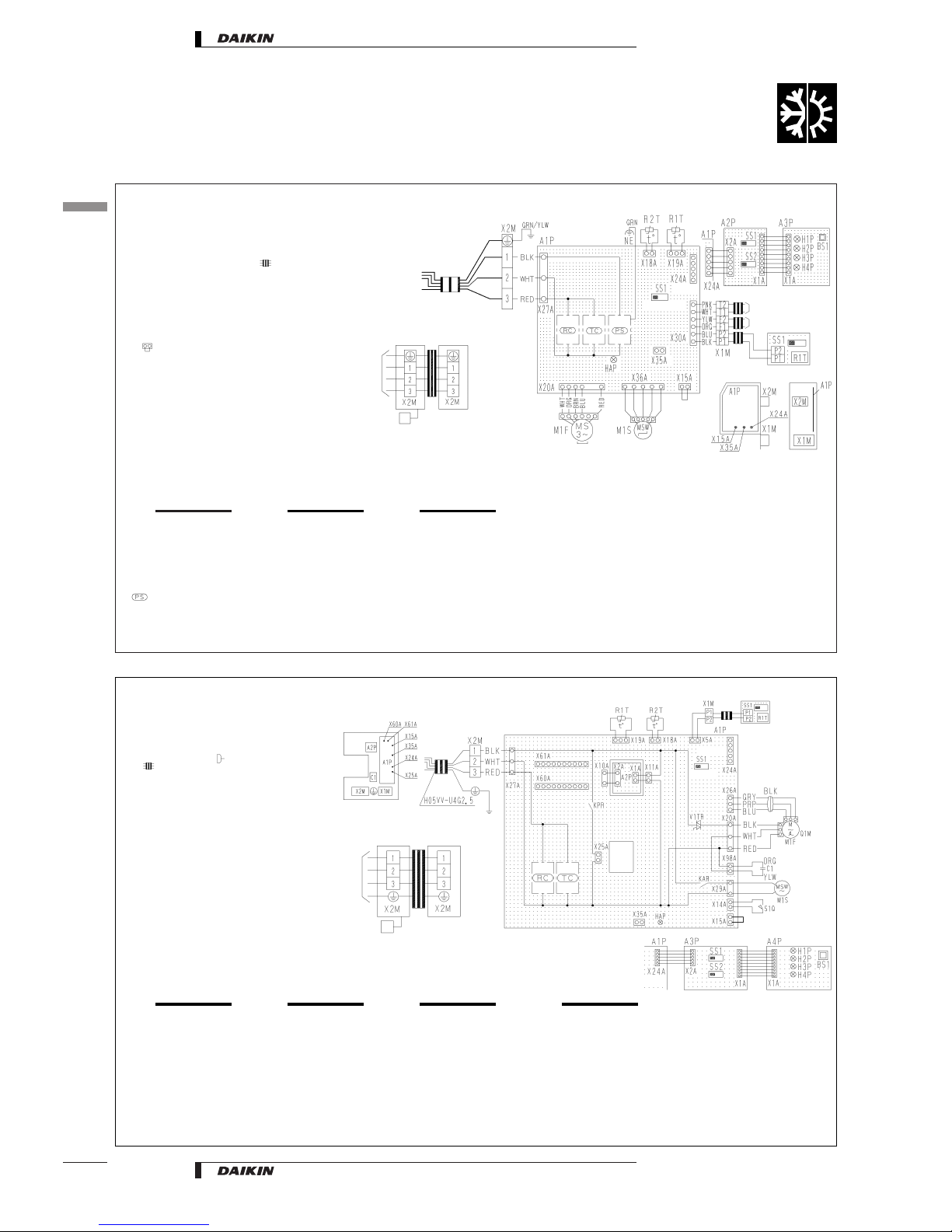
5
Wiring diagrams
3D043881
FAQ71BUV1B
A1P Printed circuit board
HAP Light emitting diode (service monitor green)
M1S Motor (swing flap)
M1F Motor (indoor fan)
R1T Thermistor (air)
R2T Thermistor (coil)
SS1 Selector switch (emergency)
X1M Terminal block
X2M Terminal block
Power supply
? Signal receiver circuit
. Signal transmission circuit
Infrared remote control
Receiver / display unit
A2P Printed circuit board
A3P Printed circuit board
BS1 Push button (on/off)
H1P Light emitting diode (on-red)
H2P Light emitting diode (timer-green)
H3P Light emitting diode (filter sign-red)
H4P Light emitting diode (defrost-orange)
SS1 Selector switch (main/sub)
SS2 Selector switch (wireless address set)
Connector for optional parts
X15A Connector (float switch)
X35A Connector (group control adapter)
Wired remote control
R1T Thermistor (air)
SS1 Selector switch (main/sub)
To outdoor
unit
Note) 4
In case of simultaneous
operation system.
To outdoor unit
Notes
1. D : Terminal, F: Connector,
: Field wiring
2. In case using central remote control, connect it to the
unit in accordance with the attached instruction
manual.
3. Remote control model varies according to the
combination system, confirm technical materials and
catalogs, etc. before connecting.
4. X24A is connected when the infrared remote control
kit is being used.
5.
Shows short circuit connector
6. Symbols show as follows Red:red, Blk:black, Ylw:yellow,
Org:orange, Gry:gray, Prp:purple, Blu:blue
7. Confirm the method of setting the selector switch (SS1,
SS2) by installation manual and engeneering materials,
etc.
Receiver / display unit (attached to infrared remote control)
Note) 4
Indoor unit
(master)
Indoor unit
(slave)
Remote control
Norm. Emerg.
Note) 2
Transmission wiring
connection/central remote
control
Wired remote control
Control box
SIDE
FRONT
ON/OFF input from outside
3D044228
FAQ100BUV1B
A1P Printed circuit board
A2P Printed circuit board
(Transformer) 230V/16V)
C1R Capacitor (M1F)
HAP Light emitting diode (service monitor green)
KAR Magnetic relay (M1S)
KPR Magnetic relay (M1P)
M1F Motor (indoor fan)
M1S Motor (swing flap)
Q1M Thermo switch (M1F embedded)
R1T Thermistor (air)
R2T Thermistor (coil)
S1Q Limit switch (swing flap)
SS1 Selector switch (emergency)
V1TR Phase control circuit
X1M Terminal block
X2M Terminal block
? Signal receiver circuit
. Signal transmission circuit
Wired remote control
R1T Thermistor (air)
SS1 Selector switch (main/sub)
Infrared remote control
Receiver / display unit
A3P Printed circuit board
A4P Printed circuit board
BS1 Push button (on/off)
H1P Light emitting diode (on-red)
H2P Light emitting diode (timer-green)
H3P Light emitting diode (filter sign-red)
H4P Light emitting diode (defrost-orange)
SS1 Selector switch (main/sub)
SS2 Selector switch (wireless address set)
Connector for optional parts
X15A Connector (float switch)
X25A Connector (drain pump)
X35A Connector (group control adapter)
X16A
X61A
Connector (interface adapter for sky air series)
To outdoor
unit
Note) 4
Wired remote
control
Control box
In case of simultaneous
operation system.
To outdoor unit
Notes
1. D : Terminal F,
: Connector
2.
: Field wiring
3. In case using central remote control, connect it to
the unit in accordance with the attached
instruction manual.
4. X24A is connected when the infrared remote
control kit is being used.
5. Remote control model varies according to the
combination system, confirm technical materials
and catalogs, etc. before connecting.
6. Symbols show as follows Red:red, Blk:black,
Ylw:yellow, Org:orange, Gry:gray, Prp:purple,
Blu:blue
7. Confirm the method of setting the selector
switch (SS1, SS2) by installation manual and
engeneering materials, etc.
8. x15A, x25A are connected when the drain up kit
is being used. Connect it to the kit in accordance
with the attached installation manual.
Receiver / display unit
Note) 4
Indoor unit
(master)
Indoor unit
(slave)
Infrared remote
control
Emerg.Norm.
Note) 8
•
Wall Mounted, Inverter Controlled Unit • R-410A • FAQ71-100BUV1B
1
5
8
• Split - Sky Air • Indoor Units
Page 11
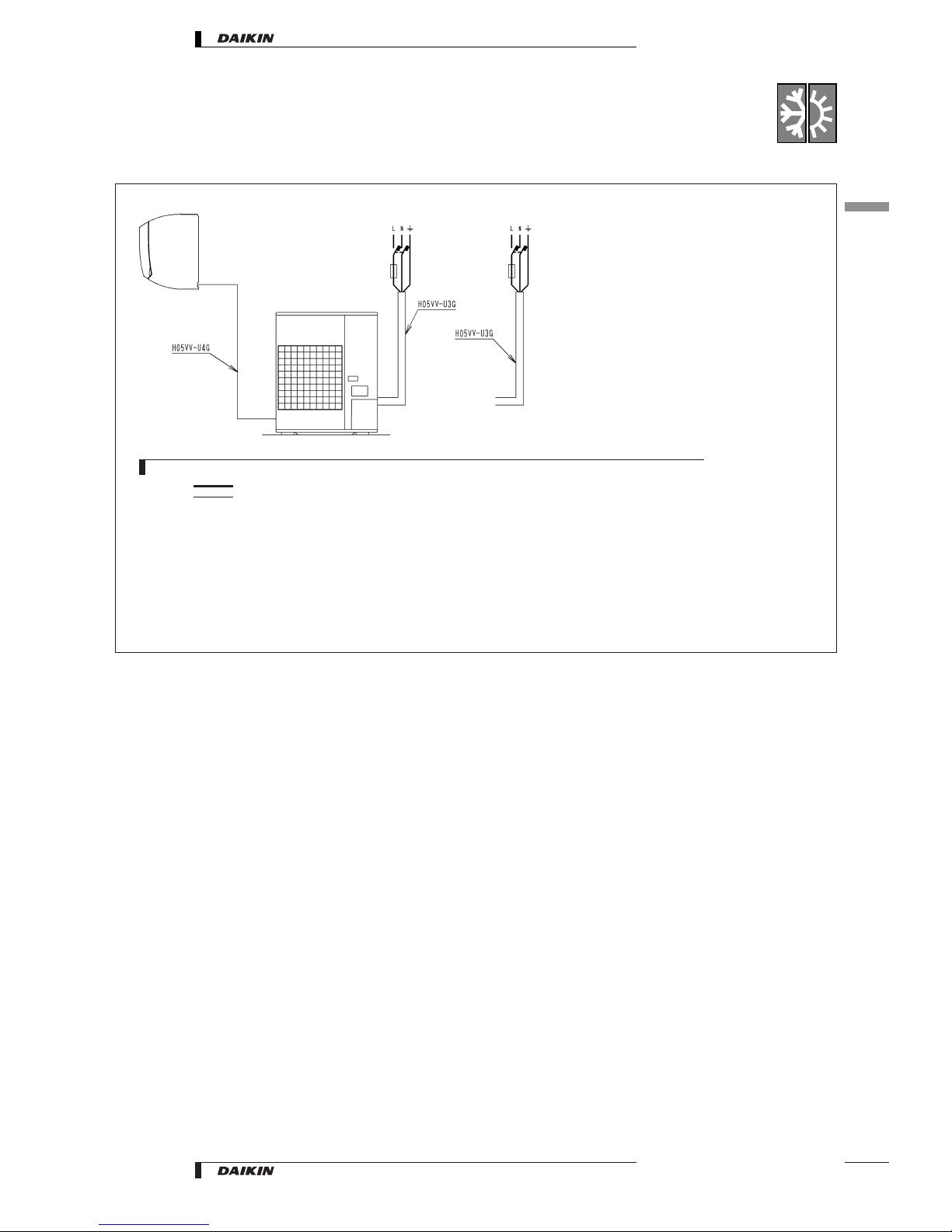
4D044475
V1, Model
Power supply
1∼50Hz
220V-240V
Main switch
Fuse
Fuse
NOTES
1 Line voltage wiring
Control circuit wiring
2 All wiring, components and materials to be produced on the site must comply with the applicable local and national codes.
3 Use copper conductors only.
4 See wiring diagrams for details.
5 Install fuse and mainswitch for safety.
6 All field wiring and components must be provided by a licensed electrician.
7 The unit shall be grounded in compilance with the applicable local and national codes.
8 Wiring shown are general points-of-connection guides only and are not intended for or to include all details for a specific
installation.
9 Never share a common power supply with other equipment.
V3, Model
Power supply
1∼50Hz
230V
Main switch
•
Wall Mounted, Inverter Controlled Unit • R-410A • FAQ71-100BUV1B
5
Wiring diagrams
1
5
9
• Split - Sky Air • Indoor Units
Page 12
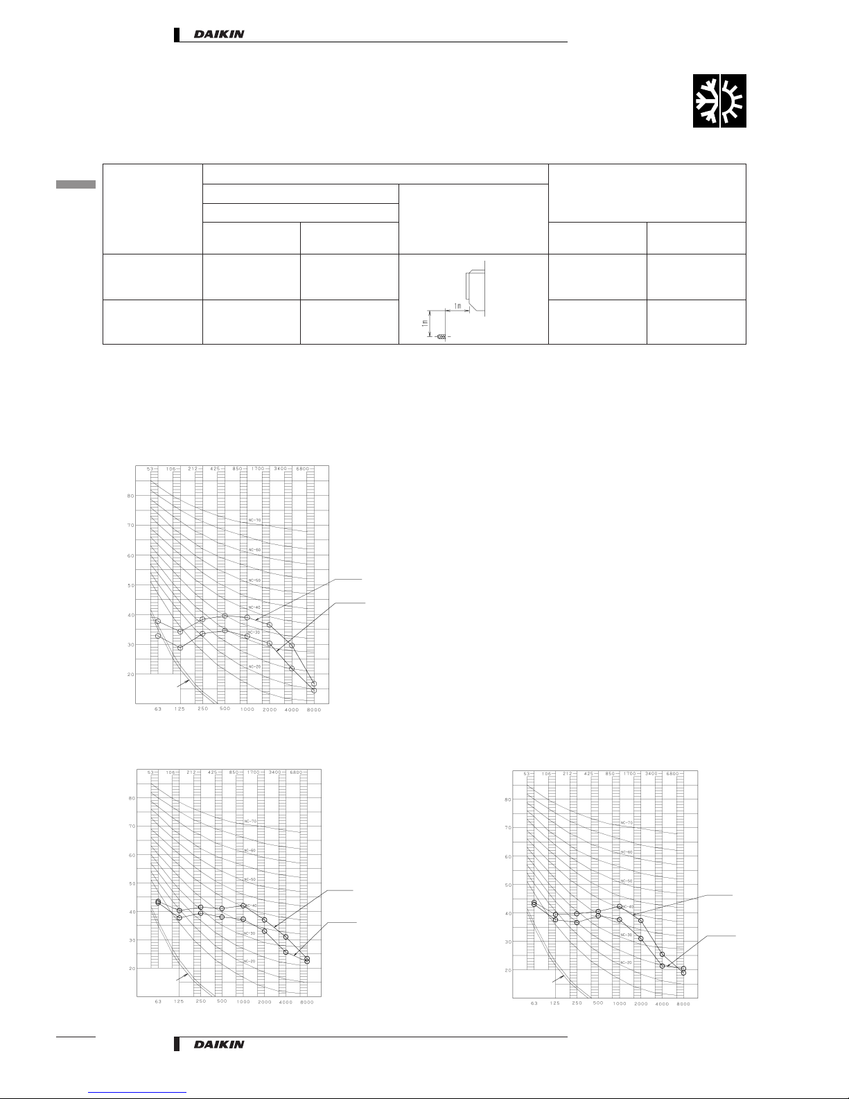
6
Sound levels
6-1
Sound level data
Octave band sound pressure level
Model
Sound pressure level
Sound power level230V
Measuring location
50Hz
Cooling
H/L
Heating
H/L
Cooling
H/L
Heating
H/L
FAQ71BUV1B 43/37 43/37 45/41 45/41
FAQ100BUV1B 59/53 59/53 61/57 61/57
Octave band center frequency (Hz)
FAQ71BUV1B (Cooling/Heating)
4D038512B
6-2
Sound pressure spectrum
approximate
threshold hearing
for continuous
noise
FAQ100BUV1B (Cooling) FAQ100BUV1B (Heating)
Octave band sound pressure level
Octave band sound pressure level
4D027787A 4D027790A
Octave band center frequency (Hz) Octave band center frequency (Hz)
approximate
threshold hearing
for continuous
noise
approximate
threshold hearing
for continuous
noise
Microphone
H (230V)
L (230V)
H (230V)
L (230V)
H (230V)
L (230V)
Note:
1. Sound pressure levels are measured in an anechoic room.
2. Data are valid at nominal operation conditions.
3. Operation sound level differs with operation and ambient conditions.
•
Wall Mounted, Inverter Controlled Unit • R-410A • FAQ71-100BUV1B
1
6
6-1
10
• Split - Sky Air • Indoor Units
Page 13
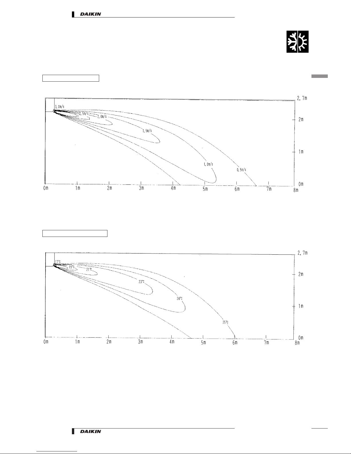
7
Air flow patterns
FAQ71BUV1B
Cooling - air velocity distribution
Air flow direction: 10° (downward)
FAQ71BUV1B
Cooling - air temperature distribution
Air flow direction: 10° (downward)
4D039573A
•
Wall Mounted, Inverter Controlled Unit • R-410A • FAQ71-100BUV1B
1
7
11
• Split - Sky Air • Indoor Units
Page 14
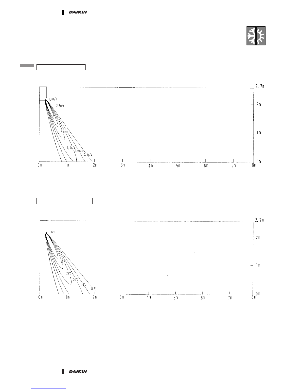
FAQ71BUV1B
Heating - air velocity distribution
Air flow direction: 65°C (downward)
FAQ71BUV1B
Heating - air temperature distribution
Air flow direction: 65°C (downward)
4D039574A
•
Wall Mounted, Inverter Controlled Unit • R-410A • FAQ71-100BUV1B
7
Air flow patterns
1
7
12
• Split - Sky Air • Indoor Units
Page 15
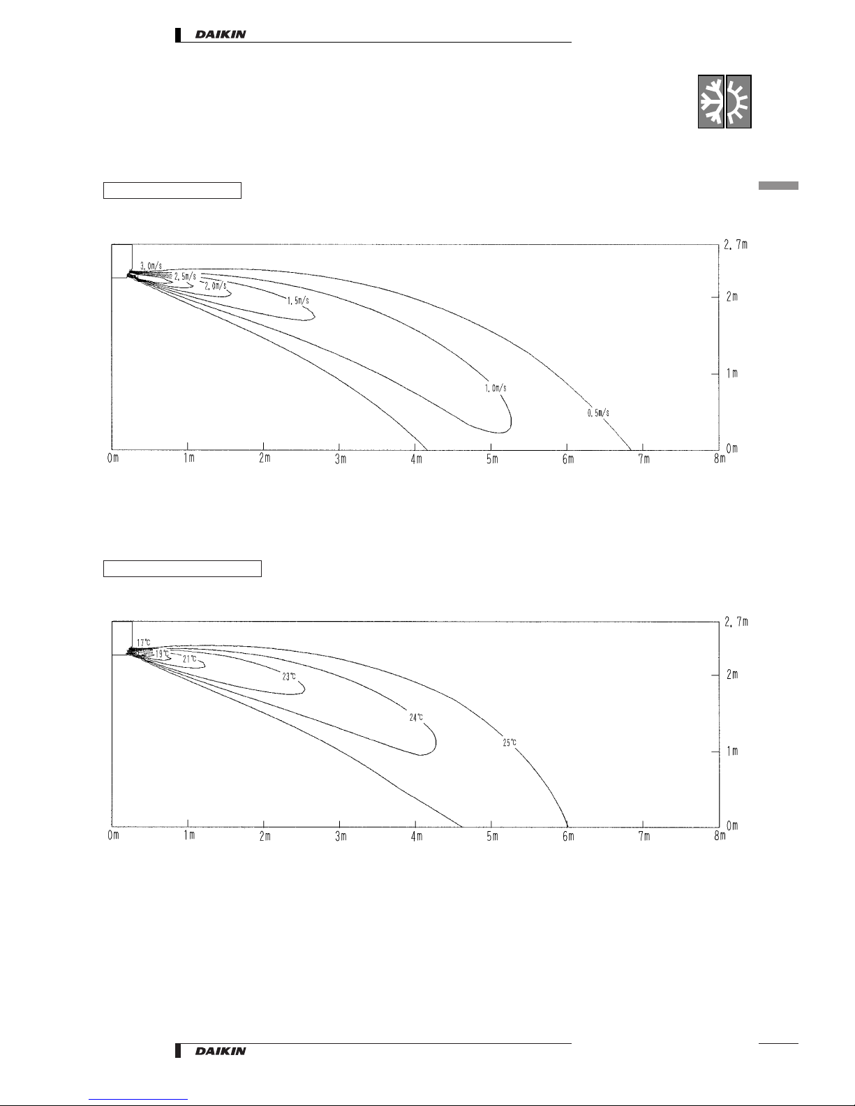
FAQ100BUV1B
Cooling - air velocity distribution
Air flow direction: 10° (downward)
FAQ100BUV1B
Cooling - air temperature distribution
Air flow direction: 10° (downward)
4D028547A
•
Wall Mounted, Inverter Controlled Unit • R-410A • FAQ71-100BUV1B
7
Air flow patterns
1
7
13
• Split - Sky Air • Indoor Units
Page 16
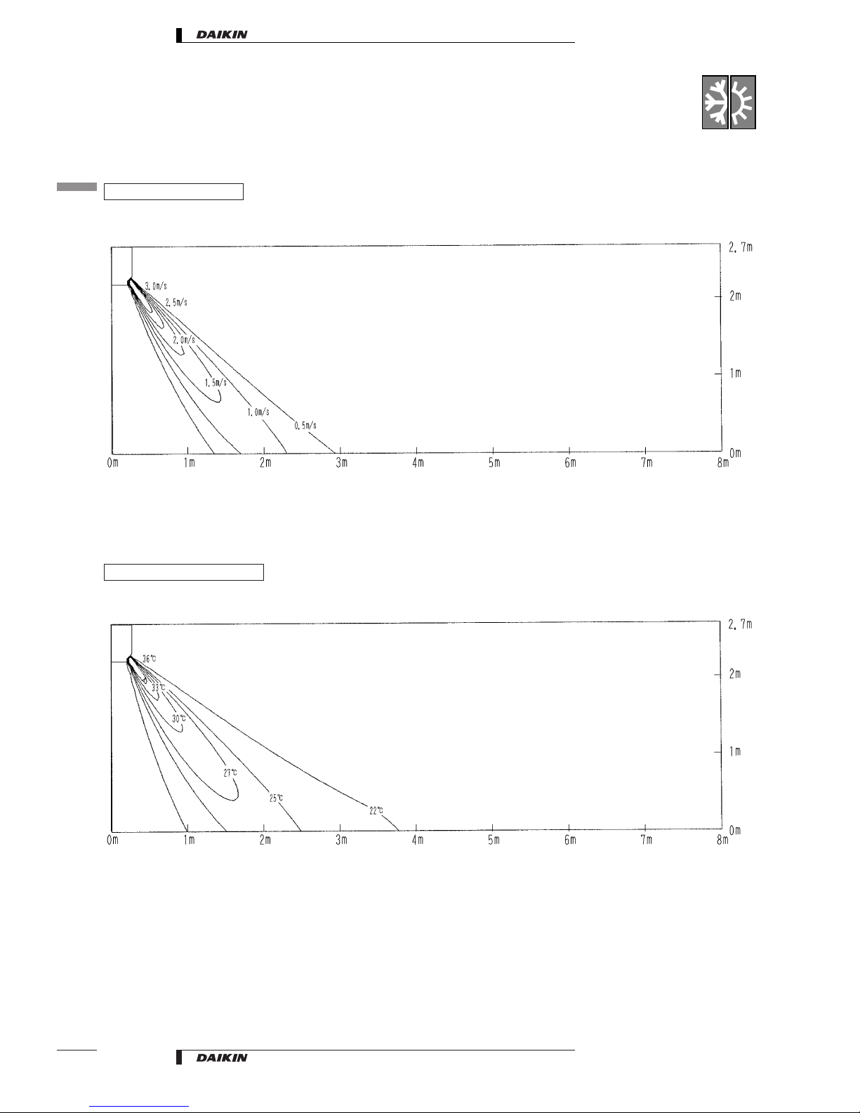
FAQ100BUV1B
Heating - air velocity distribution
Air flow direction: 65°C (downward)
FAQ100BUV1B
Heating - air temperature distribution
Air flow direction: 65°C (downward)
4D028548A
•
Wall Mounted, Inverter Controlled Unit • R-410A • FAQ71-100BUV1B
7
Air flow patterns
1
7
14
• Split - Sky Air • Indoor Units
Page 17
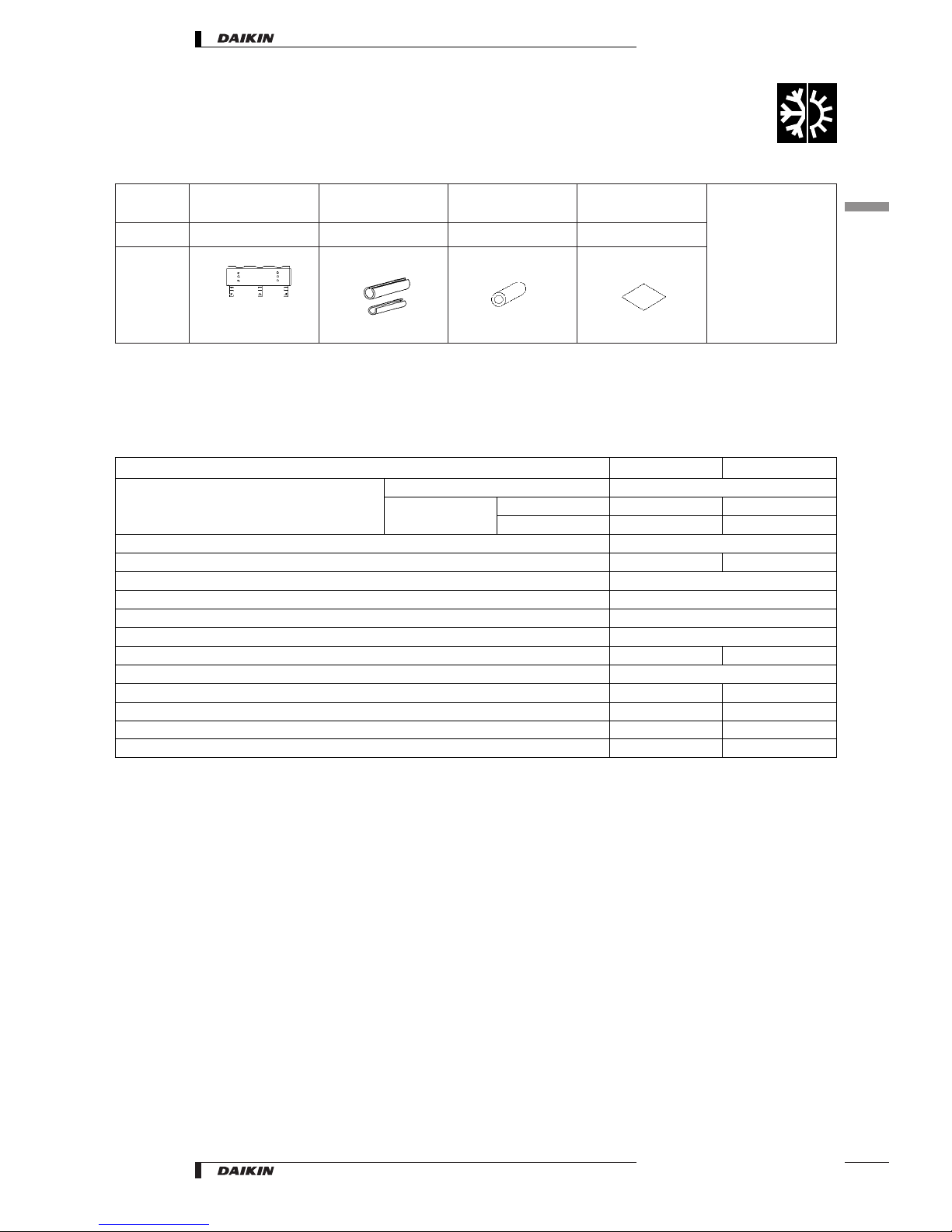
8
Accessories
8-1
Standard accessories
Name 1. Installation panel
Insulation for fitting
(for refrigerant pipe)
4. Insulation tape 5. Paper pattern for installation
(Other)
+ Installation manual
+ Operation manual
Quantity 1 pc. 1 of each 2 pcs. 1 pc.
Shape
6. Screw x 12
2. For liquid pipe
3. For gas pipe
8-2
Optional accessories
Optional accessories FAQ71BUV1B FAQ100BUV1B
Remote control Wired BRC1D527
Infrared type Heat pump BRC7E618 BRC7C510W
Cooling only BRC7E619 BRC7C511W
Wiring adapter for electrical appendices (2)* *KRP4A51
Installation box for adapter PCB KRP4A93 Central remote control DCS302C51
Electrical box with earth terminal (3 blocks) KJB311A
Unified ON/OFF control DCS301B51
Electrical box with earth terminal (2 blocks) KJB212A
Noise filter (for electromagnetic interface use only) KEK26-1 Schedule timer DST301B51
Interface adapter for Sky Air series - DTA112B51
Remote sensor KRCS01-1 Drain up kit K-KDU572CVE Connector for forced on, forced off - EKRORO
3D044482
Note:
1. Installation box (KRP4A93) is necessary for each adapter marked*
•
Wall Mounted, Inverter Controlled Unit • R-410A • FAQ71-100BUV1B
1
8
8-1
15
• Split - Sky Air • Indoor Units
Page 18
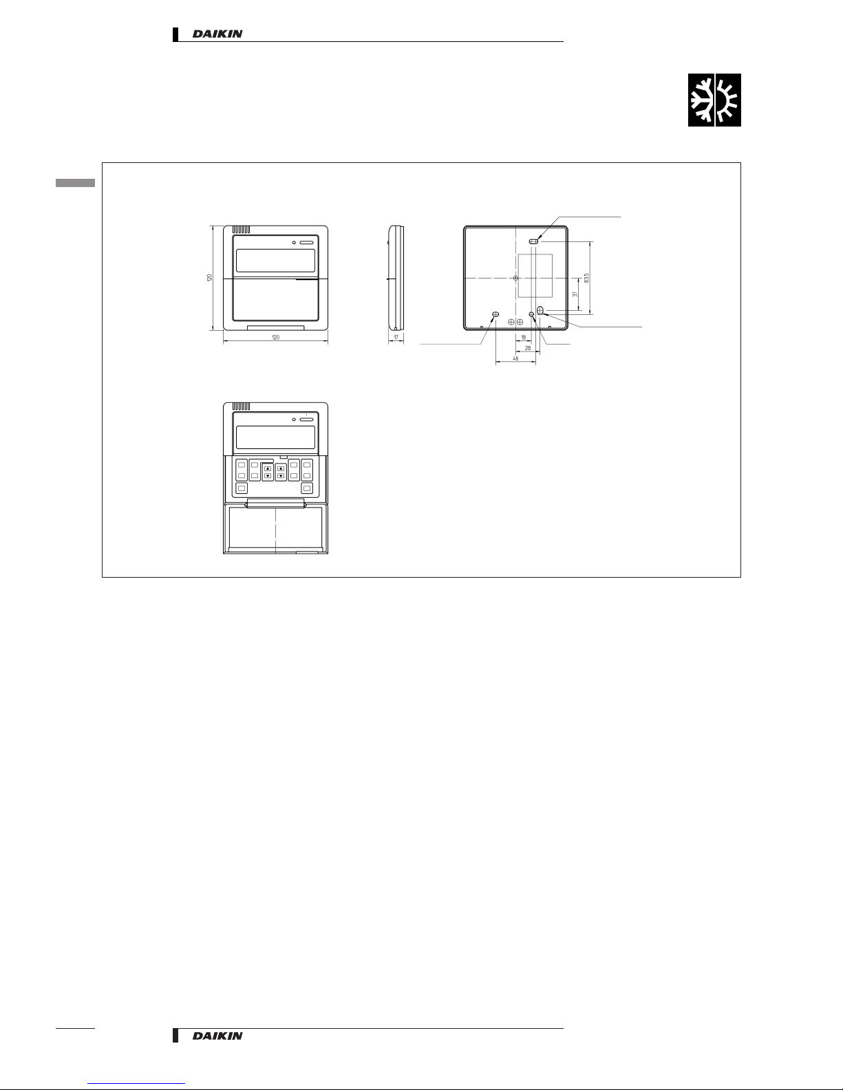
9
Control systems
9-1
Wired remote control
6.5 x 9 (Round end slit)
Cover open
Cover closed
5 x 7 (Round end slit)
HoleJ5
5 x 10 (Round end slit)
3TW23651-2
BRC1D527
•
Wall Mounted, Inverter Controlled Unit • R-410A • FAQ71-100BUV1B
1
9
9-1
16
• Split - Sky Air • Indoor Units
Page 19
10
Safety device settings
FAQ71-100BUV1B
Model Safety devices FAQ71BUV1B FAQ100BUV1B
FAQ∼BUV1B
Fuse −−
Fan motor thermal fuse (°C) −−
Fan motor thermal protector (°C) −
OFF: 130±5
ON: 83±20
DU423-9101K
11
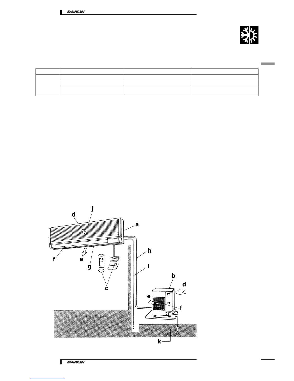
Installation
Names and functions of parts
j
a
Indoor unit
j
b
Outdoor unit
j
c
Infrared remote control
j
d
Inlet air
j
e
Discharged air
j
f
Air outlet
j
g
Air flow flap (at air outlet)
j
h
Refrigerant piping, connection electric wire
j
i
Drain pipe
j
j
Air inlet
The built-in air filter removes dust and dirt.
j
k
Ground wire
Wire to ground from the outdoor unit to prevent electrical shocks.
•
Wall Mounted, Inverter Controlled Unit • R-410A • FAQ71-100BUV1B
1
10
17
• Split - Sky Air • Indoor Units
 Loading...