

Page 1

INSTALLATION MANUAL
Domestic hot water tank for air to
water heat pump system
EKHTS260AC6W1
Page 2
1
2
4
1
2
5 454
66
+
6
33
+
1
2 3
1x 1x
+
+
340 mm
1x
+
+
+
B
++
A
C
++
1x
1x
12 534
>250
>250
>6
00
>1200
6
6
7
2
1
3
5
1
2
4
772
902
1032
2285
120
Ø60
778
2437
2230
694
443
600
300
A
1
2
3
4
Page 3
EKHTS260AC6W1
Domestic hot water tank
for air to water heat pump system
Installation manual
CONTENTS Page
Introduction........................................................................................ 1
General information.....................................................................1
Scope of this manual...................................................................1
Model identification .....................................................................1
Accessories .......................................................................................1
Accessories supplied with the domestic hot water tank .............1
Optional equipment..................................................................... 1
Overview of the unit........................................................................... 2
Position of flexibles...................................................................... 2
Main components........................................................................2
Safety devices.............................................................................3
Outlook diagram..........................................................................3
Installation of the EKHTS domestic hot water tank ...........................3
Installation guidelines..................................................................3
Installing and commissioning the domestic hot water tank .........4
Maintenance...................................................................................... 7
Descaling ....................................................................................7
Draining.......................................................................................8
Troubleshooting .................................................................................8
General guidelines ......................................................................8
General symptoms ...................................................................... 8
Disposal requirements....................................................................... 8
Technical specifications.....................................................................8
Domestic hot water tank specifications ....................................... 8
READ THESE INSTRUCTIONS CAREFULLY BEFORE
INSTALLATION. KEEP THIS MANUAL IN A HANDY
PLACE FOR FUTURE REFERENCE.
PLEASE LEAVE THIS MANUAL WITH THE EKHTS
DOMESTIC HOT WATER TANK AFTER INSTALLATION.
IMPROPER INSTALLATION OR ATTACHMENT OF
EQUIPMENT OR ACCESSORIES COULD RESULT IN
ELECTRIC SHOCK, SHORT-CIRCUIT, LEAKS, FIRE OR
OTHER DAMAGE TO THE EQUIPMENT. BE SURE ONLY
TO USE ACCESSORIES MADE BY DAIKIN WHICH ARE
SPECIFICALLY DESIGNED FOR USE WITH THE
EQUIPMENT AND HAVE THEM INSTALLED BY A
PROFESSIONAL.
IF UNSURE OF INSTALLATION PROCEDURES OR USE,
ALWAYS CONTACT YOUR DAIKIN DEALER FOR
ADVICE AND INFORMATION.
THE UNIT DESCRIBED IN THIS MANUAL IS DESIGNED
FOR INDOOR INSTALLATION ONLY AND FOR AMBIENT
TEMPERATURES RANGING 5°C~30°C.
INTRODUCTION
General information
Thank you for purchasing this domestic hot water tank.
The domestic hot water tank must be installed by a licensed
technician and be installed in compliance with instructions as of
subject in this manual, all current legislation, codes of practice and
regulations governing the installation of unvented hot water cylinders
in force at the date of installation.
The EKHTS domestic hot water tank can be connected to EKHBRD*
units. The domestic hot water tank is available in one size:
approximately 260 litre. The domestic hot water tank can be mounted
on top of the indoor unit. For installation of the domestic hot water
tank on the floor next to the indoor unit, the dedicated EKFMAHTB
connection kit is required.
In case of EKHBRD*AA* units, the kit EKMKHT1 is required.
Scope of this manual
This installation manual describes the procedures for installing and
connecting the EKHTS domestic hot water tank.
Model identification
Domestic hot water tank
EK HTS 260 AC 6 W1
Power supply (3~, 400 V, 50 Hz)
Power of heater
Series
Identification of type
Hot water Tank Stainless steel
European Kit
ACCESSORIES
Accessories supplied with the domestic hot water tank
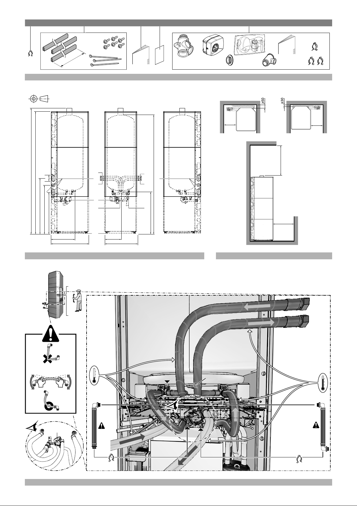
See figure 1.
1 Clamp
2 Knock-out hole assembly (grommet + tie-wraps + screws)
3 Installation manual
4 Unpacking instruction sheet
5 3-way valve assembly (body + motor + clamps) + T-piece
The English text is the original instruction. Other languages are
translations of the original instructions.
EKHTS260AC6W1
Domestic hot water tank for air to water heat pump system
4PW73828-1 – 2012.05
Optional equipment
■ EKFMAHTB
Connection kit for installation of the domestic hot water tank on
the floor next to the indoor unit.
Refer to the installation manual of the kit for more details.
■ EKMKHT1
In case the EKHTS*AC domestic hot water tank is to be installed
on top of an EKHBRD*AA* series indoor unit, the additional
EKMKHT1 kit is required.
Refer to the instruction sheet of the kit for more details.
Installation manual
1
Page 4
OVERVIEW OF THE UNIT
A
K
G
J
F
E
M
N
G
C
D
J
L
B
A
K
P
H
E
The total system (indoor unit and outdoor unit) is designed
for combination with a Daikin domestic hot water tank. In
case another tank is being used in combination with the
Daikin indoor unit, Daikin cannot guarantee neither good
operation nor reliability of the system. For those reasons
Daikin cannot give warranty of the system in such case.
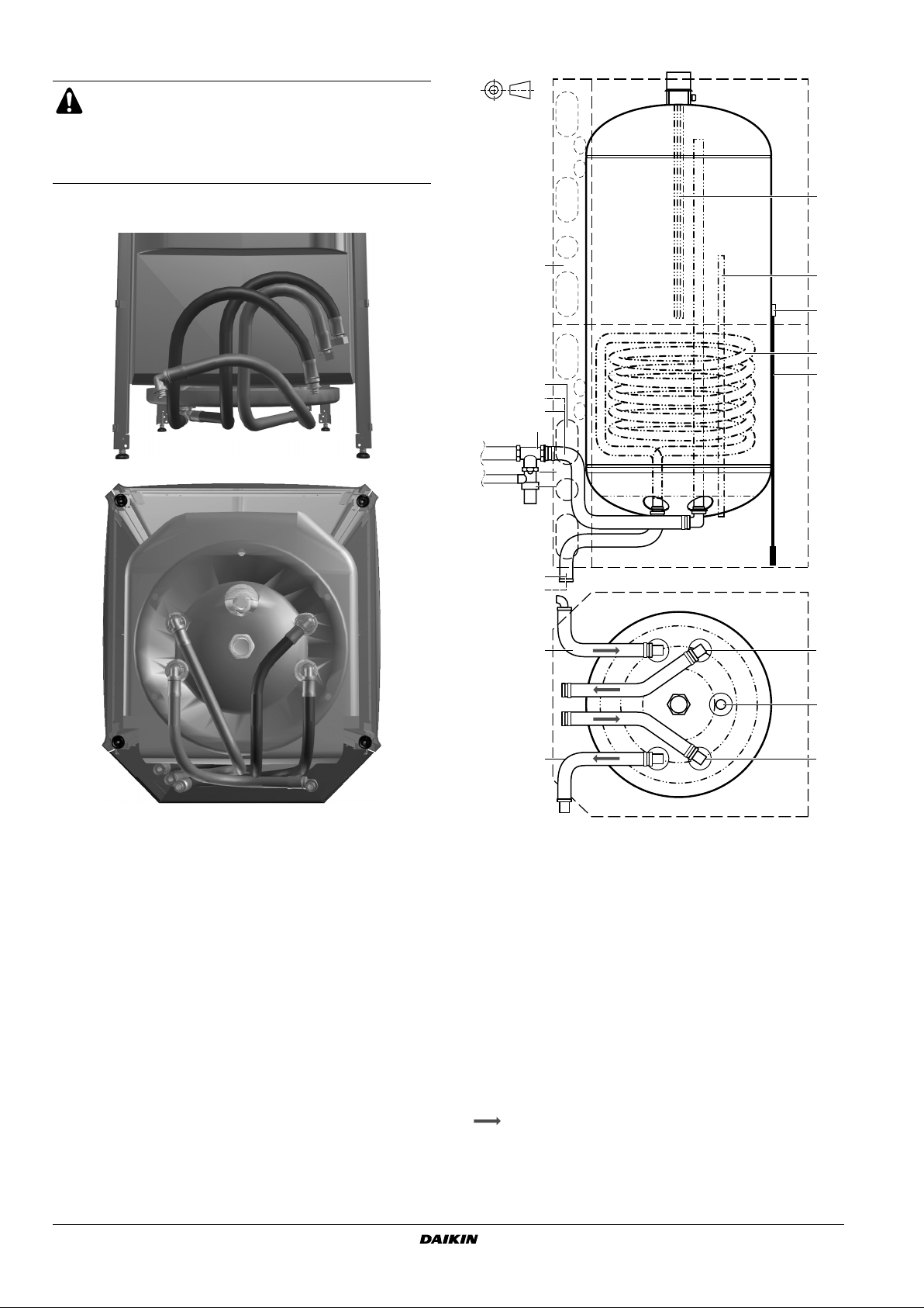
Position of flexibles (Factory mounted)
Main components
A Hot water from the tank (G 3/4" Female)
B T-piece (field supply)
C Pressure relief valve connection (field supply)
D Pressure relief valve (field supply)
E Anode
F Thermistor socket
G Hot water from the indoor unit to the tank coil (quick coupling 90°)
H Heat exchanger coil
J Return water from the tank coil to the indoor unit (quick coupling)
K Cold water to the tank (G 3/4" Female)
L Thermistor
M electric heater
N Casing
P Knock-out holes for water piping
Water flow direction
Installation manual
2
Domestic hot water tank for air to water heat pump system
EKHTS260AC6W1
4PW73828-1 – 2012.05
Page 5

Safety devices
■ The domestic hot water tank relief valve connections
may not be used for other purpose.
■ This domestic hot water tank can only be used with an
EKHBRD* unit.
■ Thermal protector — The heat pump unit is equipped with a
thermal protector. The thermal protector is activated when the
temperature becomes too high. When activated, the protector
has to be reset on the heat pump unit by pressing it (for access,
remove the decoration panels like indicated in the manual of the
heat pump unit).
Switch off the power supply before opening the
decoration panels of the indoor unit.
■ Thermal protector electric heater — The electric heater is
equipped with a thermal protector. The thermal protector is
activated when the temperature becomes too high. When
activated, the protector has to be reset on the electric heater by
pressing it (for access, remove the cover of the electric heater).
Switch off the power supply before opening the cover
of the electric heater.
■ Pressure relief valve — A pressure relief valve (field supply) in
accordance with relevant local and national regulations, and with
an opening pressure of maximum 10 bar must be connected to
the pressure relief valve connection.
■ If a discharge pipe is connected to the pressure relief device it
must be installed in a continuously downward direction and in a
frost-free environment. It must be left open to the atmosphere.
Outlook diagram (See figure 2 and figure 3)
1 Hot water from the tank (G 3/4" Female)
2 Cold water to the tank (G 3/4" Female)
3 Hot water from the indoor unit to the tank coil (quick coupling 90°)
4 Return water from the tank coil to the indoor unit (quick coupling)
5 3-way valve
6 Knock-out holes for water piping
7 Levelling feet
A Adviced service height above the tank to allow the replacement of
the electric heater element without having to empty and turning
the tank.
INSTALLATION OF THE EKHTS DOMESTIC HOT
WATER TANK
■ Installation shall be done by a licensed technician, the
choice of materials and installation shall comply with
local and national regulations.
■ The equipment is not intended for use in a potentially
explosive atmosphere.
■ Domestic hot water quality must be according to EU
directive 98/83 EC.
■ A drain device should be installed on the cold water
connection on the domestic hot water tank.
■ For safety reasons, it is not allowed to add any kind of
glycol to the water circuit.
■ To avoid stagnation of water, it is important that the
storage capacity of the domestic hot water tank meets
the daily consumption of domestic hot water.
In cases where during longer periods of time there is
no consumption of hot water, the equipment must be
flushed with fresh water before usage.
The disinfection function provided on the equipment is
specified in the operation manual of the indoor unit.
■ It is advised to avoid long runs of piping between the
domestic hot water tank and the hot water end point
(shower, bath, ...) and to avoid dead ends.
■ The installation must be in compliance with local and
national regulations and may require additional
hygienic installation measures.
■ In accordance with local and national regulations it
may be necessary to install thermostatic mixing
valves.
■ Immediately after installation, the domestic hot water
tank must be flushed with fresh water. This procedure
must be repeated at least once a day the first
5 consecutive days after installation.
If required by relevant local and national regulations, connect a
recirculation pump in between the hot water end point and the cold
water connection of the domestic hot water tank.
1 Cold water connection
2 Hot water connection
3 Shower
4 Recirculation pump
1 2
3
4
EKHTS260AC6W1
Domestic hot water tank for air to water heat pump system
4PW73828-1 – 2012.05
Installation guidelines
Keep in mind the following guidelines when installing the domestic
hot water tank:
■ The installation location is frost-free.
■ Standard installation location of the domestic hot water tank is
on top of the indoor unit.
If available service space to left and/or right side is
limited, carefully consider all indoor module
installation steps first.
■ The domestic hot water tank can be floor mounted as well. In
that case, the dedicated EKFMAHTB connection kit for
installation of the domestic hot water tank next to the indoor unit
is required and to be ordered separately.
■ Locate the domestic hot water tank in a suitable position to
facilitate ease of maintenance. Refer to the grey-coloured zones
indicated in the outlook diagram figure and to the installation
manual of the indoor unit.
Installation manual
3
Page 6

■ To avoid back siphonage it is advised to install a non-return
2x2x
2x
3
1
1
1
2x
45
45
valve on the water inlet of the domestic hot water tank in
accordance with local and national regulations.
■ Ta ke care that in the event of a leak, water can not cause any
damage to the installation space and surroundings.
■ Provide a connection for the pressure relief valve and drain on
the cold water inlet.
■ It is advised to install a pressure reducing valve on the cold
water inlet in accordance with local and national regulations.
■ An expansion vessel should be installed on the cold water inlet
in accordance with local and national regulations.
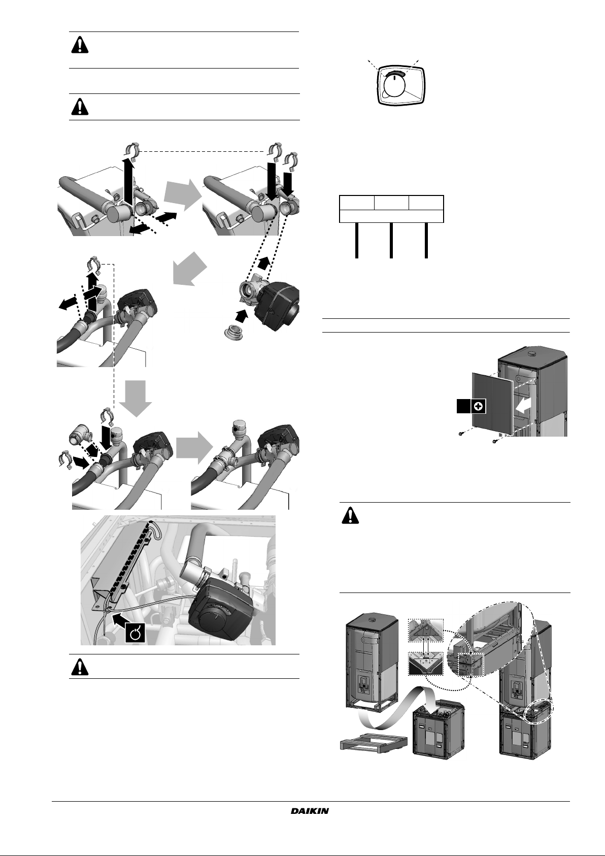
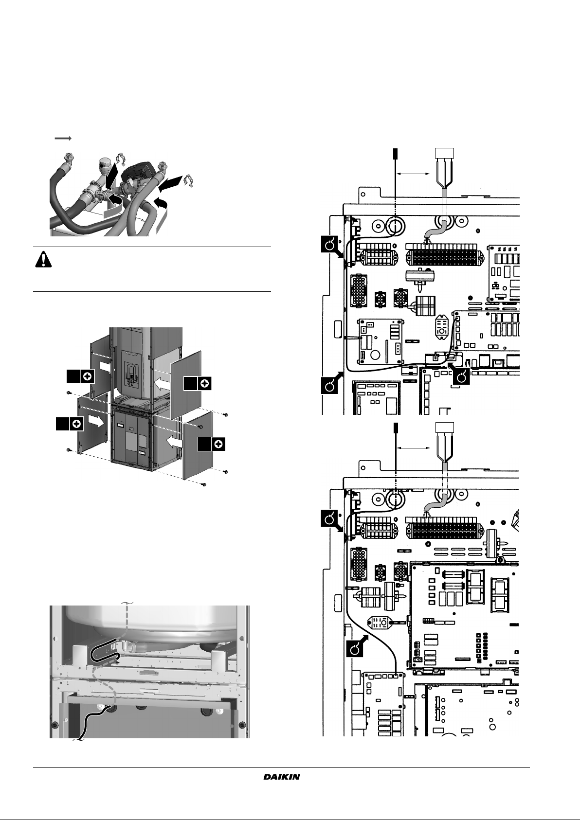
Remove the indoor unit switch box by unscrewing fixations and
by then sliding the switch box aside without disconnecting any
wiring connections.
4x
Installing and commissioning the domestic hot water
tank
■ Unpack the domestic hot water tank according to the
instructions mentioned on the unpacking instruction sheet.
■ Check if all domestic hot water tank accessories are enclosed
(see "Accessories" on page 1).
Remove the indoor unit casing.
Ta ke away the decoration panels by removing the 2 bottom screws
and then unhitching the panel. Remove the top panel.
Connect the 3-way valve to the indoor unit
Refer to the instruction sheet delivered with the 3-way
valve.
MAX.
15 cm
2 Installation position.
This 3-way valve must be installed in the indoor unit.
1
1 From unit
2 To domestic hot water tank
3 To room heating
2
3
3 Unpack the 3-way valve body and 3-way valve motor.
Ver ify that following accessories are provided with the motor.
2
1
1 Sleeve 3 Screw
2 Valve motor cover 4 Tu rn knob
3 4
4 Put the sleeve on the valve and turn the valve so that the sleeve
is positioned according to the figure below.
1 Remove both parts of the drain plate
on top of the indoor unit before
installing the 3-way valve.
Installation manual
4
4x4x
°45°
45
°45°
45
45°
Domestic hot water tank for air to water heat pump system
EKHTS260AC6W1
4PW73828-1 – 2012.05
Page 7
If the valve is not positioned in this way before mount-
B
C
1
2
2
3
4
5
10
11
9
7
8
8
6
2x
ing the motor, the valve will give way to both domestic
water and room heating during operation.
5 Install the 3-way valve body in the pipework.
Avoid contact between hot piping and electrical wiring
at all time.
Refer to the figure below before making the connection.
7 Put the turn knob on the valve motor cover as shown below.
Room heating Domestic hot water tank
Make sure that the turn knob is completely pushed in to allow
the turn knob being operated automatically by the unit. If the turn
knob is lifted slightly, manual operation is possible.
8 Perform the wiring in the (indoor) unit switch box in accordance
with the following figure: (make sure power supply is switched off)
X2M
345
3-way valve
BLU
BLK
BRN
NYL
Make sure to follow the appropriate wiring routing inside of the
unit (this wiring routing can be found in the installation manual of
the indoor unit).
Refer also to the wiring diagram delivered with the indoor unit.
Installing the hot water tank on top of the indoor unit
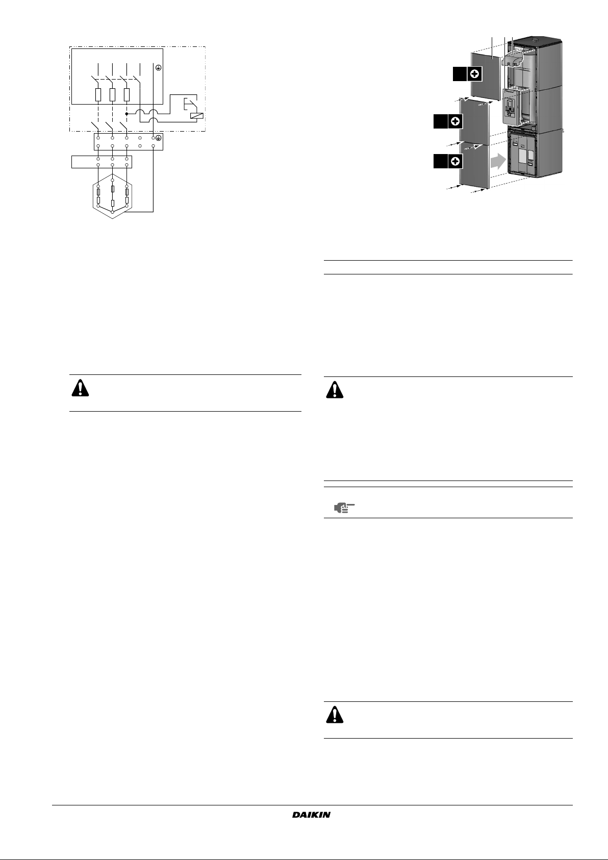
1 Remove the top front
decoration panel of the tank
module as indicated in the
figure.
2 Routing of the flexible hoses
with threaded connection
coupling (G 3/4” female).
Depending on the installation
location (left or right side
installation), punch the
required right or left knock-out
holes out of the rear plate. Apply the grommet to the edges of
the knocked out holes to protect the flexible hoses.
3 Mount the tank module on top of the indoor unit.
■ Because of the weight of the domestic hot water
tank, it is advised to handle and lift it with two
persons.
■ Refer to the figure below and make sure that the
positioning guides on all four corners of the
domestic hot water tank bottom perfectly match
on the positioning guides of the indoor unit top
when mounting the tank module.
12
The 3-way valve needs to be installed indoors.
6 Push the motor on the sleeve.
Make sure not to rotate the sleeve during this action, so as to
maintain the valve position as set during step 4.
EKHTS260AC6W1
Domestic hot water tank for air to water heat pump system
4PW73828-1 – 2012.05
Installation manual
5
Page 8
4 Connect the flexible hoses as indicated below and in figure 4.
2x
2x
2x
2x
2
2
1
1
1
1
2
2
3
3
3
3
X11A
A3P
BLU
BLK
BRN
NYL
3-way
valve
X2M
3 4 5
>25 mm
1~
1 Hot water from the tank (G 3/4" Female)
2 Cold water to the tank (G 3/4" Female)
3 Anode
4 Hot water from the indoor unit to the tank coil (quick coupling
90°)
5 Return water from the tank coil to the indoor unit
(quick coupling)
6 3-way valve
Water flow direction
The distance between the thermistor cable and power supply
cable must always be at least 25 mm to prevent electromagnetic
interference on the thermistor cable.
1 Plug the thermistor cable connector in the socket X11A
(A3P) on the PCB.
2 Fix the cables to the cable tie mountings with cable ties to
ensure strain relief.
3 When routing out cables, make sure that these do not
obstruct mounting of the indoor unit cover.
Note: only relevant field wiring is shown.
2
1
4
3
It is recommended to install a shut off valve to the cold
water inlet. Close this shut off valve during periods of
absence to avoid damage to the surroundings in case
water should leak.
5 Fix the side bottom decoration panels of the domestic hot water
tank to the indoor unit.
3~
>25 mm
3-way
valve
NYL
BLU
BLK
BRN
1 Decoration panel
2 Quick fixation hole
3 Fasten with 2 screws
6 Connect the pressure relief valve (field supply, opening pressure
maximum 10 bar) and the drain.
7 Connect the thermistor wire to the indoor unit switch box. Make
sure power supply is switched off. Refer to the wiring diagram
delivered with the indoor unit.
Installation manual
6
X2M
3 4 5
X11A
A3P
Domestic hot water tank for air to water heat pump system
EKHTS260AC6W1
4PW73828-1 – 2012.05
Page 9
8 Connection of electric heater
3~ 400 V 50 Hz
L1
DI
Q
*
F1
KIM
L1L2L2L3L3NN
T
C/TCO
TF
R
Q*DI Earth leakage protector (field supply)
F1 Fuse (field supply)
SI Emergency switch (field supply)
KIM Contactor (field supply)
Tc Thermostat (78°C)
Tco Thermal cut out (92~99°C)
TF Thermal fuse
R Resistor
SI
KIM
11
Reattach the front
decoration panels of
123
the domestic hot water
tank.
2x
2x
12 Reattach the front
decoration panel of
2x
the indoor unit.
1 Decoration panel
2 Insulation piece
3 Temperature and pressure
relief valve insulation piece
Installing the hot water tank by the side of the indoor unit
Refer to the manual delivered with the kit EKFMAHTB.
MAINTENANCE
9 Reattach the drain plate on the indoor unit.
10 Commissioning
The domestic hot water tank coil must be filled with
water at the indoor unit water inlet. This to avoid that
dirt enters the system.
Follow the next steps to fill up the tank:
1 Open each hot water tap in turn to expel air from the system
pipe work.
2 Open the cold water supply valve. Make sure the decoration
panels of both the domestic hot water tank and the indoor
unit are aligned.
3 Close all water taps after all air is expelled.
4 Check for leaks.
5 Manually operate the temperature and pressure relief valve
to ensure free water flow through the discharge pipe (turn
knob counterclockwise). Refer to "Main components" on
page 2 for location of the temperature and pressure relief
valve.
In order to ensure optimal availability of the unit, a number of checks
and inspections on the unit and the field wiring have to be carried out
at regular intervals.
■ Each inspection has to be carried out by a licensed
technician and not by the user.
■ Before carrying out any maintenance or repair activity,
always switch off the circuit breaker on the supply
panel, remove the fuses or open the protection
devices of the unit.
■ Make sure that before starting any maintenance or
repair activity, also the power supply to the outdoor
unit is switched off.
NOTE
The flexible hoses are designed for a 13 year lifetime.
It is adviced to replace them after this period.
The described checks must be executed at least once a year by a
licensed technician.
1 Domestic hot water tank pressure relief valve (field supply)
Check for correct operation of the pressure relief valve on the
domestic hot water tank.
2 Remove the bottom front panel of the water tank to check for
water leaks (first remove the front panel of the indoor unit when
the water tank is mounted on top of the unit).
EKHTS260AC6W1
Domestic hot water tank for air to water heat pump system
4PW73828-1 – 2012.05
Descaling
Depending on the water quality and set temperature, scale can
deposit on the heat exchanger inside the domestic hot water tank
and can restrict heat transfer. For this reason, descaling of the heat
exchanger may be required at certain intervals.
When using means for descaling, it must be ensured that
the water quality remains compliant with the requirements
of EU directive 98/83/EC.
Installation manual
7
Page 10

Draining
Follow the next steps to drain the tank:
1 Switch off the power supply.
2 Tu rn off the cold water supply valve.
3 Open the hot water taps.
4 Open the drain valve.
TROUBLESHOOTING
This section provides useful information for diagnosing and
correcting certain troubles which may occur in the unit.
General guidelines
Before starting the trouble shooting procedure, carry out a thorough
visual inspection of the unit and look for obvious defects such as
loose connections or defective wiring.
When carrying out an inspection on the supply panel or on
the switch box of the unit, always make sure that the circuit
breaker of the unit is switched off.
When a safety device was activated, stop the unit and find out why
the safety device was activated before resetting it. Under no circumstances safety devices may be bridged or changed to a value other
than the factory setting. If the cause of the problem cannot be found,
call your local dealer.
Symptom 4: Dirty water
POSSIBLE CAUSES CORRECTIVE ACTION
Dirty water Flush or clean the domestic hot
water tank after periods of standstill.
It could occur that particles in the
water deposit on the bottom of the
tank. If this deposit layer becomes
thick enough it could enter the hot
water outlet and contaminate the hot
water.
The water has a smell of rotten eggs. Check if this phenomena also occurs
with the cold water. If it does, this
indicates that there is a problem with
the water supply or with the water in
the piping, but not with the domestic
hot water tank itself.
Contact your water supplier.
If the problem is not solved, increase
the domestic hot water tank
temperature above 65°C.
If this action solves the problem, the
smell is most probably caused by
bacterial contamination. Contact
your water supplier.
If the problem is not solved, contact
your local dealer.
Symptom 5: electric heater is not operating
POSSIBLE CAUSES CORRECTIVE ACTION
The thermal cut out operated. Open the cover of the electric heater
and reset the thermal cut out by
pressing the button.
The thermal fuses are blown. Replace the electric heater.
DISPOSAL REQUIREMENTS
General symptoms
Symptom 1: No water flow from hot taps
POSSIBLE CAUSES CORRECTIVE ACTION
The main water supply is off. Check that all shut off valves of the
Symptom 2: Water from hot taps is cold
POSSIBLE CAUSES CORRECTIVE ACTION
The thermal cut-out located in the
indoor unit has operated
The indoor unit is not operating. Check the indoor unit operation.
Symptom 3: Intermittent water discharge
POSSIBLE CAUSES CORRECTIVE ACTION
Thermal control failure (water will be
hot).
water circuit are completely open.
• Check and find the cause of tripping
and then reset button.
• Check if thermistor is correctly
installed in thermistor socket.
Procedure: remove front panel and
insulation, replace or fix the sensor.
Refer to the manual delivered with
the unit.
If any faults are suspected, contact
your local dealer.
Contact your local dealer.
Dismantling of the unit and treatment of parts must be done in
accordance with relevant local and national legislation.
TECHNICAL SPECIFICATIONS
Domestic hot water tank specifications
(mm)
(bar)
(kg)
(kg)
(bar)
(°C)
(°C)
(l)
(l)
260
7.5
1610 x 600 x 695
3
connection
78
330
10
75
85
Storage capacity
Internal heat exchanger volume
Material Stainless steel
Overall dimensions (h x l x w)
Maximum primary working
pressure (heating side)
Connections Quick coupling G 3/4" F
Type of inspection hole G 1/2" Electric heater element
Weight
- empty
- when full
Mounting On top of unit or floor mounted
Maximum water supply pressure
Maximum temperature domestic
hot water
Maximum temperature heat
exchanger
Installation manual
8
Domestic hot water tank for air to water heat pump system
EKHTS260AC6W1
4PW73828-1 – 2012.05
Page 11

Page 12

4PW73828-1 2012.05
Copyright 2012 Daikin
 Loading...